Category Archives: Articles

Dan reviews the new Chameleon CHA RXL Pro Wideband Magnetic Loop Antenna

Many thanks to SWLing Post contributor, Dan Robinson, for the following guest post and review:


Photo by Chameleon

The Chameleon CHA-RXL Pro:  Improved Amp Board Raises the Game

by Dan Robinson

Back in 2021 I reviewed the CHA-RXL loop by Chameleon.  This loop antenna is sold by major retailers such as DX Engineering, Gigaparts and Chameleon itself – the company is a well-known name in antennas and other equipment for the amateur radio world.

I compared the CHA-RXL to Wellbrook 1530 and W6LVP loops feeding into a four-position Delta antenna switcher, and then to a Raven 16 port multicoupler which maintains good steady gain.

My Wellbrook is mounted on a telescopic mast about 15 feet above ground level, with a rotor.  The W6LVP (using LMR400 coax) is tripod-mounted with an overall height from ground of about 12 feet. It has special filters to prevent strong medium wave signals from bleeding into HF.

I have since added a UK-made loop (essentially a copy of a Wellbrook loop but smaller diameter and made of metal) combined with a W6LVP amp.  This W6 amp does not have filtering to block strong mediumwave signals.  In all, I have four loops into my Delta switcher, which feeds about two dozen receivers.

There is by the way quite robust discussion at https://groups.io/g/loopantennas about various loops, including the Chameleon.  And this past July, Steve Ratzlaff posted news about the upgraded loop amp board which will ship with what is now the CHA RXL Pro, saying:

“Chameleon has completely redone their CHA RXL loop amp board from the previous poor-performing loop amp that I tested some time back, and sent me one of the new production boards to test. I’m happy to say it tests very well especially for LF sensitivity, and I can now give it my “seal of approval”.  The new board is a version of the LZ1AQ loop amp.”

Photo by Chameleon

It turns out, according to an email from Don Sherman of Chameleon, that Steve is one of the engineers who helped design the new amp board for the CHA RXL Pro, and on the Loop Antenna group he provides a folder in which he placed previous test results with “new files of the new board (sweep of the new RXL Pro loop amp, and a picture of the new amp PCB).”

Continue reading

Spread the radio love

Small Unidirectional Loop Antenna (SULA) Part 2: Construction Notes

Many thanks to SWLing Post contributor extraordinaire, 13dka, who brings us Part Two of a three part series about the new SULA homebrew antenna project. This first article describes this affordable antenna and demonstrates its unique reception properties. This second article focuses on construction notes. The third and final article will essentially be a Q&A about the SULA antenna. All articles will eventually link to each other once published.

This wideband unidirectional antenna is an outstanding and innovative development for the portable DXer. I love the fact that it came to fruition via a collaboration between Grayhat and 13dka: two amazing gents and radio ambassadors on our SWLing.net discussion board and here on the SWLing Post. So many thanks to both of them!

Please enjoy and share Part 2:


Part 2: SULA Construction notes

by 13dka

The drawing [above] has all you need to know. You basically need to put up a symmetrical wire diamond starting with a balun at the one end and terminating in a resistor at the other end of the horizontal boom, the sides are supposed to be 76cm/29.92″ long so you need to make yourself some…

Support structure:

I used 0.63″/1.6cm square plastic square tubing/cable duct profiles from the home improvement market to make the support structure. You can use anything non-conductive for that of course, broom sticks, lathes… The plastic profiles I used had the advantage of being in the house and easy to work on with a Dremel-style tool and everything can be assembled using the same self-tapping screws without even drilling. The profiles are held together with 2 screws, for transport I unscrew one of them and put that into an extra “parking” screw hole on the side, then I can collapse the cross for easy fit into the trunk, a rucksack etc.

These profiles are available in different diameters that fit into each other like a telescoping whip. This is useful to make the support structure variable for experiments and to control the loop shape and tension on the wire. The booms end up at 1.075m each, the profiles come in 1m length, so that’s 4 short pieces of the smaller size tube to extend the main booms by 37mm on each side

On the resistor end of the loop that smaller tube isn’t mounted in the “boom” tube but to the side of it in order to keep the wire running straight from the balun box on the other side.

Mast/mounting:

You can use anything non-conductive to bring it up to height. On second thought that is indeed bad news if you were planning on putting that up on your metal mast…and we have no data on what happens when you do it anyway. I don’t know if the smallest (4m) telescoping fiberglass poles would suffice for portable operation, but I’m a fan of just using the big lower segments of my 10m “HD” mast for the stiffness they give me (3 segments for the height, the 4th collapsed into in the base segment for easy rotation). Telescoping masts also give you easy control over…

Height:

The published patterns are for 3m/10′ feedpoint height over “average” ground. Increasing height further has no expectable advantage, instead it will deteriorate the favorable directional pattern of the loop. Flying it lower, or even a lot lower in windy weather on the other hand is causing a surprisingly moderate hit on performance.

Continue reading

Spread the radio love

Introducing the amazing SULA: An affordable unidirectional DX-grade loop antenna that you can build!

Many thanks to SWLing Post contributor extraordinaire, 13dka, who brings us a three part series about the new SULA homebrew antenna project. This first article describes this affordable antenna and demonstrates its unique reception properties. The second article will focus on construction notes. The third and final article will essentially be a Q&A about the SULA antenna. All articles will eventually link to each other once published.

This wideband unidirectional antenna is an outstanding and innovative development for the portable DXer. I love the fact that it came to fruition via a collaboration between Grayhat and 13dka: two amazing gents and radio ambassadors on our SWLing.net discussion board and here on the SWLing Post. So many thanks to both of them!

Please enjoy and share SULA Part 1:


Introducing the Small Unidirectional Loop Antenna (SULA) 1-30MHz

A small and simple, unidirectional and DX-capable loop “beam” for SWLs!

by 13dka

In early June, Andrew (grayhat), SWLing Post‘s resident antenna wizard suggested a variation of the “cardioid loop” on the SWLing Post message board: The original “cardioid loop” is a small loop receiving antenna deriving its name from a cardioid shaped (unidirectional) radiation footprint. The design is strikingly simple but it has a few downsides: It relies on a custom preamp, it needs a ground rod to work and it is unidirectional only up to 8 MHz.

Andrew’s version had the components all shuffled around and it did not only lose the ground rod, it also promised a nice cardioid pattern over the entire shortwave, from a small, diamond shaped loop. Wait…what? It can be made using parts available on Amazon and your DIY store:

You need some 3m wire and PVC tubes to create a support structure to hold the wire, a 530 Ohm resistor and a 9:1 balun like the popular “NooElec One Nine”. Since it’s a “lossy” design, adding a generic LNA like the NooElec “LANA HF” would help getting most out of it. When you put that all together you have what sounds like an old shortwave listener’s dream: a small, portable, tangible, and completely practical allband shortwave reception beam antenna with some more convenient properties on top, for example, it is a bit afraid of heights.

That sounded both interesting and plain crazy, but the .nec files Andrew posted were clearly saying that this antenna is a thing now. Unfortunately Andrew suffered a little injury that kept him from making one of those right away, I on the other hand had almost all the needed parts in a drawer so I ended up making a prototype and putting it through some of its paces, with Andrew changing the design and me changing the actual antenna accordingly, then mounting it upside down. Let me show you around:

  •  Small, diamond shaped wire loop (with 76cm/29.92″ sides), needing as little space as most other small loops.
  • Unidirectional with a ~160° wide “beam” and one pronounced minimum with a front/back-ratio of typically 20dB over the entire reception range 1-30MHz.
  • Moderate height requirements: It works best up to 3m/10′ above ground, where it gives you…
  • …a main lobe with a convenient flat takeoff angle for DX
  • Antenna is comparatively insensitive to ground quality/conductivity.
  • Wideband design, works best on shortwave and is pretty good up to 70cm.

A functional small beam antenna for shortwave reception that’s just as small and possibly even more lightweight (prototype:~250g/9oz) than your regular SML, that can be easily made out of easy to obtain parts and easily carried around for mobile/portable DXing and due to its cardioid shaped directional pattern also for direction finding, a “tactical” antenna that’s also doing DX? Unlike conventional, Yagi-Uda or wire beams it can achieve a low takeoff angle at only 3m/10ft height or less, the front/back ratio is typically better than that of a 3-element Yagi, with a particularly useful horizontal pattern shape. That it’s rather indifferent to soil quality could mean that more people get to reproduce the good results and being a real wideband antenna is making the SULA an interesting companion for multiband radios and SDRs. Really? A miracle antenna? Is it that time of year again? If I had a dollar for every….

Continue reading

Spread the radio love

Radio Waves: DRM Demo in Australia, Decoding the JWST, the ARDC, and EV Makers Dropping AM Radio

Radio Waves:  Stories Making Waves in the World of Radio

Welcome to the SWLing Post’s Radio Waves, a collection of links to interesting stories making waves in the world of radio. Enjoy!


Australia Demonstrates DRM on AM, FM (Radio World)

Since September 2020, ABC Radio has been quietly trialing DRM technology in Victoria

The public-service Australian Broadcasting Corp. and its transmission contractor BAI Communications Transmission Network hosted a public demonstration of Digital Radio Mondiale broadcasts on June 29, 2022. ABC highlighted the use of DRM on both AM and FM in Wagaratta, Victoria.

According to the DRM Consortium, the demonstration was the culmination of almost two years of COVID-impacted work to assess the performance of DRM services in Australia’s VHF and medium-wave bands.

Previously, the Australian Amateur Radio Experimenters Group reported that AREG member Steve Adler (VK5SFA) had been monitoring “a very un-publicized Digital Radio Mondiale (DRM) trial” on 747 kHz from Wangaratta in August 2021.

The Australian Communications and Media Authority provided ABC with a license variation to conduct the DRM 30 trials from September 1, 2020, to August 31, 2022.

At the public demonstration, senior representatives from the public, commercial and community radio sectors, along with regulators and other interested parties, were able to hear and see the capabilities of DRM broadcasting on AM from Dockers Plains and on FM from Mount Baranduda. They were also able to review the transmission equipment at Wagaratta.[Continue reading…]

Also check out the DRM Consortium’s article on this same topic.

Decoding James Webb Space Telescope (Daniel Estévez)

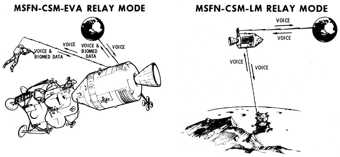
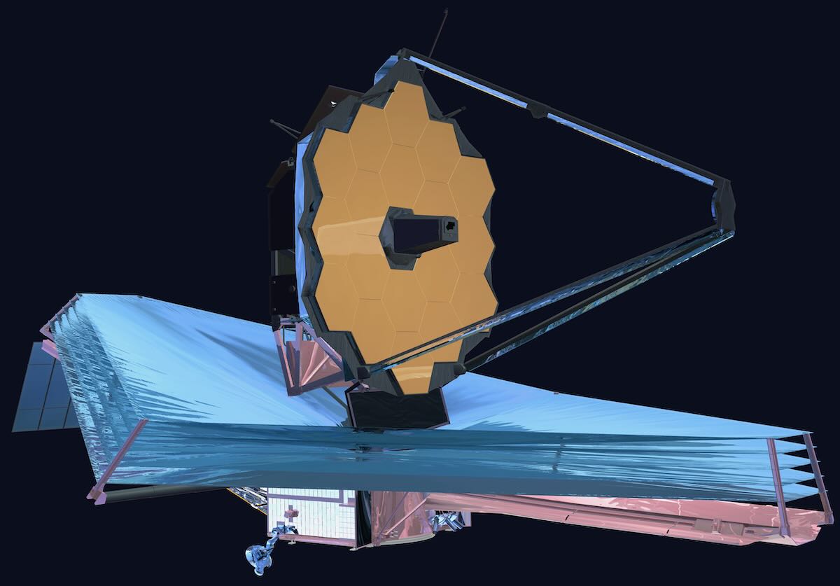
The James Webb Space Telescope probably needs no introduction, since it is perhaps the most important and well-known mission of the last years. It was launched on Christmas day from Kourou, French Guiana, into a direct transfer orbit to the Sun-Earth L2 Lagrange point. JWST uses S-band at 2270.5 MHz to transmit telemetry. The science data will be transmitted in K-band at 25.9 GHz, with a rate of up to 28 Mbps.

After launch, the first groundstation to pick the S-band signal from JWST was the 10 m antenna from the Italian Space Agency in Malindi, Kenya. This groundstation commanded the telemetry rate to increase from 1 kbps to 4 kbps. After this, the spacecraft’s footprint continued moving to the east, and it was tracked for a few hours by the DSN in Canberra. One of the things that Canberra did was to increase the telemetry rate to 40 kbps, which apparently is the maximum to be used in the mission.

As JWST moved away from Earth, its footprint started moving west. After Canberra, the spacecraft was tracked by Madrid. Edgar Kaiser DF2MZ, Iban Cardona EB3FRN and other amateur observers in Europe received the S-band telemetry signal. When Iban started receiving the signal, it was again using 4 kbps, but some time after, Madrid switched it to 40 kbps.

At 00:50 UTC on December 26, the spacecraft made its first correction burn, which lasted an impressive 65 minutes. Edgar caught this manoeuvre in the Doppler track.

Later on, between 7:30 and 11:30 UTC, I have been receiving the signal with one of the 6.1 metre dishes at Allen Telescope Array. The telemetry rate was 40 kbps and the spacecraft was presumably in lock with Goldstone, though it didn’t appear in DSN now. I will publish the recording in Zenodo as usual, but since the files are rather large I will probably reduce the sample rate, so publishing the files will take some time.

In the rest of this post I give a description of the telemetry of JWST and do a first look at the telemetry data. [Continue reading…]

Helping Secure Amateur Radio’s Digital Future (Hackaday)

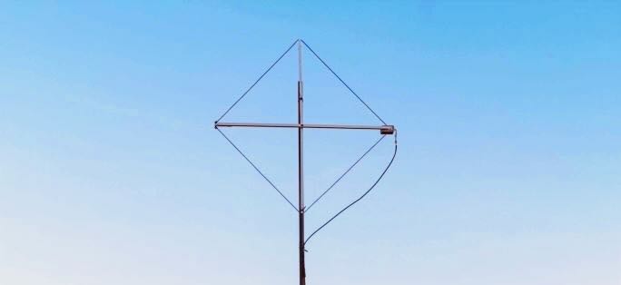
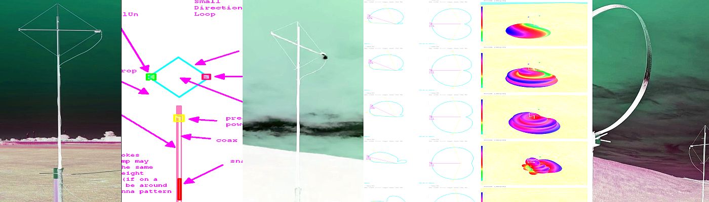
The average person’s perception of a ham radio operator, assuming they even know what that means, is more than likely some graybeard huddled over the knobs of a war-surplus transmitter in the wee small hours of the morning. It’s a mental image that, admittedly, isn’t entirely off the mark in some cases. But it’s also a gross over-simplification, and a generalization that isn’t doing the hobby any favors when it comes to bringing in new blood.

In reality, a modern ham’s toolkit includes a wide array of technologies that are about as far away from your grandfather’s kit-built rig as could be — and there’s exciting new protocols and tools on the horizon. To ensure a bright future for amateur radio, these technologies need to be nurtured the word needs to be spread about what they can do. Along the way, we’ll also need to push back against stereotypes that can hinder younger operators from signing on.

On the forefront of these efforts is Amateur Radio Digital Communications (ARDC), a private foundation dedicated to supporting amateur radio and digital communication by providing grants to scholarships, educational programs, and promising open source technical projects. For this week’s Hack Chat, ARDC Executive Director Rosy Schechter (KJ7RYV) and Staff Lead John Hays (K7VE) dropped by to talk about the future of radio and digital communications. [Continue reading…]

Interference causes EV makers to drop AM radio (Radio World via the Southgate ARC)

Radio World reports the Electromagnetic Interference generated by Electric Vehicles is causing some EV automakers to drop AM (medium wave) radio

The article says:

Some EV automakers are dropping AM altogether due to audio quality concerns, but that’s just one piece of the puzzle as radio continues to fight for space on the dash.

“As carmakers increase electric vehicle offerings throughout their lineups, the availability of AM radio to consumers is declining,” said Pooja Nair, communications systems engineer with Xperi Corp., in a Radio World guest commentary. “This is because the effects of electromagnetic interference are more pronounced in EVs than in vehicles with internal-combustion engines.”

In other words, electromagnetic frequencies generated by EV motors occupy the same wavelength as AM radio signals. The competing signals clash, effectively cancelling each other out. As EV motors grow more powerful, AM static tends to increase.

Read the full story at
https://www.radioworld.com/news-and-business/headlines/why-are-some-automakers-ditching-am-radio


Do you enjoy the SWLing Post?

Please consider supporting us via Patreon or our Coffee Fund!

Your support makes articles like this one possible. Thank you!

Spread the radio love

Ken reverse-engineers the Apollo spacecraft’s FM radio

Many thanks to SWLing Post contributor, Paul, who shares the following post from Ken Shirriffs’ Blog:

Reverse-engineering the Apollo spacecraft’s FM radio

How did NASA communicate with the Apollo astronauts, hundreds of thousands of miles from Earth? The premodulation processor1 (below) was the heart of the communication system onboard the Apollo spacecraft. Its multiple functions included an FM radio for communication to the astronauts, implemented by the Voice Detector, the module second from the top. In this blog post, I reverse-engineer the circuitry for that module and explain how it worked.

The Apollo communication system was complex and full of redundancy. Most communication took place over a high-frequency radio link that supported audio, telemetry, scientific data, and television images.2 NASA’s massive 85-foot dish antennas transmitted signals to the spacecraft at 2106.4 megahertz, an S-band frequency, giving the system the name “Unified S-Band”. These radio signals were encoded using phase modulation;3 onboard the spacecraft, a complex box called the transponder received the S-band signal and demodulated it.4

The voice and data signals from Earth were combined through a second layer of modulation: voice was frequency-modulated (FM) onto a 30-kilohertz subcarrier while data was on a 70-kilohertz subcarrier, so the two signals wouldn’t conflict.5 One of the tasks of the premodulation processor was to extract the voice and data signals from the transponder’s output. These voice signals went to yet another box, the Audio Center Equipment, so the astronauts could hear the messages from the ground. The data signals were decoded by the Up-Data Link, allowing NASA to send commands to the Apollo Guidance Computer, control onboard relays, or set the spacecraft’s clock.

Many systems worked together for communication, but I’m focusing on a single module: the voice detector inside the premodulation processor that performed the FM demodulation. [Continue reading the full article…]

Spread the radio love

Jock gets a good grounding!

Many thanks to SWLing Post contributor, Jock Elliott, who shares the following guest post:


Getting grounded – at last!

By Jock Elliott, KB2GOM

Readers’ comments are among the best things about writing for the SWLing.com blog. When a reader responds to a post and leaves a comment, it does three things. First, it lets the author know that someone actually read the post. Second, it provides valuable feedback – “I liked it.” “Did you know about this . . .?” “I had a similar experience.” – and so forth. Finally, it provides the author an opportunity to learn something, and that perhaps is the most fun.

A case in point: when I posted this, Andrew (grayhat) said:

“If you want to make an experiment, connect the end-fed to the Satellit high-Z wire input (clamp), then pick a (relatively short) run of insulated wire connect one end of the wire to the high-Z “ground” (clamp) and the other end of that wire to the “gnd” hole in the wall plug

The above being said, I prefer keeping antennas outside and taking care of the feedline, this helps reducing or eliminating noise from indoor appliances like switching PSUs and other things, anyway, if you want, try the above idea and let me know how it works for you”

To which, I responded:

“Thanks for the comments.

Thanks to a tree falling on the powerlines, I now know that the inherent electrical noise in my radio room is basically down to the level of atmospheric noise.

Neverthless, experimenting with a ground is definitely worth trying. A thin wire, sneaked out the window to a ground rod, might do the trick. I’ll report back after I try.”

Andrew (grayhat) came back to me and said:

“I was serious, try the “wall plug ground” I described, it won’t start any “magic smoke” or the like, otherwise, if you can lay out a wire with a length of 5m max, cut to be NON resonant, and connected to a good ground stake, go for it

Then, if you want to discuss this further, just ask Thomas for my e-mail, I agree to share it with you.”

Now, I really appreciated Andrew’s comments, but what I had not told him was that there is just one wall plug in my radio shack; it is really inaccessible, and I am not sure I can get a ground off it. Further, the rest of the power “system” in my shack is a rat’s nest of power bars and extensions, and I have zero confidence that any of them will provide a useful ground.

But – and this is a big but – I did take Andrew’s point: that connecting an actual ground to the ground clip on the back of the Satellit 800 might improve things. Continue reading

Spread the radio love

Radio Waves: DRM Part of BBC Story, Antennas and Smith Charts, Shortwave “Hot Debate,” Carrington Event, and “Deep Freeze”

Radio Waves:  Stories Making Waves in the World of Radio

Welcome to the SWLing Post’s Radio Waves, a collection of links to interesting stories making waves in the world of radio. Enjoy!


DRM Is Part of the BBC World Service Story (Radio World)

The iconic broadcaster has been supportive of the standard for over 20 years

The author is chairman of the DRM Consortium. Her commentaries appear regularly at radioworld.com.

Our old friend James Careless studiously ignores DRM once more in his well-researched, but to our minds incomplete article “BBC World Service Turns 90” in the March 30 issue.

As an ex-BBC senior manager, I would like to complete the story now that the hectic NAB Show is over.

Having lived through and experienced at close quarters the decision to reduce the BBC shortwave about 20 years ago, I can confirm that the BBC World Service decision to cut back on its shortwave footprint — especially in North America, where reliable, easy-to-receive daily broadcasts ceased — has generated much listener unhappiness over the years.

In hindsight, the decision was probably right, especially in view of the many rebroadcasting deals with public FM and medium-wave stations in the U.S. (and later other parts of the world like Africa and Europe) that would carry news and programs of interest to the wide public.

But BBC World Service in its long history never underestimated the great advantages of shortwave: wide coverage, excellent audio in some important and populous key BBC markets (like Nigeria) and the anonymity of shortwave, an essential attribute in countries with undemocratic regimes.

BBC World Service still enjoys today about 40 million listeners worldwide nowadays. [Continue reading…]

The Magic of Antennas (Nuts & Volts)

If you really want to know what makes any wireless application work, it is the antenna. Most people working with wireless — radio to those of you who prefer that term — tend to take antennas for granted. It is just something you have to add on to a wireless application at the last minute. Well, boy, do I have news for you. Without a good antenna, radio just doesn’t work too well. In this age of store/online-bought shortwave receivers, scanners, and amateur radio transceivers, your main job in getting your money’s worth out of these high-ticket purchases is to invest a little bit more and put up a really good antenna. In this article, I want to summarize some of the most common types and make you aware of what an antenna really is and how it works.

TRANSDUCER TO THE ETHER
In every wireless application, there is a transmitter and a receiver. They communicate via free space or what is often called the ether. At the transmitter, a radio signal is developed and then amplified to a specific power level. Then it is connected to an antenna. The antenna is the physical “thing” that converts the voltage from the transmitter into a radio signal. The radio signal is launched from the antenna toward the receiver.

A radio signal is the combination of a magnetic field and an electric field. Recall that a magnetic field is generated any time a current flows in a conductor. It is that invisible force field that can attract metal objects and cause compass needles to move. An electric field is another type of invisible force field that appears between conductors across which a voltage is applied. You have experienced an electric field if you have ever built up a charge by shuffling your feet across a carpet then touching something metal … zaaapp. A charged capacitor encloses an electric field between its plates.

Anyway, a radio wave is just a combination of the electric and magnetic fields at a right angle to one another. We call this an electromagnetic wave. This is what the antenna produces. It translates the voltage of the signal to be transmitted into these fields. The pair of fields are launched into space by the antenna, at which time they propagate at the speed of light through space (300,000,000 meters per second or about 186,000 miles per second). The two fields hang together and in effect, support and regenerate one another along the way. [Continue reading…]

Smith Chart Fundamentals (Nuts & Volts)

The Smith Chart is one of the most useful tools in radio communications, but it is often misunderstood. The purpose of this article is to introduce you to the basics of the Smith Chart. After reading this, you will have a better understanding of impedance matching and VSWR — common parameters in a radio station.

THE INVENTOR
The Smith Chart was invented by Phillip Smith, who was born in Lexington, MA on April 29, 1905. Smith attended Tufts College and was an active amateur radio operator with the callsign 1ANB. In 1928, he joined Bell Labs, where he became involved in the design of antennas for commercial AM broadcasting. Although Smith did a great deal of work with antennas, his expertise and passion focused on transmission lines. He relished the problem of matching the transmission line to the antenna; a component he considered matched the line to space. Continue reading

Spread the radio love