Shortwave listening and everything radio including reviews, broadcasting, ham radio, field operation, DXing, maker kits, travel, emergency gear, events, and more
Many thanks to SWLing Post contributor, Frans Goddijn, who writes:
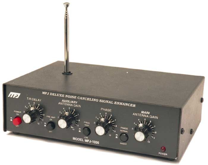
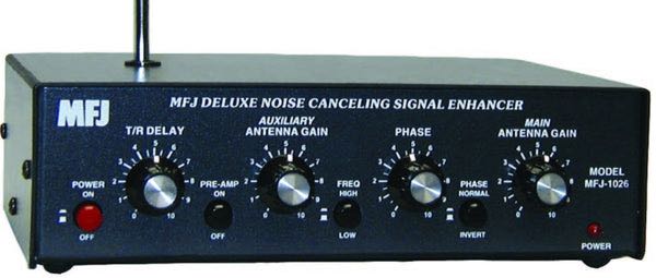
“Last week I purchased the MFJ-1026 ‘noise canceling signal enhancer’ and I posted two blogs with video about it. Initially the device seemed as useless as it is good looking but then I found a configuration where the device is not only pleasant to have but also useful for radio listening.”
Here are Frans’ reports which he kindly shares from thesetwo posts originally published on his blog, Kostverlorenvaart:
Part 1: MFJ-1026 deluxe noise canceling signal enhancer
Using a GRAHN antenna, (a VENHORST wire antenna for noise reference), the iCOM R8600 radio and optional bhi DSP audio noise canceling, trying to see what’s the best way to cancel noise — on the antenna entry point of the radio or at the speaker output end.
In this case the MFJ-1026 seems ineffective. The DSP at the audio output end works well and easy.
I have also tried two GRAHN antennas on the MFJ-1026, one for MAIN and one for AUX but that was also not noticeably effective yet.
I will also try the little whip antenna that MFJ supplied with the box. Further tweaking may turn out to be helpful on some other frequencies / signals.
Before installing the MFJ i used the little TECSUN H-501x to scan the room for any devices producing radio noise. It turned out that the two Apple Homepods sit in a dense cloud of radio noise, the Macbook Pro also radiates noise, EVE smart plugs controlling lights also produce radio noise, two little label printers s well and the HP printer/scanner too. So I moved those to the other end of the toom or to another room. Continue reading →
My VERY NOISY Sony CRT TV has gone to the great electronics recycling bin in the sky thank goodness. But I still have a MFJ-1026 here and need to use it when the neighborhood gets noisy. Intermittent power line noise is the main issue these days for me.
[Note that] my Monitoring Times review from April 2007 on the MFJ-1026 (and 1025 model without the preamp, but is best to have it) is still available here :
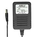
I still power it with a analog REGULATED Jameco 170245 12 volt (1 amp) ac adapter.
Last batch I purchased a few years ago were still 100% clean and analog regulation. As I have covered in the past, SOME of Jameco excellent REGULATED AC adapters have gone to using switching regulator devices inside (and these no longer clean for any radio use).
DX Engineering is about to come out with a improved version of the premium priced NCC-1, called the NCC-2. Mid late November Delivery ?? Never had our hands on one the pricey NCC-1 critters as the MFJ gets the job done for us (let alone affording it).
In a previous guest post, SWLing Post contributor TomL, shared his “Evolving, Morphing, SW Listening Station” where he detailed the many ways he’s trying to fight heavy radio interference at his listening post. The following post is TomL’s update:
More Anti-Noise Ideas
(Continuing the hunt for better reception in a foul RFI environment)
by TomL
I have made the following changes:
Created a prototype mini-loop based on a crossed-parallel idea from VE1ZAC (Jeff).
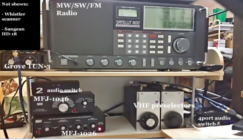
Added 2 preselectors, an old Grove TUN-3 connected to the main loop feed and an MFJ-1046 connected to the ground connection of the balun. Both feeds go into the MFJ-1026.
Added a medium wave noise canceling unit that I have not figured out how to use yet. (Quantum Phaser). The MFJ unit does not work on medium wave without modification.
Purchased from eBay a used Grundig Satellit 800, a somewhat more robust fixed-station receiver to replace my aging Sony ICF-2010.
Other non-related (not shown): Whistler digital scanner + UHF over-the-air TV + FM broadcasts + an AM/FM HD digital radio + high pass filters from MiniCircuits.com – (audio from all these sources is passed to an existing high fidelity stereo power amp and NHT Super One speakers on the computer desk for near-field monitoring). Associated antennas are also hidden on the outside deck (shhhhh!).
Large charge card balance!!
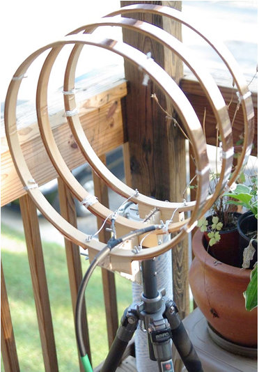
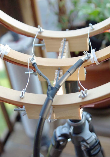
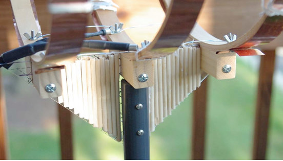
So, here are some pics for the crossed-parallel loop. VE1ZAC web site has all the references if you want to explore further or google him. Mine is purely a prototype and not finished. And should eventually be placed on a rotor (but how to keep my Nazi-like condo association from finding out?!?!?!?).
It is three 14 inch quilters hoops from Joann Stores plus some 1-inch copper strips cut from a small 2 meter roll of thin copper from eBay. Then, it is wired in parallel with silver-plated aviation wire on each side with a feed in the middle. Not an optimal placement of the feed, (should go straight down along the pipe). Will fix things up whenever I get some more time.
Seems to be an efficient way to prototype small loops. It is now mounted on a short ¾” inside diameter PVC pipe into a cheap plastic sand-filled deck-umbrella stand. Loops are light and somewhat flimsy, so I mounted the three loops on a plastic triangle ruler and dowel sticks glued to the sides for some extra strength. Good enough for now.
The EF-SWL balun is also in an experimental configuration. Since I read somewhere that loop antennas have a very low impedance at the feed point (like, 10 ohms or lower), I thought I might try a balun that is meant to lower the impedance and mount it backwards. I don’t have a picture of it but the SO-239 output is facing the loop and the screw terminals are facing the direction of the radio. My feeble brain thinks since it is a passive device of coils on ferrite, it should work bidirectionally for receive only applications like this. It seems to work but I have the excuse that I really don’t know what I am doing! 🙂
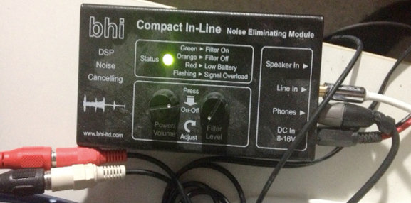
BHI unit in action.
The BHI DSP filter is useful in some circumstances but I find it fatiguing to listen to. The audio from the Sattelit 800 is so nice, I mostly like it without the DSP. The DSP narrows the bandwidth significantly, somewhere around 4 kHz or less from my hearing. I like that the Grundig has two tone controls. And it also has a stable SSB and on very strong signals with clear audio, I like to listen with SSB lower or upper sideband. But the DSP is useful at times for hash-like noisy signals; it is not quite as good on buzzing noise and I wish the Satellit 800 had a noise blanker, but that would have been a more costly purchase, like a Drake R8A.
So, in a nutshell, I have a discovery about noise here: it is all around me and ubiquitous, like the air I breathe!
I find it hard to null and also worry about peaking a station signal at the same time. However, I do have a lower noise floor with the experimental loop sitting outdoors, especially on medium wave (the Wellbrook amp + loop works great on the lower frequencies – am able to get eight different medium wave stations carrying Major League Baseball games at night – it would be nine to get WFAN for the New York Mets but the local Chicago Cubs station covers the adjacent frequency with horrible digital hash! ***Bleeping*** digital junk!).
Also, the signal level is noticeably lower using the loop. Then, add in the effect of the MFJ Noise Canceling unit, the usable signal gets even weaker.
The bottom line is, I can now finally enjoy listening to many SW broadcasts, BUT only the strongest signals. Anything else is still hopelessly lost in the noise. So, gains are limited.
On the other hand, and something else I learned by doing is that, any 1 or 2 dB signal/noise ratio improvement will help with the final audio output in the end product. Using low-noise amps, loops, noise canceler, preselectors, grounded connections, ground isolators at the input of every receiver, high quality stereo amplifier and speakers, tone controls, SSB vs. AM Sync, weird antenna configurations, etc, etc. It all helps in the end to some degree.
Tinkering is an art that involves a lot of thinking/doing iterations! And high quality parts must be used all along the chain or it could degrade the signal.
Below are some audio samples, not very well recorded, but can give some idea of the incremental improvement with each enhancement (turn up the volume). NOTE: other people may get better or worse results depending upon individual situations, type of antennas used, etc, etc.
Recording 1: R. Marti. First 10 seconds an indoor antenna with no noise reduction, second 10 seconds the outdoor loop without the MFJ-1026, the third 10 seconds with the MFJ-1026, then switched off and on to hear the difference.
Recording 2: R. Marti. MFJ -1026 is ON. Last 15 seconds is SSB, very thin sounding. Really only good for strongest signals. I liked the AM Sync better (Satellit 800 is really a Drake SW8 in disguise with a quality AM Sync). But, SSB can sound excellent with very clear voices with a steady and strong signal (The Satellit 800 does NOT have IF-shift or a BFO to fine tune an SSB reception, so the station must be exactly transmitting on the kHz mark, which most are nowadays).
Recording 3: R. Marti. MFJ-1026 is ON. Last 20 seconds you hear me switch in the two audio switches and the BHI DSP is on its lowest setting. Narrower and clearer with some reduction of background noise. I find I only like going up to about 4 on the DSP dial, after that the audio fidelity starts getting more choppy with digital artifacts that sound like dripping water. I tend to like higher fidelity. One nice thing about the BHI DSP is a faux-stereo that helps a little with voice intelligibility by helping the brain naturally filter the noise. Faux-stereo is ON even when the noise reduction circuit is manually turned off (power must be on and bandwidth still sounds narrowed).
Recording 4: R. Nacional Brazilia. First without MFJ-1026, then ON, then OFF, then ON, then with the BHI kicked for the last 20 seconds.
Recording 5: Greece. Switching the MFJ-1026 on and off every 5 seconds. In this particular case, the signal was weak and fading a lot. The MFJ OFF was also weaker than with it turned ON. That is interesting behavior, usually it is opposite. It pays to play with the settings a little. At other times, and less frequently, the MFJ unit turned OFF sometimes sounds better than with it ON and tuned for less noise. Go figure!
After all the tweaking is done, and I cannot get any more performance out of this, I will probably have to move to a nice, quiet neighborhood and setup a nice antenna farm!!
In the meantime, I do enjoy listening to the stronger stations from North America, Cuba, Brazil, Europe, and Australia with less noise than before.
73’s
TomL from NOIZEY Illinoiz
Once again, Tom, thanks for sharing your RFI elimination journey!
I love how you take on this noisy problem by experimenting and seeing it more as a challenge than an obstacle to enjoying your hobby. Great job!
Many thanks to SWLing Post contributor, London Shortwave, who is kindly sharing this guest post–a brilliant article he recently posted on his own website.
I’m very grateful: one of the most common questions I’m asked by readers is how to cope with the radio interference so many listeners and amateur radio operators experience in high-density, urban areas. If this is you, you’re in for a treat–just keep reading:
Dealing with Urban Radio Interference on Shortwave
Shortwave radio listening is an exciting hobby, but for many of us city dwellers who either got back into it recently or tried it out for the first time not long ago, the first experience was a disappointing one: we could barely hear anything! Station signals, even the supposedly stronger ones, were buried in many different types of static and humming sounds. Why does this happen? The levels of urban radio frequency interference, or RFI, have increased dramatically in the last two decades and the proliferation of poorly engineered electronic gadgets is largely to blame. Plasma televisions, WiFi routers, badly designed switching power adapters and Ethernet Over Powerlines (also known as powerline network technology, or PLT) all severely pollute the shortwave part of the radio spectrum.
Does this mean we should give up trying to enjoy this fascinating medium and revert to using the TuneIn app on our smartphones? Certainly not! There are many angles from which we can attack this problem, and I shall outline a few of them below.
Get a good radio
The old adage “you get what you pay for” certainly holds true even when it comes to such “vintage” technologies as shortwave radio. Believe it or not, a poorly designed receiver can itself be the biggest source of noise on the bands. That is because many modern radios use embedded microprocessors and microcontrollers, which, if poorly installed, can generate interference. If the receiver comes with a badly designed power supply, that too can generate a lot of noise.
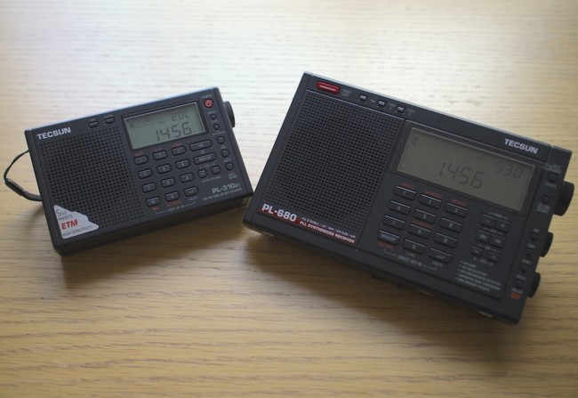
So how does one go about choosing a good radio? SWLing.com and eHam.net have fantastic radio review sections, which will help you choose a robust receiver that has withstood the test of time. My personal favourites in the portable category are Tecsun PL310-ET and Tecsun PL680. If you want a desktop radio, investigate the type of power supply it needs and find out whether you can get one that generates a minimal amount of noise.
It is also worth noting that indoor shortwave reception is usually best near windows with at least a partial view of the sky.
Tecsun PL310-ET and Tecsun PL680, my two favourite portable shortwave radios.
Identify and switch off noisy appliances
Many indoor electrical appliances generate significant RFI on the shortwave bands. Examples include:
Plasma televisions
Laptop, and other switching-type power supplies
Mobile phone chargers
Dimmer switches
Washing machines / dishwashers
Amplified television antennas
Halogen lighting
LED lighting
Badly constructed electrical heaters
Mains extension leads with LED lights
Identify as many of these as you can and switch them all off. Then turn them back on one by one and monitor the noise situation with your shortwave radio. You will most likely find at least a few offending devices within your home.
Install an outdoor antenna
If you have searched your home for everything you can possibly turn off to make reception less noisy but aren’t satisfied with the results, you might want to look into installing and outdoor antenna. That will be particularly effective if you live in a detached or a semi-detached property and have a garden of some sort. Of course, you will need a radio that has an external antenna input, but as for the antenna itself, a simple copper wire of several metres will do. An important trick is making sure that the noise from inside your home doesn’t travel along your antenna, thus negating the advantage of having the latter installed outside. There are many ways of achieving this, but I will suggest a configuration that has worked well for me in the past.
Fig.1 Schematic for an outdoor dipole antenna.
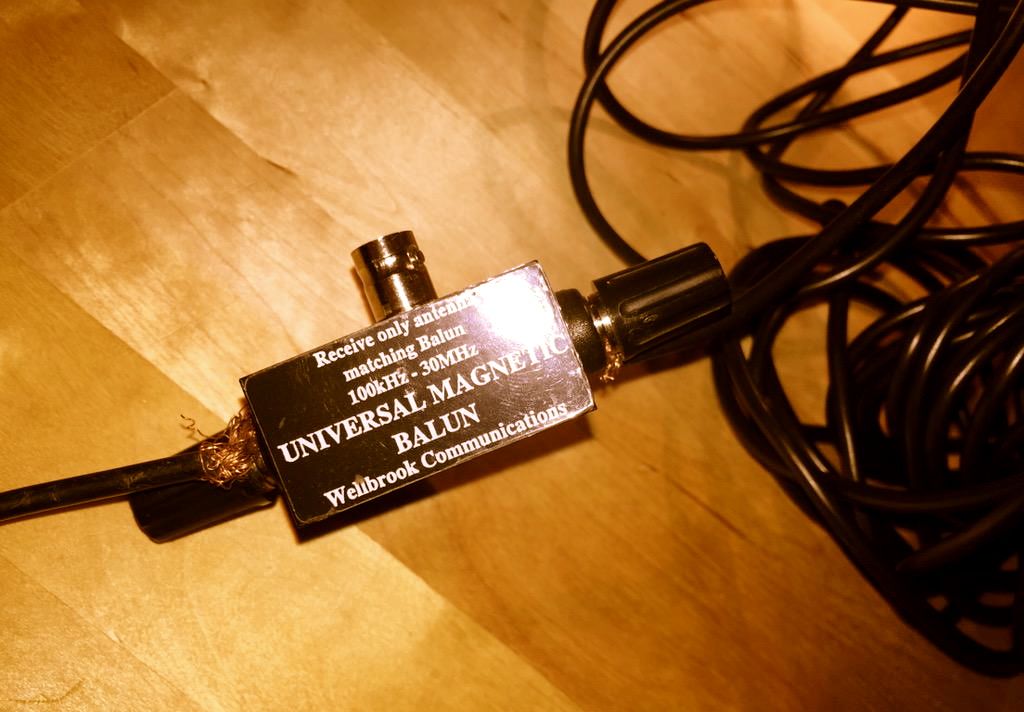
I have used a three-terminal balun (positioned outdoors), and connected two 6 metre copper wires to its antenna terminals to create a dipole. I then connected the balun to the radio indoors through the feed line terminal using a 50? coaxial cable. In the most general terms, the current that is generated in the antenna wires by the radio waves flows from one end of the dipole into the other, and a portion of this current flows down the feed line into your radio. The balun I have used (Wellbrook UMB130) is engineered in a way that prevents the radio noise current from inside your house flowing into the receiving part of the antenna.
Wellbrook UMB130 balun with the feed line terminal disconnected
Antenna preselectors
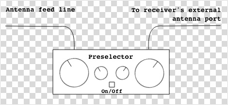
There is a catch with using an outdoor antenna described above — the signals coming into your radio will be a lot stronger than what would be picked up by the radio’s built-in “whip” antenna. This can overload the receiver and you will then hear many signals from different parts of the shortwave spectrum “mixing in” with the station you are trying to listen to. An antenna preselector solves this problem by allowing signals from a small yet adjustable part of the spectrum to reach your radio, while blocking the others. You can think of it as an additional tuner that helps your radio reject unwanted frequencies.
Fig.2 Schematic of a preselector inserted between the outdoor antenna and the receiver
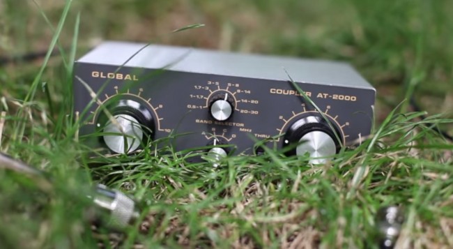
There are many antenna preselectors available on the market but I can particularly recommend Global AT-2000. Although no longer manufactured, many used units can be found on eBay.
Global AT-2000 antenna coupler and preselector
Risk of lightning
Any outdoor antenna presents the risk of a lightning strike reaching inside your home with devastating and potentially lethal consequences. Always disconnect the antenna from the receiver and leave the feed line cable outside when not listening to the radio or when there is a chance of a thunderstorm in your area.
Get a magnetic loop antenna
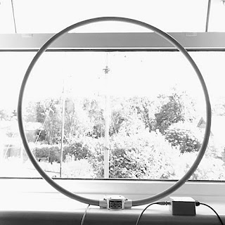
A broadband loop antenna (image courtesy of wellbrook.uk.com)
The outdoor long wire antenna worked well for me when I stayed at a suburban property with access to the garden, but when I moved into an apartment well above the ground floor and without a balcony, I realised that I needed a different solution. Having googled around I found several amateur radio websites talking about the indoor use of magnetic loop receive-only active antennas (in this case, “active” means that the antenna requires an input voltage to work). The claim was that such antennas respond “primarily to the magnetic field and reject locally radiated electric field noise”[*] resulting in lower noise reception than other compact antenna designs suitable for indoor use.
Interlude: signal to noise ratio
In radio reception, the important thing is not the signal strength by itself but the signal to noise ratio, or SNR. A larger antenna (such as a longer copper wire) will pick up more of the desired signal but, if close to RFI sources, will also pick up disproportionately more of the local noise. This will reduce the SNR and make the overall signal reading poorer, which is why it is not advisable to use large antennas indoors.
The other advantage of a loop antenna is that it is directional. By rotating the loop about its vertical axis one can maximise the reception strength of one particular signal over the others, once the antenna is aligned with the direction from which the signal is coming (this is termed “peaking” the signal). Similarly, it is possible to reduce the strength of a particular local noise source, since the loop is minimally sensitive to a given signal once it is perpendicular the latter’s direction (also known as “nulling” the signal).
It is further possible to lower the effect of local noise sources by moving the antenna around. Because of the antenna’s design, the effect of radio signals is mostly confined to the loop itself as opposed to its feed line. Most local noise sources have irregular radiation patterns indoors, meaning that it is possible find a spot inside your property where their effects are minimised.
Many compact shortwave loop antennas require an additional tuning unit to be attached to the loop base (much like the preselector described above) but broadband loops do not. Wellbrook ALA1530S+ is one such antenna that is only 1m in diameter, and it was the one I chose for my current apartment. I was rather impressed with its performance, although I found that I need to use a preselector with it as the loop occasionally overloads some of my receivers when used on its own. Below is a demo video comparing using my Tecsun PL680’s built-in antenna to using the radio with the Wellbrook loop.
As you can hear, there is a significant improvement in the signal’s readability when the loop is used.
Experiment with a phaser
Although the loop antenna dramatically reduces the levels of ambient RFI getting into the radio, I also have one particular local noise source which is way too strong for the loop’s nulling capability. Ethernet Over Powerlines (PLT) transmits data across domestic electrical circuits using wall socket adapters, as an alternative to wireless networking. It uses the same frequencies as shortwave, which turns the circuits into powerful transmitting antennas, causing massive interference. One of my neighbours has PLT adapters installed at his property, which intermittently become active and transmit data. When this happens, it is not merely noise that is generated, but a very intense data signal that spreads across the entire shortwave spectrum, obliterating everything but the strongest stations underneath. Fortunately, a mature piece of radio technology called antenna phasing is available to deal with this problem.
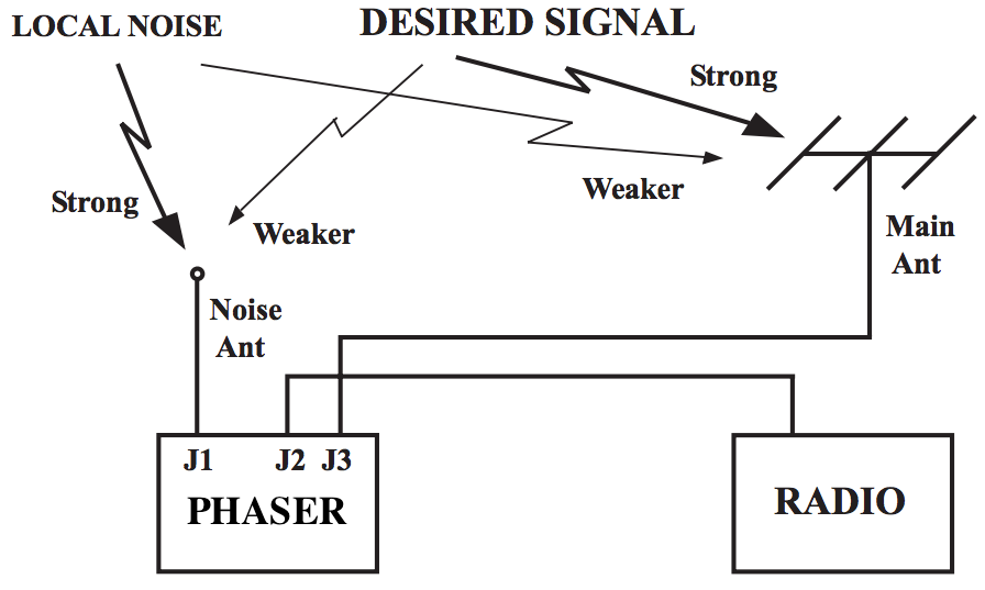
Fig.3 The principle of antenna phaser operation (adapted from an original illustration in Timewave ANC-4’s manual)
Signal cancellation using phase difference
A phaser unit has two separate antenna inputs and provides one output to be connected to the radio’s external antenna input. The theory of phase-based signal cancellation goes roughly as follows:
The same radio signal will arrive at two different, locally separated antennas at essentially the same time.
The phase of the signal received at the first antenna will be different to the phase of the same signal received at the second antenna.
This phase difference depends on the direction from which the signal is coming, relative to the two antennas.
The phaser unit can shift the phases of all signals received at one antenna by the same variable amount.
To get rid of a particular (noise) signal using the phaser unit:
the signal’s phase at the first antenna has to be shifted by 180° relative to the signal’s phase at the second antenna (thus producing a “mirror image” of the signal received at the second antenna)
its amplitude at the first antenna has to be adjusted so that it is the same as the signal’s amplitude at the second antenna
the currents from the two antennas are then combined by the unit, and the signal and its mirror image cancel each other out at the unit’s output, while the other signals are preserved.
Noise sampling antenna considerations
To prevent the possibility of the desired signal being cancelled out together with the noise signal — which can happen if they both come from the same direction relative to the antennas — one can use the set-up illustrated in Figure 3, where one antenna is dedicated to picking up the specific noise signal, while the other is geared towards receiving the desired broadcast. That way, even if the phases of both the noise and the desired signals are offset by the same amount, their relative amplitude differences will not be the same, and thus removing the noise signal will not completely cancel out the desired signal (though it will reduce the latter’s strength to some extent).
It is possible to use any antenna combination for phase-based noise signal cancellation. However, one has to be careful that, in the pursuit of removing a specific noise source, one does not introduce more ambient RFI into the radio system by using a poorly designed noise-sampling antenna. After all, the phaser can only cancel out one signal at a time and will pass through everything else picked up by both antennas. This is particularly relevant in urban settings.
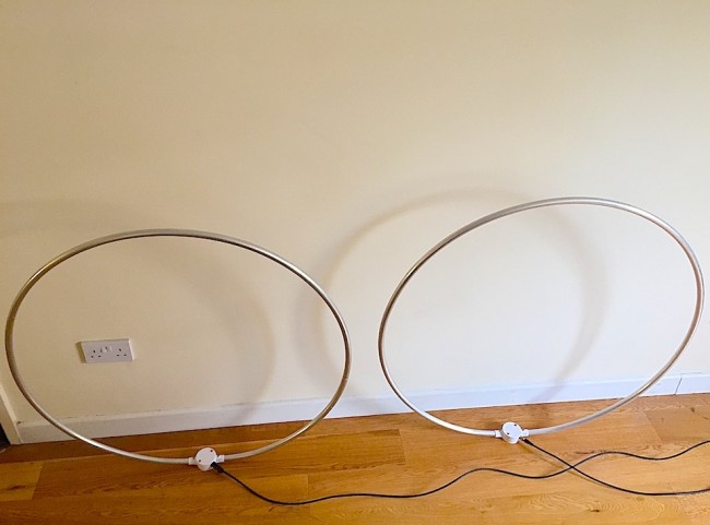
For this reason, I chose my noise sampling antenna to also be a Wellbrook ALA1530S+. The additional advantages of this set-up are:
It is possible to move both loops around to minimise the amount of ambient RFI.
By utilising the loops’ directionality property, one can rotate the noise sampling loop to maximise the strength of the noise signal relative to the desired signal picked up by the main antenna loop.
Two Wellbrook ALA1530S+ antennas combined through a phaser
And now onto the phaser units themselves.
Phaser units
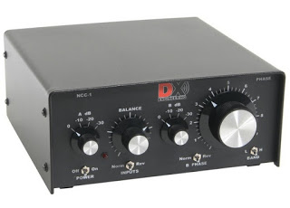
DX Engineering NCC-1 (image courtesy of dxengineering.com)
I have experimented at length with two phaser units: the MFJ 1026 (manual) and DX Engineering NCC-1 (manual). Both solve the problem of the PLT noise very well, but the NCC-1 offers amplitude and phase tuning controls that are much more precise, making it a lot easier to identify the right parameter settings. Unfortunately this comes at a price, as the NCC-1 is a lot more expensive than the MFJ unit. As before, a preselector is needed between the phaser and the radio to prevent overloading.
Below is a demo of DX Engineering NCC-1 at work on my neighbour’s PLT noise. I have chosen to use my SDR’s waterfall display to illustrate the nefarious effect of this type of radio interference and to show how well the NCC-1 copes with the challenge.
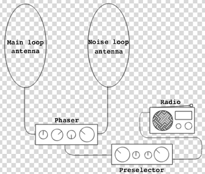
Cost considerations
Fig.4 Final urban noise mitigation schematic
It would be fair to say that my final urban noise mitigation set-up, shown in Figure 4, is quite expensive: the total cost of two Wellbrook antennas ($288.38 each), a DX Engineering phaser ($599.95) and a Global AT2000 preselector ($80) comes to $1257. That seems like an astronomical price to pay for enjoying shortwave radio in the inner city! However, at this point another old saying comes to mind, “your radio is only as good as your antenna”. There are many high-end shortwave receivers that cost at least this much (e.g. AOR AR7030), but on their own they won’t be of any use in such a noisy environment. Meanwhile, technological progress has brought about many much cheaper radios that rival the older benchmark rigs in terms of performance, with Software Defined Radios (SDRs) being a particularly good example. It seems fair, then, to invest these cost savings into what makes shortwave listening possible. You may also find that your RFI situation is not as dire as mine and you only need some of the above equipment to solve your noise problems.
Filter audio with DSP
If you have implemented the above noise reduction steps but would still like a less noisy listening experience, consider using a Digital Signal Processing (DSP) solution. There are a number of different approaches and products available on the market, and I shall be reviewing some of them in my next post. Meanwhile, below are two demo videos of using DSP while listening to shortwave. The first clip shows the BHI Compact In-Line Noise Elimination Module at work together with a vintage shortwave receiver (Lowe HF-150). The second video compares using a Tecsun PL-660 portable radio indoors on its own and using the entire RFI mitigation set-up shown in Figure 4 together with a DSP noise reduction feature available in the SDR# software package, while using it with a FunCube Dongle Pro+ SDR. As a side note, it is worth remembering that while DSP approaches can make your listening experience more pleasant, they can’t recover what has been lost due to interfering signals or inadequate antenna design.
Set up a wireless audio relay from your radio shack
The above RFI mitigation techniques can result in a rather clunky set-up that is not particularly portable, confining the listener to a specific location within their home. One way to get around this is by creating a wireless audio relay from your radio shack to the other parts of your house. I did this by combining the Nikkai AV sender/receiver pair and the TaoTronics BA01 portable Bluetooth transmitter:
Head for the outdoors!
So you have tried all of the above and none of it helps? As a last resort (for some, but personally I prefer it!), you can go outside to your nearest park with your portable radio. After all, if shortwave listening is causing you more frustration than joy it’s hardly worth it. On the other hand, you might be surprised by what you’ll be able to hear with a good receiver in a noise-free zone.
Acknowledgements
Many of the above tricks and techniques were taught to me by my Twitter contacts. I am particularly grateful to @marcabbiss, @SWLingDotCom, @K7al_L3afta and@sdrsharp for their advice and assistance over the years.
Thank you–!
What I love about my buddy, London Shortwave, is that he didn’t give up SWLing just because his home is inundated with radio interference–rather, he saw it as a challenge. As you can see, over the years, he has designed a system that effectively defeats radio interference.
I also love the fact that he uses an even more simple approach to defeating RFI: he takes his radio outdoors. A kindred spirit, indeed.
I encourage all SWLing Post readers to bookmark and search London Shortwave’s website. It’s a treasure trove for the urban SWL. We thank him for allow us to post this article in its entirety.
Spread the radio love
Please support this website by adding us to your whitelist in your ad blocker. Ads are what helps us bring you premium content! Thank you!

 Many thanks to SWLing Post contributor, Frans Goddijn, who writes: