Shortwave listening and everything radio including reviews, broadcasting, ham radio, field operation, DXing, maker kits, travel, emergency gear, events, and more
PC keyer and AM modulator: A 15-components versatile keyer and powerful PSU modulator for the EMTX (Emergency Transmitter)
by Kostas (SV3ORA)
Schematic of the keyer and modulator (on the left) for the EMTX. The EMTX schematic is shown as well on the right, to determine the connections to the keyer/modulator.
Introduction
My very successful emergency transmitter (EMTX) was only capable of CW or other slow speed ON/OFF keying modes. Then I thought, why not “give voice” to the design? CW is good, but it is half of the fun. If you could use your simple CW transmitter to send out your voice as well, this would be great. You could now chat comfortably on the nets or use any digital radio amateur mode and have much more fun. The simplest modulation you can apply to an existing CW transmitter, is the AM modulation. And whereas this is an old modulation, mostly abandoned by HAMs due to beeing inefficient, there are still AM nets on HF. But do not forget, AM can also be heard by SSB receivers by zero-beating the receiver to the AM carrier. So you could still use your simple AM transmitter to QSO with the SSB guys!
Along with the modulator, there is also a versatile keyer embedded to the circuit, so that the EMTX can be manually keyed with different ways or automatically keyed by audio tones from the PC. For more information on the keyer, keep reading.
The AM modulator
In the old days, the most common way to apply AM modulation was to modulate the high voltage to the plate of the tubes, using a transformer and a powerful audio amplifier. In low voltage solid state circuits, you can still do it using transformers, but you can also use series transistors instead of the transformer. All these things require many components and/or powerful AF amplifiers if one is to modulate higher power transmitters. This does not match the keep-it-simple design I am trying to achieve here.
So I thought of a simple trick with the use of the extremely common LM317 regulator, used as a modulated power supply. This modulator uses just a few common cheap components and it is able to achieve remarkably good modulation levels for it’s parts-count, just from line audio input. It juices every bit of the internal circuicity of the LM317, just look at where the base current of the 2N2222 comes from.
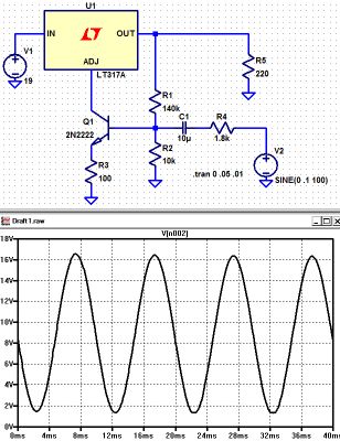
The AM modulator is a kind of novelty. Whereas there is nothing special in a modulated power supply, this circuit has some interesting properties. It is amazingly sensitive and it is able to provide lots of modulated current to any low power transmitter that it can feed. It can be easily driven by the line output of any laptop (around 20% volume) and provide a very good depth modulation to the transmitter. Charles Wenzel was kind enough to do a simulation on the circuit I developed, which is shown below.
His simulated circuit is a slight variation (for measurement purposes). The resistor to ground on the base stabilizes the bias and the ratio of R1 and R2 set the output voltage (0.6 volts across R2 gives about 8 volts across R1). He put in an emitter resistor just for good measure. Same for the series resistor from the source. Charles words, “I don’t know how believable these results are but it looks pretty darned good!”.
The circuit is being used as a current booster, the current being the supply to the transmitter and dependent on the voltage it produces. The LM317 always tries to keep 1.25V between it’s output pin and “adj” pin but where we benefit here is the current at the “adj” pin is very low, so it is easier to apply audio to it. Effectively, the error amplifier inside the voltage regulator is used as an additional amplifier stage. The output pin voltage varies according to the voltage on the “adj” pin so if we use it to bias the transistor we get negative feedback which improves the quality of the modulation. More output voltage = more bias current = lower output voltage. The result, is a very cheap, low components-count, very sensitive AM modulator that can supply lots of power to easily drive the transmitter and produce a clean and deep AM modulation!
The AM modulator bias is set with the 1M potentiometer. Depended on the bias level, the idle carrier on the EMTX can be set from about 0.5W all the way up to 8W. Needless to say that this modulator can modulate any similar power transmitter, not just the EMTX.
The keyer
If it is to modulate the EMTX from the PC, so as to use the different digital modes, there must be a way to key it also from the PC. This is why I decided to embed into the same circuit, a PC keyer which is triggered by the line audio of the PC, but also triggered manually (internal or external key). Keying by audio tones was decided, because modern PCs do not have LPT ports to trigger directly by DC. This keyer uses a reed relay to reliably, fastly and scilently key the EMTX, which is activated by a transistor. The base current for the transistor is derived from the audio signal after rectification. The incoming audio from the PC line passes through the mini audio transformer to increase its voltage, it is rectified and then charges the shunt capacitor to drive the base of the transistor. The keyer “speed” (decay) is determined by the shunt capacitor size. The circuit starts to trigger from about 50-60% of my sound card output signal level.
The relay used to key the EMTX, must be able to tolerate at least 1A of switching and carrying current. Note that the relay contacts switching current is not the same as the contacts carrying current. Reed relays are the best especially if you want long relay life, noiseless operation and very fast switching speeds, like the ones used in Hellshreiber. If you can’t find such a relay, you can use a reed switch capable of 1A of switching and carrying current and then place a suitable electromagnet close to it, so you can build the relay yourself. If you do so, find the best point where the reed switch responds to the electromagnet.
The keyer relay must be as close as possible to the emitter of the transistor used in the EMTX. The connectors at the back of the EMTX and the keyer/modulator have been physically placed so that when the two units are side by side, a very short link cable is required for this purpose. With the two devices placed close together, you can now use any length of cable for your manual external key, which is now connected to the “EXT” connector of the keyer/modulator.
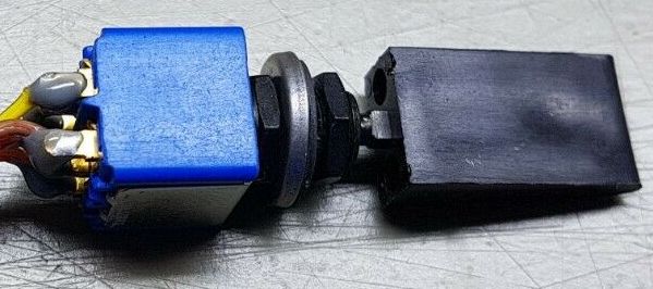
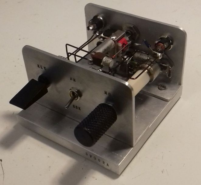
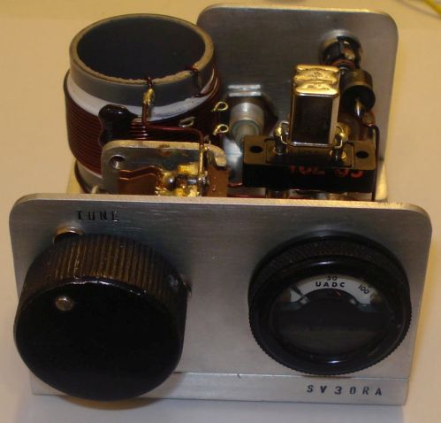
The keyer does also have an internal mini straight key. I find this idea very nice, to avoid extra cables. It is not the most convenient key in the world, but it is there along with the transmitter every time you need it. By using a special panel switch from apem, I was able to triple this switch usage for the different modes of the keyer. The vinyl lever cap you see in the next picture, is the original part of the switch, to make it easier to key with your finger. But you may build such a part on your own, to fit on other switches types.
The switch is an ON-OFF-(ON momentary) switch type. In the default (middle) position, only the PC keying action is activated. In the top position (ON), the keyer is always active, which is useful for broadcasting audio (into a dummy load). The bottom (ON momentary) position, is the manual PTT action. This is used as a straight key on OOK operation, or as a PTT on AM voice operation. Simple and effective!
Initially, I used one channel of the PC sound card for triggering the keyer and also as an AF signal for the AM modulator, but this caused several problems of unreliable keying or distortion. So I decided to use a second separate AF input (KAF) to key the keyer. This second input, uses the other channel of the stereo sound card. With the addition of this input, there is no interaction between the keyer and the modulator. The AF levels that the keyer and the modulator require, can be set independently. Instead of adding more hardware for the purpose, I have chosen to set these levels by adjusting the volume and the balance of the sound card, which works great. Also, programs like Fldigi, have options for using one of the two channels of the stereo sound card as a keying interface (PTT channel), which makes the keying efen more reliable. When the program is in transmit mode, a continuous tone is heard on the PTT channel. This steady tone, is used by the keyer as a reliable keying signal, independent of the audio signal of the digital mode that modulates the modulator. This solution works very reliably for any mode. But if the program you are using does not have an option for a PTT channel, that is ok, as the keyer works reliably even without this feature. For voice communication or broadcasting music (into a dummy load) you just use the internal key switch as a PTT to handle these modes.
Results
Prior to building the keyer and the modulator in the same device, I had tested the circuits independently quite a few times, to ensure the results can be reproduced. The modulation quality and depth out of the AM modulator have to be listenned to be believed. I have not made any linearity measurements, I just trust my ears on this one. It works great on music as well as on voice. Apart from that, this is the most sensitive AM modulator I have ever built, requiring only a small fraction of the line level output of the PC sound card.
When modulated by this modulator, the EMTX shows no audible signs of FM modulation. I switched my receiver to SSB and I could perfectly zero beat the AM modulated music signal which stayed on frequency and it’s tone did not change during loud audio signal music. Switching back and forth from SSB to AM modulation on the receiver, I did not notice any difference in the audio quality, apart of course from the narrower bandwidth on SSB modulation, due to the narrower IF filter inside the receiver on SSB.
The AM/OOK switch is used to select the modulation applied to the EMTX. When the keyer is set to be triggered by audio from the PC, at the OOK position, the EMTX is just switched on and off by the audio tones applied to the keyer, or by the manual key, internal or external (connected to the “EXT” connector). At AM position, the EMTX is switched on by the audio signal applied to the KAF connector and at the same time AM modulated by whatever audio signal is applied to the AF connector. On voice communications, the momentary position of the internal key is used as a PTT. On music broadcasting (into a dummy load) the non-momentary position of the internal key is used to keep the keyer always active.
Photos
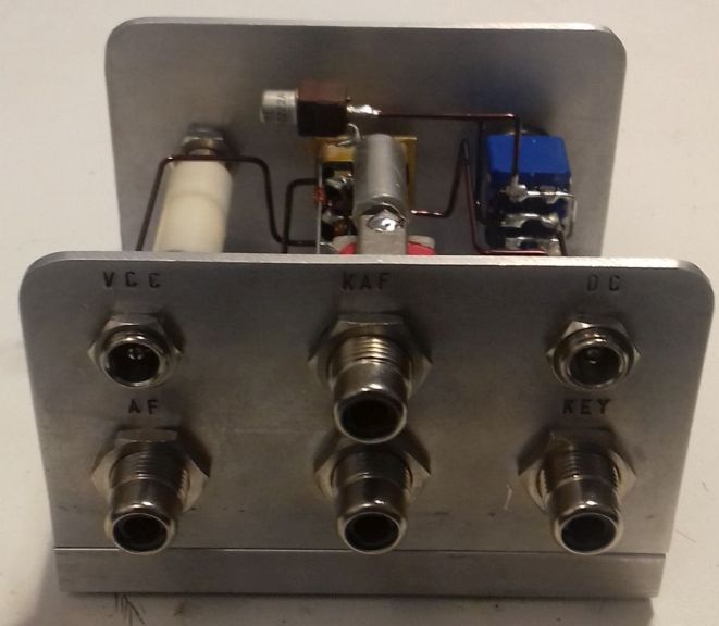
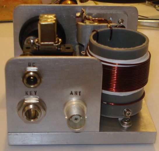
Back connections to the EMTX.
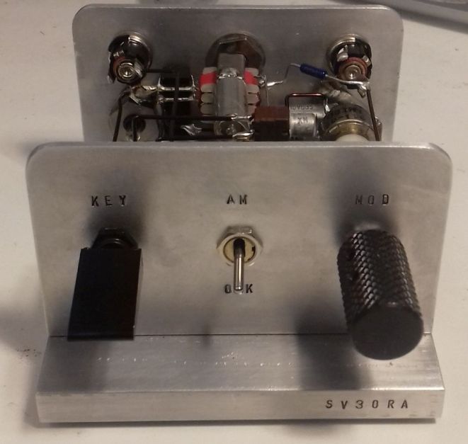
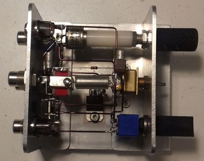
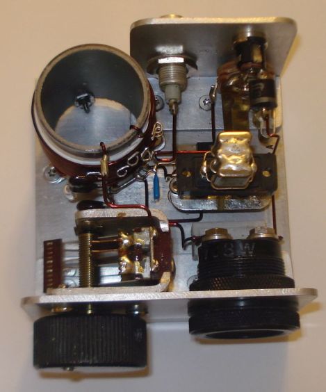
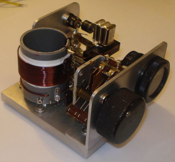
Pictures of the finished keyer/modulator. You don’t have to build it that nice-looking if you don’t care.
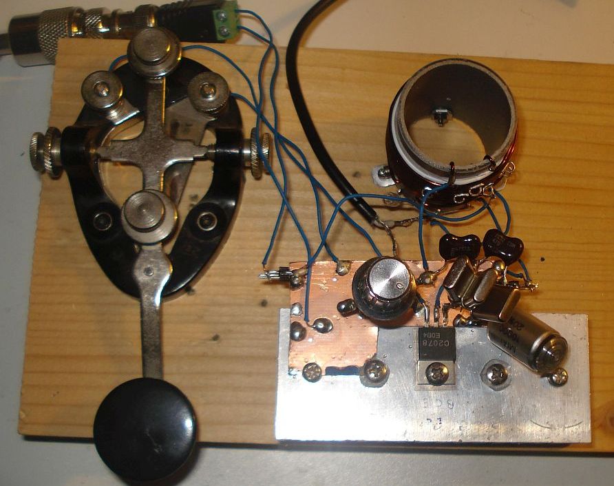
Modulator prototype and EMTX built on a breadboard. Yes it worked just fine onto a piece of wood.
Thank you so much for sharing this brilliant and simple project with us, Kostas. Your handiwork is absolutely brilliant too!
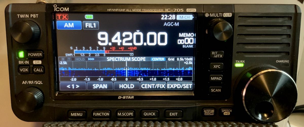
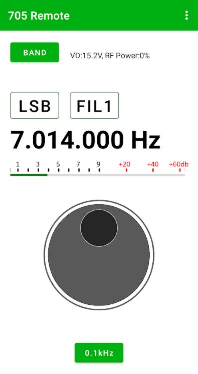
Many thanks to SWLing Post contributor, Markku Koskinen, who notes the following new and updated programs for the Icom IC-705 general coverage transceiver:
The app appears to control basic functionality like tuning, band, mode, filter, and CI-V address switching. The app is free and should work on most Android devices.
Many thanks to SWLing Post contributor, Kostas (SV3ORA), for sharing the following guest post which originally appeared on his radio website:
Emergency transmitter: An 8-component, high-power 40m/30m transmitter to get you quickly on the air
by Kostas (SV3ORA)
Introduction
QRP is all about doing more with less. This is more than true, with the construction of this cheap, simplistic transmitter presented here. It is designed primarily as an emergency transmitter (EMTX) that can be built or serviced in the field or at any home. However, it can be used as a HAM radio transmitter as well. Do not judge by its low components count though. This transmitter is powerful, more powerful than anything the QRPers would dream of. It is just remarkable how 8 components can lead in so much output power, that lets you communicate with a big part of the world, when propagation conditions are right. It is very difficult for a circuit to match that kind of simplicity in balance with such performance.
Following my detailed instructions, the EMTX can be reproduced easily, within hours. The result is always success, this is one of the circuits that are not critical at all and a successfully working transmitter can be reproduced every time. I have built this transmitter several times, using similar components (even toroids) and it always worked. The transmitter meets the next expectations:
1. Output power (including harmonics): A few mW up to 15W (depended on transistor, crystals and voltage/current used) at 50 ohm.
2. It can drive any antenna directly, 50 ohm or higher impedance, without external tuners.
3. Bands of operation: Currently 40m, 30m
4. Mode: CW, Feld-Hell (with external switching circuit), TAP code and any other ON/OFF keying mode. AM modulation has been easily applied too.
5. Options like reverse polarity protection diode (useful in the field when testing different unknown polarities PSUs) and current meter (for easier tuning) are available.
The challenge
The purpose of this transmitter is to be used primarily as an emergency transmitter. This poses several challenges that influence the design of the transmitter:
1. It must be able to be built or serviced easily in the field or at any home, with components that could be salvaged from near by electronics sources or a small electronics junk box. This means that components count should be kept very low and they must not be rare to find but commonly available parts. As a side effect cost would also be kept small, if one is to buy any component. Also, the active components must be interchangable with many other devices without the need for the design or the rest of the circuit components to be changed.
2. It must be able to operate from a very wide range of DC voltage sources and at relatively low current, so that common house power supplies could be used to supply power to it. Such devices include linear or switched mode power supplies from laptop computers, routers, printers, cell phone chargers, Christmas lights or any other device one might have available.
3. It must be capable of transmitting a powerful signal, so that communication is ensured. An emergency transmitter that is capable of a few mW of output power, might be heard locally (still useful, but there are handheld devices for that already) but isn’t going to be of much usage if it can’t be heard really far away.
4. It must be capable of loading any antenna without external equipment required. In an emergency situation, you just don’t have the luxury of building nice antennas or carrying coaxial cables and tuners. There may be even extreme cases where you can’t even carry a wire antenna and you depend on salvaging wire from sources in the field to put out a quick and dirty random wire antenna.
5. Adjustments of the transmitter should be kept minimum without the help of any external equipment and there must be indication of the correct operation of the transmitter or the antenna in the field.
Components selection
The transistor:
This transmitter has been designed so that it can operate with any NPN BJT in place. This includes small signal RF and audio transistors and high power RF transistors like the ones used on HF amplifiers and CB radios. Despite 2sc2078 is shown in the schematic, just try any NPN BJT in place and adjust the variable capacitor accordingly. When you are in the field, you do not have the luxury of finding special types of transistors. The transmitter must operate with any transistor in hand, or salvaged from near-by equipment. Of course the power capability of the transistor (as well as the crystal current handling) will determine the maximum VCC and current that can be applied to it and hence the maximum output power of the transmitter. Some of the most powerful transistors I have used, come out of old CB radios, such as the 2sc2078, 2sc2166, 2sc1971, 2sc3133, 2sc1969 and 2sc2312. There are many others. As an example, the 2sc2078 with a 20v laptop PSU, gave 10-12W of maximum output power into a 50 ohms load.
Schematic of the 8 components EMTX for the 40m/30m bands. Components with gray color are optional.
The crystal:
This is the most uncommon part of the transmitter. You have to find the crystal for the frequency that you want to operate on. Crystals within the 40m or 30m CW segments are not that common. Further more if you operate the transmitter at high powers and currents, you will notice crystal heating and chirp on the frequency of the transmitter. The current handling capability of your crystal die inside the crystal case, will determine the chirp and the amount of crystal heating. You can still work stations with a chirpy transmitter provided that the chirp is not that high, so that it can pass through the CW filters of the receivers. However, if a small chirp annoys you or if this chirp is too much, then you have to use these vintage bigger size crystals (e.g. FT-243), that can handle more current through them. But these are even more uncommon today.
The approach I have used in my prototype, was to connect more than one HC-49U crystals of the same frequency in parallel, so that the current is shared among them. This reduced the chirp at almost unnoticeable levels, even at high output power, just if I was using a single FT-243 crystal, or even better in some cases. Again, this is optional, but if you want to minimize chirp (and crystal heating) without searching for rare vintage crystals, this is the way to go.
A bit of warning. If you notice a very high chirp when plugging in a crystal to the EMTX, you should consider this crystal as inappropriate for this transmitter, as it cannot handle the current required. If you continue to use this inappropriate crystal, you could easily crack it inside and set it useless. Don’t use these tiny HC-49S crystals, they won’t work.
The current meter:
A 1Amp (or even larger) current meter can be used to monitor the current drawn by the transmitter during key down. The recommended current operating point is anywhere between 450mA to 1A, depended on the output power (and harmonics) level you want to achieve. The current point is set by the variable capacitor. I would avoid setting the current to more than 1Amp, although it can be done. The use of the current meter is optional, but along with the incandescent bulb, will give you a nice indication of the correct tuning of the transmitter, so that you do not need to have an external RF power meter connected to the transmitter output. If you do have, then you can remove the current meter. If you don’t have a 1Amp analogue meter available, but a smaller one, you can parallel a low value power resistor across the meter. In my case, I only had a 100uA meter and I paralleled a 0.15 ohms 5W resistor across it to scale down 1Amp to 100uA, The resistor value depends on the internal meter resistance so you have to calculate this for your specific meter. When the 2sc2078 is used at 20V, 500mA in the current meter indicates around 5W of output power, 600mA indicates around 6W, 700mA 7W, 800mA 8W, 900mA 9W and 1A around 10W. So the current meter can be used as sort of power meter without the need to do any scaling on it.
The incandescent bulb:
A current meter alone, without the use of the incandescent bulb, will not give you the right indication of the operation of the transmitter. In some cases, the transmitter might be drawing current without actually generating much, or even any RF. When you are in the field you do not want to carry extra monitoring equipment with you. The incandescent bulb will light on when the transmitter oscillates. It monitors the actual RF signal, so it’s brightness changes according to the amount of RF power the transmitter produces. Along with the current meter reading, this is just what you need to know in order to set the variable capacitor properly. Note that the bulb will not lit at very low signal levels. The one used in the prototype starts to glow up from a bit less than 1W. Miniature incandescent bulbs may not be that easy to find nowadays. However, there is a good source of these, that almost anyone has in their houses. This source is the old Christmas lights. You do save old Christmas lights, don’t you? The incandescent bulb indicator as well as it’s single turn winding on the transformer, are optional components. If you have an RF power meter connected to the transmitter, you can remove these.
The diode:
The protection diode is an optional component to the circuit. If you are in the field, correct polarity of a power supply may not be obvious. Without a multimeter it might me difficult to determine the correct polarity of the PSU. A power diode (I used a 6A one) will protect the transistor from blowing up in the event that reverse polarity is connected to the circuit.
The Cx and Cy:
The Cx and especially the Cy capacitors need to be of good quality. The Cy will get hot on high output power if it isn’t. In the tests, I have used homemade gimmick capacitor and even double-sided PCB as a capacitor for Cy and they all got hot at high power. Silver mica capacitors run much cooler and they do make a small difference in the output power, so I suggest to this type. Cy must be able to handle quite a lot of voltage, so silver mica type is ideal.
The variable capacitor:
The variable capacitor can be air variable or ceramic, although I prefer air variables in tis application. In any case it must be able to handle a high voltage just as the Cy.
The key:
The key directly shorts the transistor emitter to the ground, therefore it is a part of the active circuit. For this reason, I suggest the key leads to be kept as short as possible. The key must be able to handle the voltage (20v) and current (up to 1A) on its contacts, which is usually not a big deal.
Transformer construction
The construction of the transformer is shown below step by step. Note that if you decide that you don’t need to drive higher impedance loads but just 50 ohm ones (eg. antenna tuners or 50 ohm matched antennas), you just need to wind 2t in the secondary and not 14t. You also don’t need any taps of course.
Step 1:
Take a piece of 32mm external diameter PVC pipe from a plumber’s shop. Alternatively, a suitable diameter pills box can be used, or any other suitable diameter plastic tube.
Step 2:
Cut a 4cm piece out of this tube. 4cm is the minimum length required.
Below a 4cm PVC tube has been cut in size.
Step 3:
Wind 16 turns of 1mm diameter enameled wire onto the PVC pipe and secure the winding in place as shown in the picture below. Notice the winding direction of the wire. This is the primary of the transformer, the one that is connected to the two capacitors. Notice that this winding is wound a bit offset to the right of the pipe.
Step 4:
Wrap the winding with 3 turns of PTFE tape. It can be bought at any plumber’s shop, just like the PVC pipe. The PTFE tape will help in keeping the second layer turns in place and it will provide extra insulation.
Step 5:
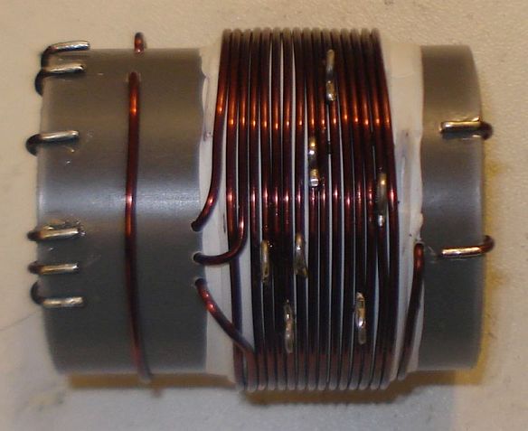
Wind 2 turns of 1mm diameter enameled wire on top of the primary winding and secure the winding in place as shown in the picture below. Notice the winding direction of the wire, as well as it’s position relative to the primary winding. This is the feedback of the transformer, the one that is connected to the collector of the transistor.
Step 6:
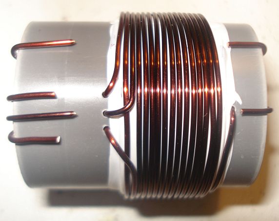
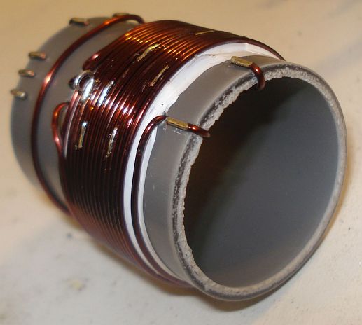
Wind 14 turns of 1mm diameter enameled wire on top of the primary winding, starting from just next to the 2 turns one and secure this winding in place as shown in the picture below. Notice the winding direction of the wire, as well as its position relative to the primary and the 2 turns windings. This is the secondary (output) of the transformer, the one that is connected to the antenna. At this point do not worry about the taps yet.
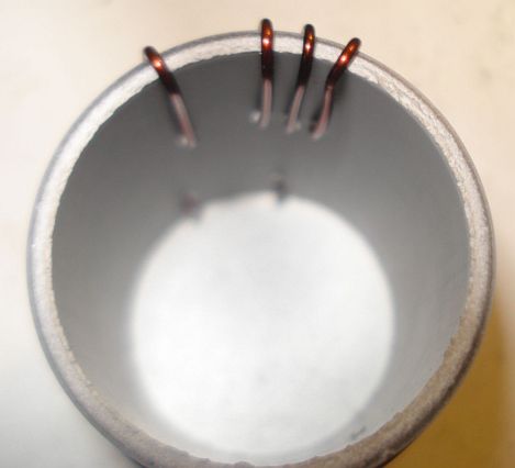
Notice in the picture below, the way the windings are secured in place onto the pipe. The wire ends are passed through the pipe using small holes and then bent towards the ends of the pipe and once more to the surface of the pipe, where the connections will be made.
Step 7:
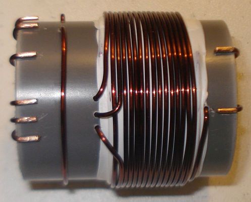
Wind 1 turn of 1mm diameter enameled wire onto the pipe and secure the winding in place as shown in the picture below. Notice the winding position relative to the other windings. This 1 turn winding is placed about 1cm away from the other windings. This is the RF pick up winding, the one that is connected to the incandescent bulb.
Step 8:
Use a sharp cutter (knife) and carefully scrap the enamel of all the windings ends. Do not worry if you cannot scrap the enamel at the bottom side of the wire ends (that touches to the pipe). We just want enough copper exposed to make the connection.
Step 9:
Tin the scrapped wire ends, taking care not to overheat them much.
Step 10:
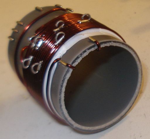
Now it’s time to make the taps on the secondary winding. Use a sharp cutter (knife) and very carefully scrap the enamel of the wire at the tap points (number of turns). Take much care not to scrap the enamel of the previous and the next turn from each tap point. Do not worry if you just scrap the enamel at the top of the wire (external area). We just want enough copper exposed to make the connection.
Make each tap, a bit offset from the near by taps, like shown in the pictures. This will avoid any short circuits (especially at the 4, 5 and 6 taps) and it will allow for easier connections, especially if alligator clips are used to connect to the taps.
Step 11:
Tin all the tap points, taking care not to overheat them.
Step 12:
This step is optional and it depends on how you decide to do the connections to the taps. You may solder wires directly to the tap points, but in my case I wanted to use alligator clips, so I did the next: I took a piece of a component lead and soldered it’s one end to each tap point. Then I bent the component lead to U-shape and cut it accordingly. This created nice and rigid tap points for the alligator clip.
Step 13:
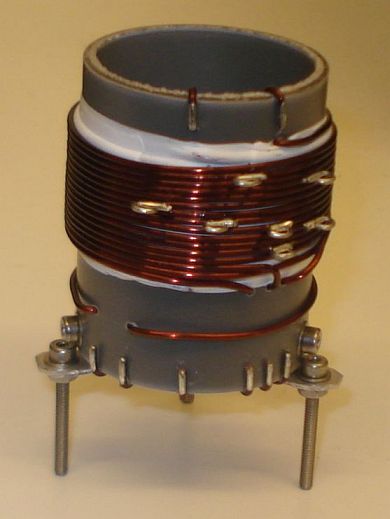
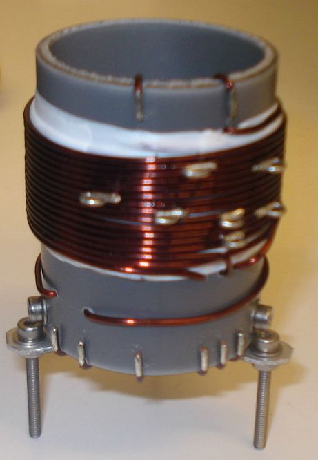
This step is optional and it depends on how you decide to mount the transformer to your enclosure. In my case, I wanted to create three small legs for the mounting. I cut three pieces of aluminum straps and made holes at both their ends. I made three small holes onto the transformer pipe end and mounted the aluminum straps using screws. After mounting them, I shaped the straps to L-shape. Then I used three more screws to mount the transformer to the enclosure.
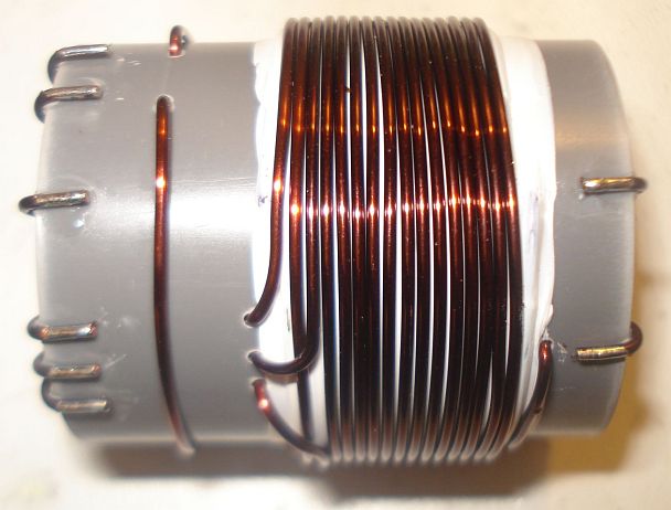
The completed transformer is shown in the pictures above and below. The 6 connection points at the bottom of the pipe, are the low voltage points, whereas the 2 points at the top of the pipe, are the high voltage points.
If you have built the transformer as described, the bottom connections are as follows (from left to right):
Wire end 1, connected to the incandescent bulb
Wire end 2, connected to the incandescent bulb
Wire end 3, connected to the current meter
Wire end 4, connected to the current meter
Wire end 5, connected to the GND (ground)
Wire end 6, connected to the transistor collector
The top connections are as follows (from left to right):
Wire end 1, connected to the 25pF variable capacitor and the Cy fixed.
Wire end 2, is the 14th secondary tap and it is left unconnected, or tapped to the appropriate impedance antenna.
Videos of the EMTX in operation
I have made two small videos of the EMTX in operation.
The first 13.5MB video (right click to download), shows the operation when the transmitter is set for a bit less than 10W of output power.
The second 3.5MB video (right click to download), shows the operation when the transmitter is set for about 5W of output power.
EMTX chirp analysis
Every self-exited power oscillator (and even many multi-stage designs) exhibits some amount of chirp. Chirp is mainly considered as the sudden change in frequency when the power oscillator is keyed down. Apart from chirp, there is also the longer term frequency stability that may be considered. The chirp in the EMTX is surprisingly low, if it is built properly. Hans Summers, G0UPL has performed a chirp analysis on my EMTX (PDF) and the EMTX built by VK3YE and presented on YouTube. Hans, performed the analysis from the video/audio recordings of both transmitters. I sent him two videos, one with the EMTX set for an output power of 10W and one where it is set for 5W. The chirp at worst case (10W) was about 30Hz and at 5W in the order of 10Hz or so. Being so small, the chirp is almost undetectable by the ear and it surely poses no problems when passing the tone through narrow CW filters. This is an amazing accomplishment from a transmitter so simple and so powerful.
EMTX harmonics measurement
Every unfiltered transmitter will excibit harmonics at it’s output. This means that the output waveform has some distortion in comparison to a pure sinewave. Many of the transmitters I have seen, present a very distorted output waveform and absolutely need a LPF if they are to be connected to an antenna. I can’t say that this is true for the EMTX, because surprizingly, it has low distordion, despite the high output power it can achieve. Although a LPF is always a good idea, it is not that much needed on the EMTX. However you have to use one to comply with the regulations.
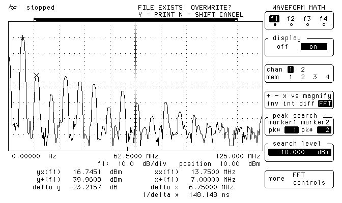
The image above, shows the measurements on the output of the EMTX, when it is set closely to 10W at 50 ohms. The main carrier is exactly at 9.9W and all the harmonics are less than 50mW! Also, the harmonics, do not extend into the VHF region.
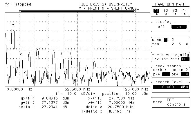
The image below, shows the measurements on the output of the EMTX, when it is set closely to 5W at 50 ohms. The main carrier is exactly at 5.17W and all the harmonics are less than 9.6mW! Again, the harmonics, do not extend into the VHF region.
These small harmonics levels aren’t going to be heard very far at all, compared to the powerful carrier. This means only one thing. A LPF, although a good practice, is not mandatory in this transmitter. But you should better use one so that you comply with the regulations.
Many HAMs use just a watt meter to measure the output of their homebrew transmitters. This is not the proper way of doing it, because the watt meter is a non-selective meter. It will measure both the fundamental carrier and the harmonics, without being able to distinguish them. So in an unfiltered transmitter, or in a transmitter with a simple (often non measured) LPF, this way will give a totally false reading of the output power of the transmitter at the set frequency.
The proper way of accurately measuring the output power of a transmitter and the harmonics levels, is a spectrum analyzer. The FFT available in many modern oscilloscopes, having a dynamic range of approximately 50-55dB, is adequate for this purpose as well. A 50 ohms dummy load must be connected at the transmitter output and then the high impedance probe of the scope, is connected to the output of the transmitter as well. This was the way that the above measurements have been performed.
WebSDR tests
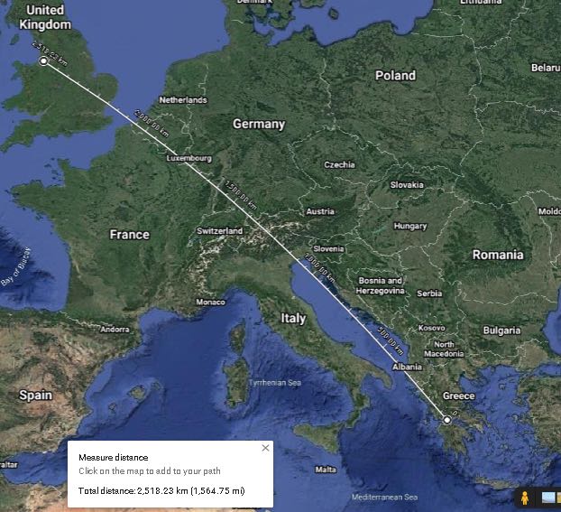
Here are some test transmissions, to determine how far one can get with such a transmitter. I have to say that there is an antenna tuner between the EMTX and my inefficient short dipole (not cut for 40m and not even matched to the coaxial). However I could still cover a distance of more than 2500Km even on the 5W setting.
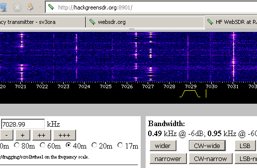
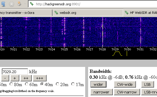
A screenshot of the transmitter signal, as received on a WebSDR 2500Km away and when the EMTX is set for an output power of 10W.
Below, is a picture and an audio recording of the transmitter signal, as received on the same WebSDR and when the EMTX is set for an output power of 5W.
Photos
Pictures of the finished transmitter. You don’t have to build it that nice-looking if you don’t care.
EMTX prototype built on a breadboard. Yes it worked just fine onto a piece of wood.
This is a phenomenal project, Kostas. Thank you so much for sharing it with us. I love the simplicity of this design–truly form following function. With a little patience, anyone could build this transmitter.
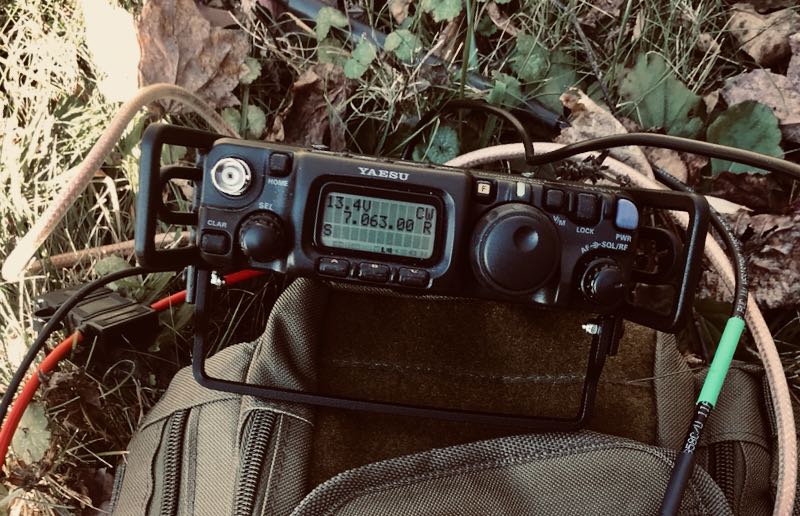
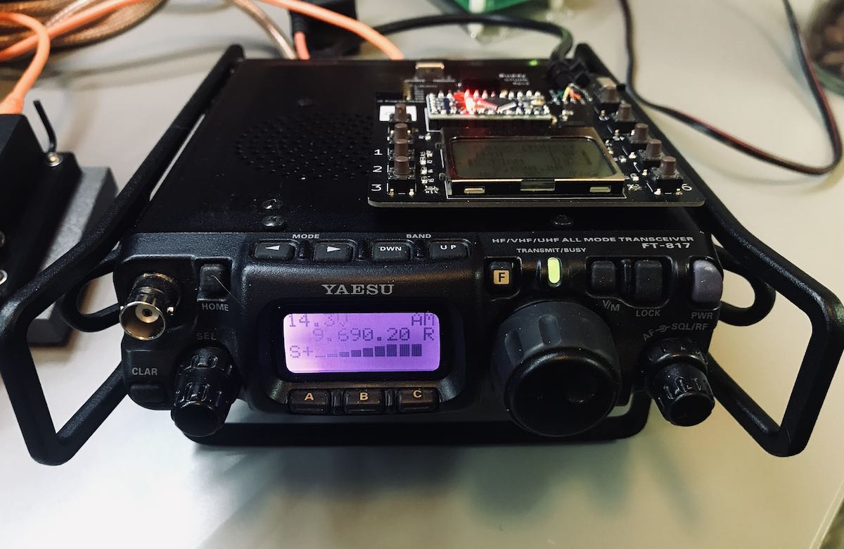
Andy’s article caused me (yes, I blame him) to wax nostalgic about the popular FT-817 transceiver. You see, I owned one of the first production models of the FT-817 in 2001 when I lived in the UK.
At the time, there was nothing like it on the market: a very portable and efficient HF, VHF, UHF, multi-mode general coverage QRP transceiver…all for $670 US.
In 2001? Yeah, Yaesu knocked it out of the ballpark!
In fact, they knocked it out of the ballpark so hard, the radio is still in production two decades later and in demand under the model FT-818.
I sold my FT-817 in 2008 to raise funds for the purchase of an Elecraft KX1, if memory serves. My reasoning? The one thing I disliked about my FT-817 was its tiny front-facing display. When combined with the embedded menus and lack of controls, it could get frustrating at home and in the field.
I mentioned in a previous post that I purchased a used FT-817ND from my buddy, Don, in October, 2020. I do blame Andy for this purchase. Indeed, I hereby declare him an FT-817 enabler!
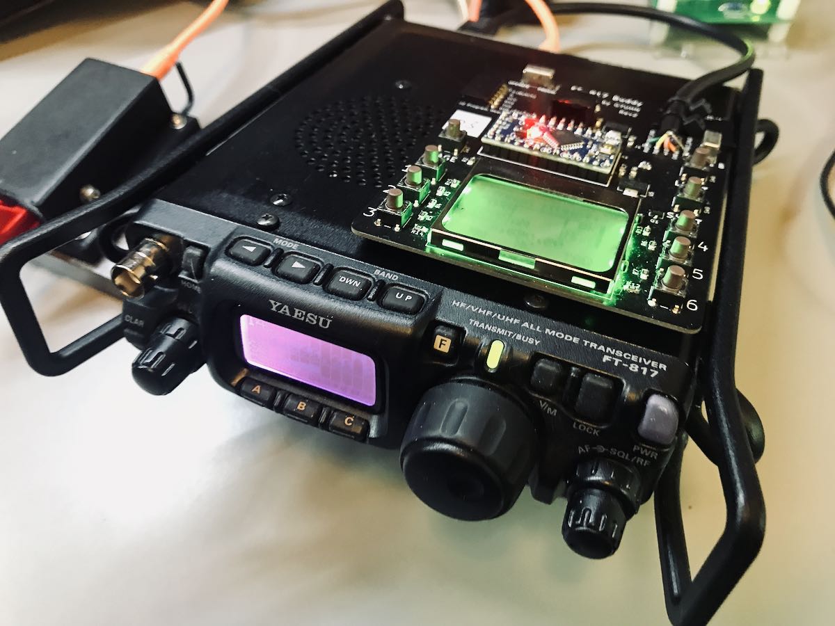
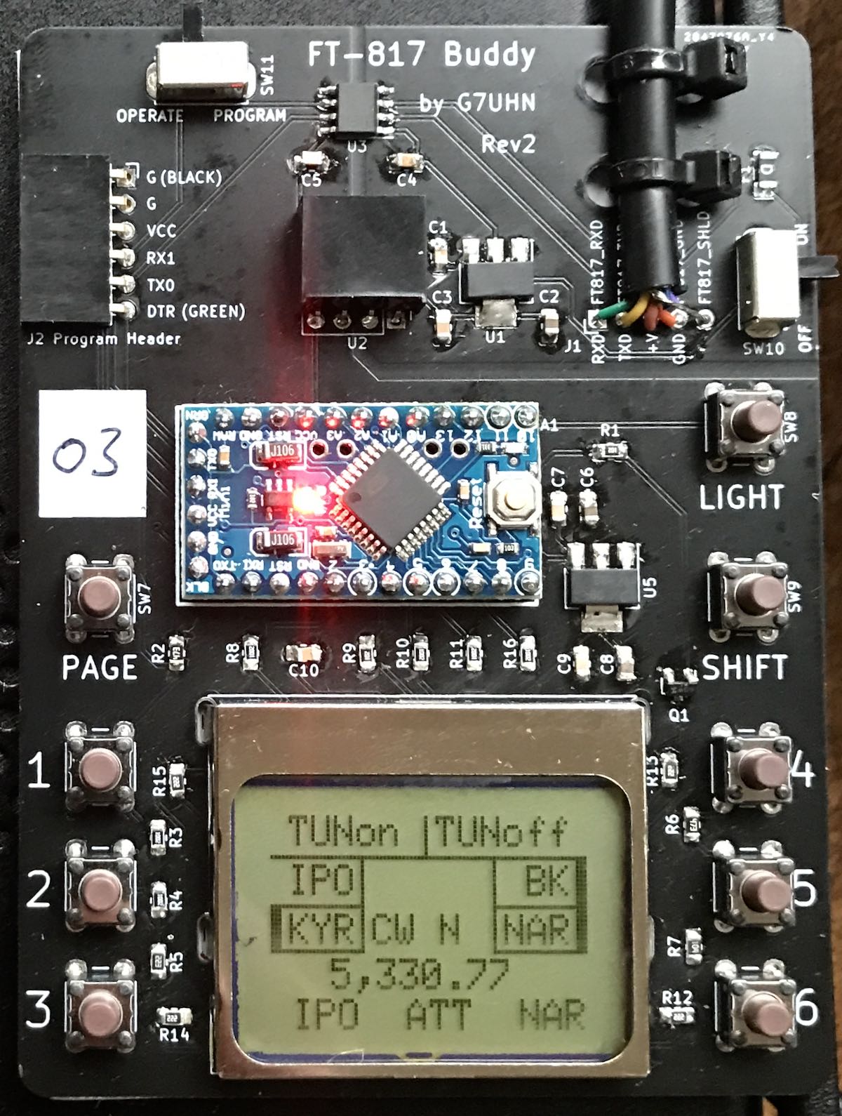
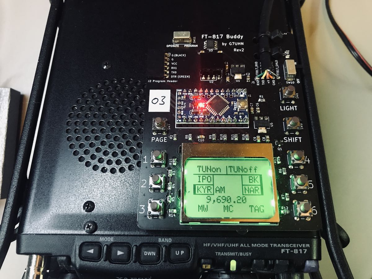
FT-817 Buddy board
When I told Andy about my ‘817ND purchase, he asked if I’d like to help him test the FT-817 Buddy board versions. How could I refuse?
Andy sent me a prototype of his Version 2 Buddy board which arrived in late November. I had to source out a few bits (an Arduino board, Nokia display, and multi-conductor CAT cable). Andy kindly pre-populated all of the SMD components so I only needed to solder the Arduino board and configure/solder the cable. I did take a lot of care preparing and soldering the cable, making sure there was no unintentional short between the voltage and ground conductors.
Overall, I found the construction and programming pretty straight-forward. It helped that Andy did a remote session with me during the programming process (thanks, OM!). Andy is doing an amazing job with the documentation.
I do love how the board makes it easier to read the frequency and have direct access to important functions without digging through embedded menus. While there’s nothing stopping you from changing the program to suit you, Andy’s done a brilliant job with this since he’s an experienced FT-817 user.
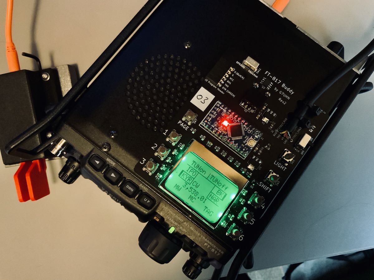
The Nokia display is very well backlit, high contrast, and easy very to read.
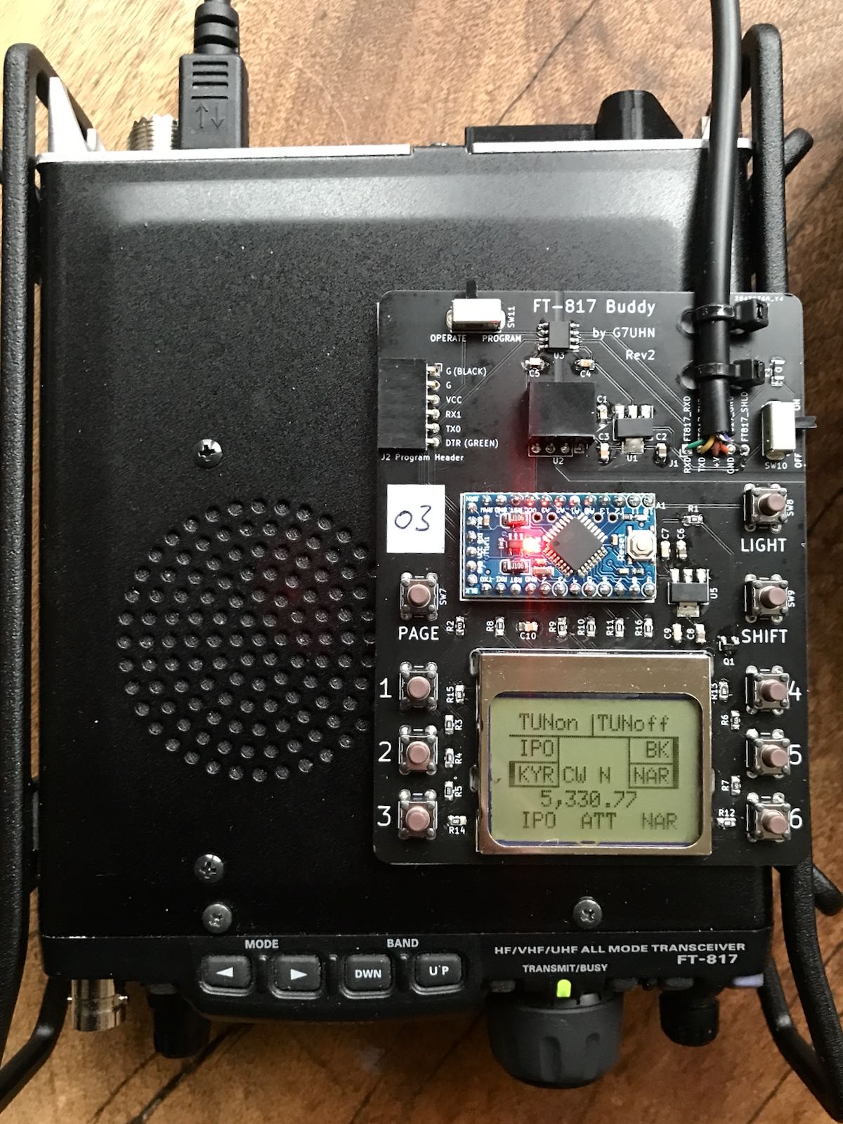
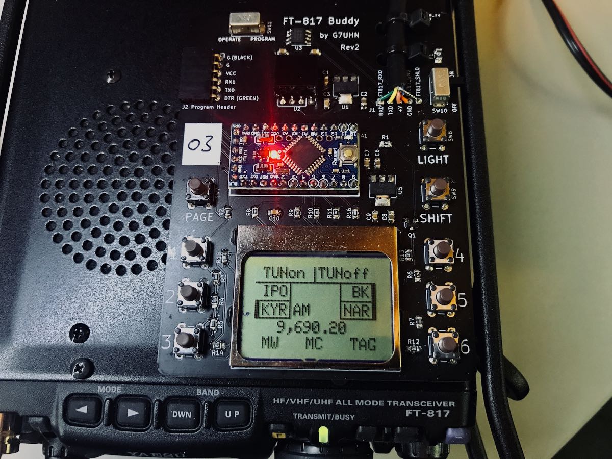
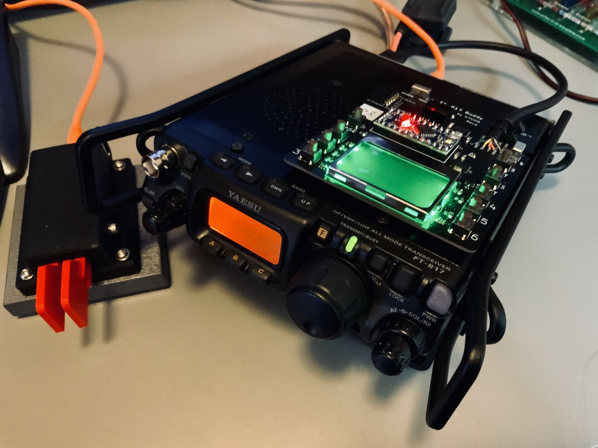
“Resistance is futile”
I mentioned on Twitter that, with the backlight on, the FT-817 Buddy makes my ‘817ND look like it was recently assimilated by The Borg.
Don’t tell any Star Trek captains, but I’m good with that.
Andy has a rev3 board in the works and it sports something that will be a game-changer for me in the field: K1EL’s keyer chip!
For more information about the FT-817 Buddy, check out Andy’s website. At time of posting, it’s not available yet, but as Andy says, “it’s nearly there!”
Of course, we’ll keep you updated here as well. Many thanks to Andy for taking this project to the next level. No doubt a lot of FT-817 users will benefit from this brilliant project!
This morning, I’m catching up with email and posts as I’ve had less online time these past few days (not a bad thing). I’m also trying to sort out and organize some of the gear in my compact shack/office.
As I do this, I can’t help but think through some of the radio projects that await me in 2021–so I started making a list.
2021 Radio Goals
Portable DXing: I hope I’ll be able to travel again in the latter part of 2021 and take my portable SDR pack to capture spectrum recordings in the field. I really miss doing this.
Carefully go through my portable radio collection and “thin the herd.” I’ve no intention of letting go of everything, but I’ve a number of small, inexpensive portables I never touch and don’t plan to use for comparisons
Purchase a few more cables and a mic to complete my multitrack recording and receiver comparison setup. Massive thanks to my friend, Matt Blaze, who’s helped me through this process.
Finally replace that faulty keypad on the Drake SW8! (This might be the first thing I do in the new year.)
Antenna Farm improvements and upgrades:
It’s time for the remote tuner box to get a rennovation!
I plan to re-build my remote tuner box (that’s served me so well for a decade–see photo)
install all new connectors, components, and change the balun
add a remote antenna switching device
beef up lightening protection
and replace all of the coax feed lines.
I also plan to add a home brew 80 meter vertical and possibly a 20M delta loop oriented E/W
QRP EME: I still need to sort out a VHF amplifier, antenna, connectors and cables for my QRP EME station. I hope to have the pieces together by mid 2021.
Build my QCX+ and QCX Mini transceivers (really looking forward to that!)
In truth? I’ve more goals than this, but I’m trying to be somewhat realistic. The top priority is investing time in my antenna situation at home. All of the coax lines are aging and I know are no longer up to spec. I see cable and even connectors as long-term consumables and it’s definitely time to reinvest!
How about you? What are your radio goals for 2021?
Also been modding the FT-817ND with a Buddy Board prototype by Andy (G7UHN). Installing version 3 in a few weeks!
Please comment and let us know what you’re plotting and planning! Inquiring minds want to know!
Here’s wishing everyone a happy & healthy New Year!
Thank you for being a part of the SWLing Post community!
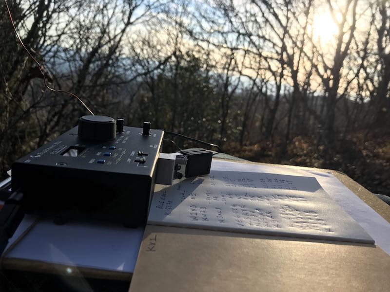
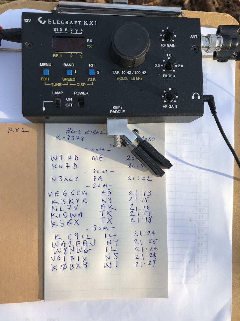
SWLing Post readers: I originally posted the following article on QRPer.com where I publish most of my ham radio field reports. It was the first full Parks On The Air activation with my recently re-acquired Elecraft KX1 transceiver and it was very memorable. I hope you enjoy:
Yesterday [Saturday, November 14, 2020] my family decided to make an impromptu trip to one of our favorite spots on the Blue Ridge Parkway at Richland Balsam–the highest point on the BRP.
Of course, it was a good opportunity to fit in a Parks On The Air (POTA) activation, but I had also hoped to activate Richland Balsam for Summits On The Air (SOTA) simultaneously.
It being well beyond leaf-looking season, we had hoped the BRP would be relatively quiet, but we were wrong.
Trail heads were absolutely jam-packed and overflowing with visitors and hikers. We’ve noticed a sharp hiker uptick this year in western North Carolina due in no small part to the Covid-19 pandemic. People see hiking as a safe “social-distance” activity outdoors, but ironically, hiker density on our single-track trails is just through the roof. One spends the bulk of a hike negotiating others on the trail.
The trail head to Richland Balsam was no exception. Typically, this time of year, we’d be the only people parked at the trail head but yesterday it was nearly parked full.
Being natives of western North Carolina, we know numerous side-trails and old logging/service roads along the parkway, so we picked one of our favorites very close to Richland Balsam.
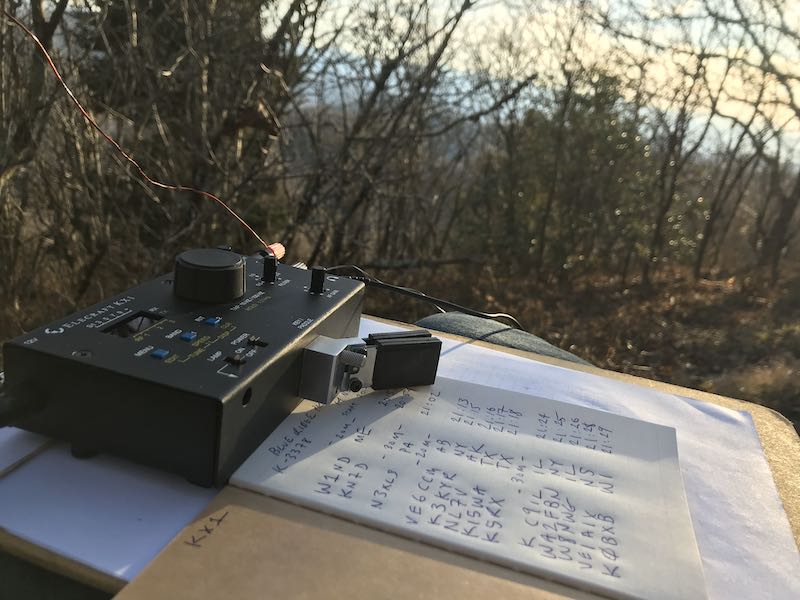
We hiked to the summit of a nearby ridge line and I set up my POTA station with the “assistance” of Hazel who always seems to know how to get entangled in my antenna wires.
“I’m a helper dog!”
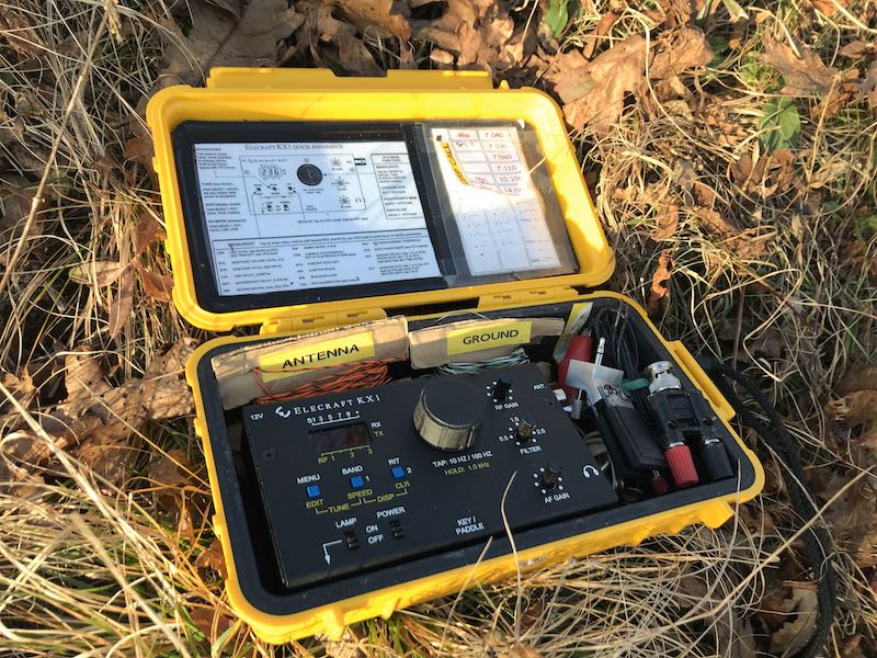
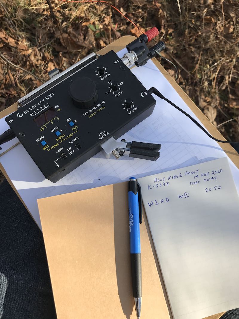
Taking a break from using the Icom IC-705, I brought my recently reacquired KX1 field radio kit.
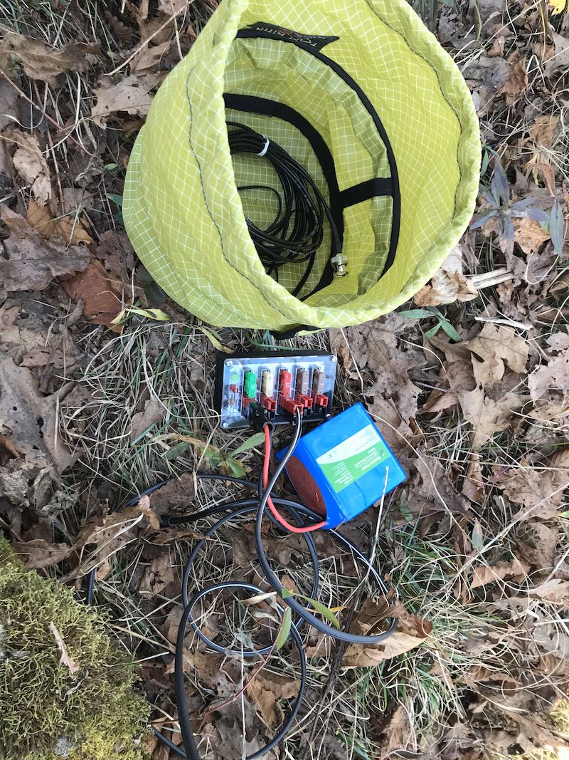
I carried a minimal amount of gear on this outing knowing that there would be hiking involved. Everything easily fit in my GoRuck Bullet Ruck backpack (including the large arborist throw line) with room to spare.
I took a bit of a risk on this activation: I put faith in the wire antenna lengths supplied with my new-to-me Elecraft KX1 travel kit. I did not cut these wires myself, rather, they are the lengths a previous owner cut, wound, and labeled for the kit.
With my previous KX1, I knew the ATU was pretty darn good at finding matches for 40, 30, and 20 meters on short lengths of wire, so I threw caution to the wind and didn’t pack an additional antenna option (although I could have hiked back to the car where I had the CHA MPAS Lite–but that would have cut too much time from the activation).
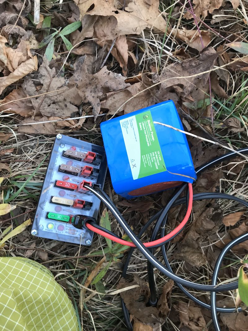
I didn’t use internal batteries in the KX1, rather, I opted for my Bioenno 6 aH LiFePo battery which could have easily powered the KX1 the entire day.
I deployed the antenna wire in a nearby (rather short) tree, laid the counterpoise on the ground, then tried tuning up on the 40 meter band.
No dice.
The ATU was able to achieve a 2.7:1 match, but I don’t like pushing QRP radios above a 2:1 match if I don’t have to. I felt the radiator wire was pretty short (although I’ve yet to measure it), so clipping it would only make it less resonant on 40 meters.
Instead, I moved up to the 20 meter band where I easily obtained a 1:1 match.
I started calling CQ POTA and within a couple of minutes snagged two stations–then things went quiet.
Since I was a bit pressed for time, I moved to the 30 meter band where, once again, I got a 1:1 match.
I quickly logged one more station (trusty N3XLS!) then nothing for 10 minutes.
Those minutes felt like an eternity since I really wanted to make this a quick activation. I knew, too, that propagation was fickle; my buddy Mike told me the Bz numbers had gone below negative two only an hour before the activation. I felt like being stuck on the higher bands would not be to my advantage.
Still, I moved back up to 20 meters and try calling again.
Then some radio magic happened…
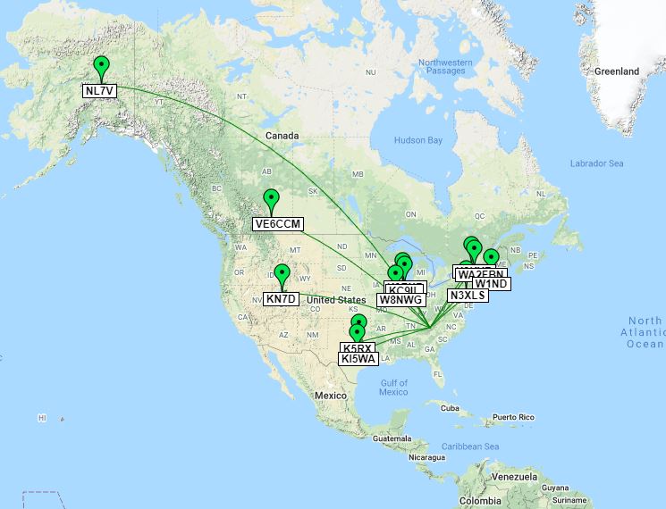
Somehow, a propagation path to the north west opened up and the first op to answer my call was VE6CCA in Alberta. That was surprising! Then I worked K3KYR in New York immediately after.
It was the next operator’s call that almost made me fall off my rock: NL7V in North Pole, Alaska.
In all of my years doing QRP field activations, I’ve never had the fortune of putting a station from Alaska in the logs. Alaska is a tough catch on the best of days here in North Carolina–it’s much easier for me to work stations further away in Europe than in AK.
Of all days, I would have never anticipated it happening during this particular activation as I was using the most simple, cheap antenna possible: two thin random lengths of (likely discarded) wire.
People ask why I love radio? “Exhibit A”, friends!
After working NL7V I had a nice bunch of POTA hunters call me. I logged them as quickly as I could.
I eventually moved back to 30 meters to see if I could collect a couple more stations and easily added five more. I made one final CQ POTA call and when there was no answer, I quickly sent QRT de K4SWL and turned off the radio.
I still can’t believe my three watts and a wire yielded a contact approximately 3,300 miles (5311 km) away as the crow flies.
This is what I love about field radio (and radio in general): although you do what you can to maximize the performance of your radio and your antenna, sometimes propagation gives you a boost when you least expect it. It’s this sense of wireless adventure and wonder that keeps me hooked!
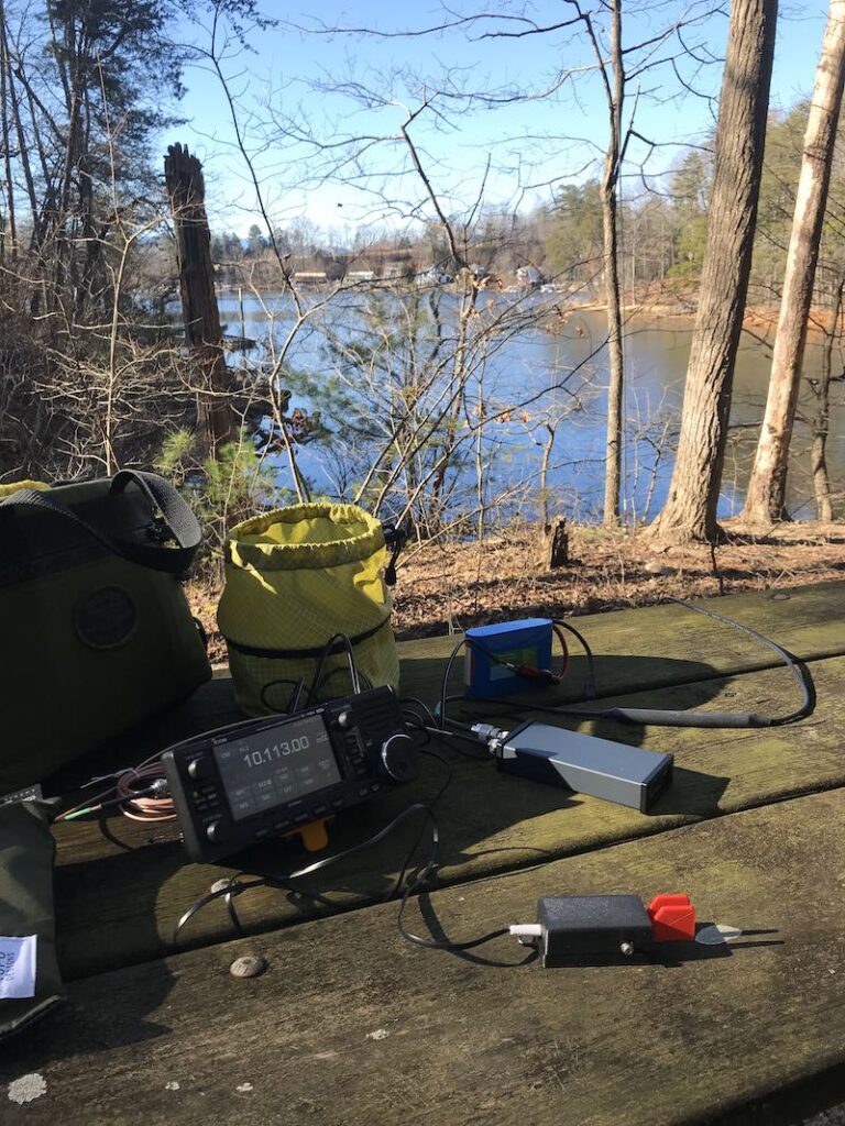
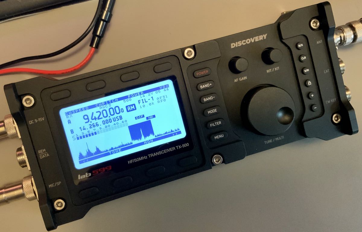
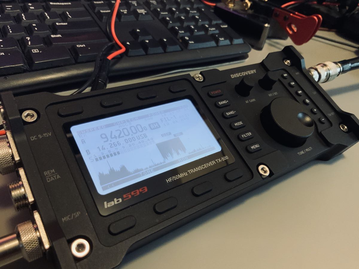
The following review of the TX-500 was first published in the October 2020 issue of The Spectrum Monitor magazine.
Last year, a company out of Russia started dropping hints about a QRP transceiver they were developing called the Discovery TX-500.
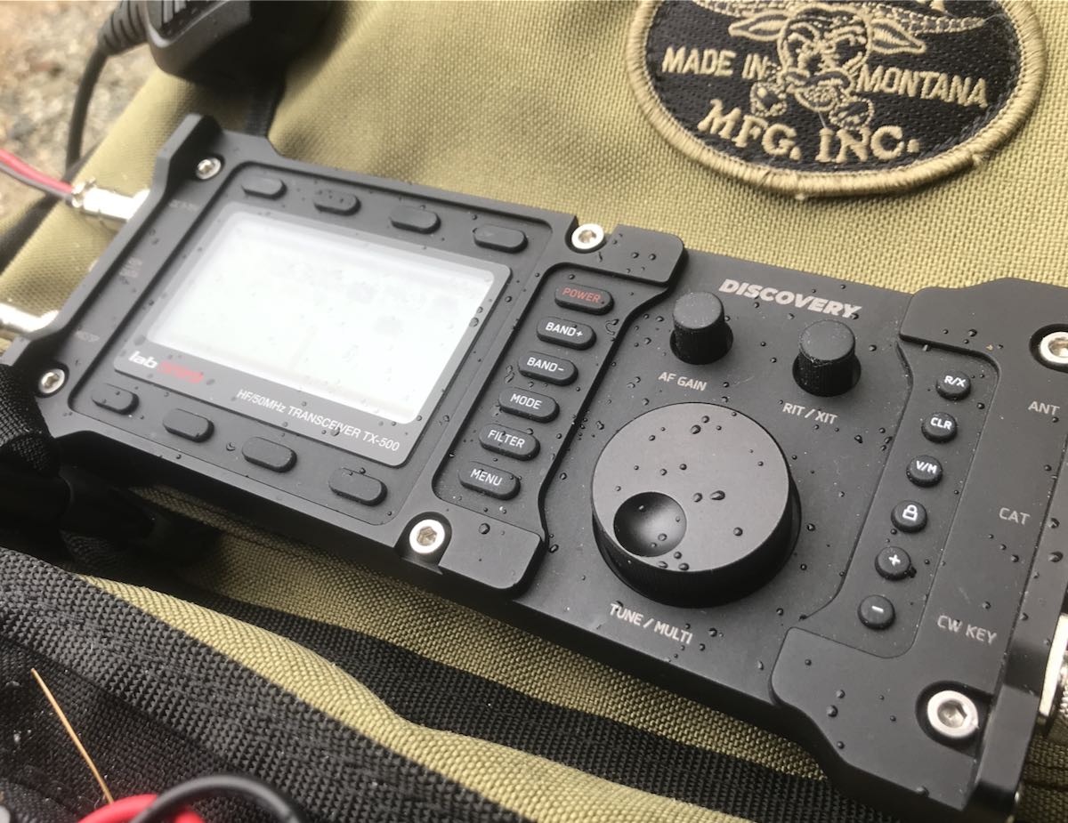
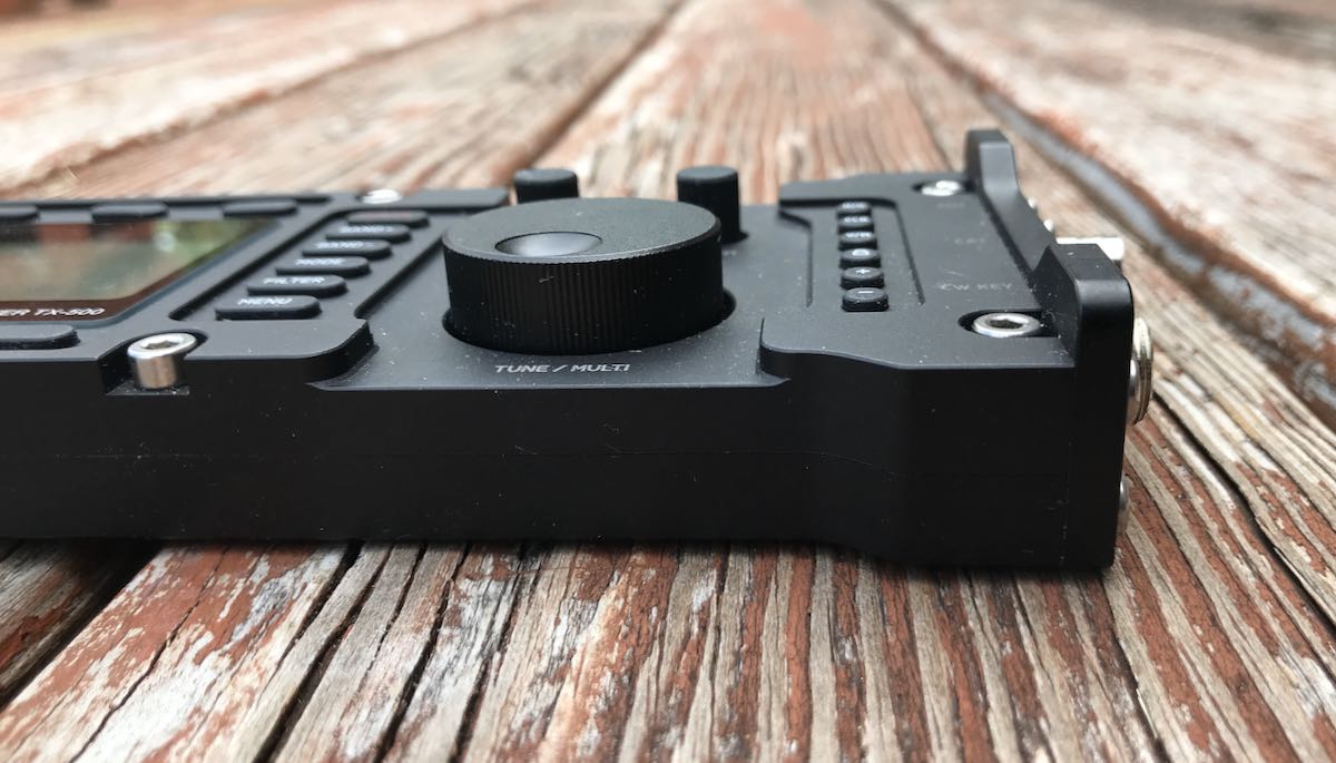
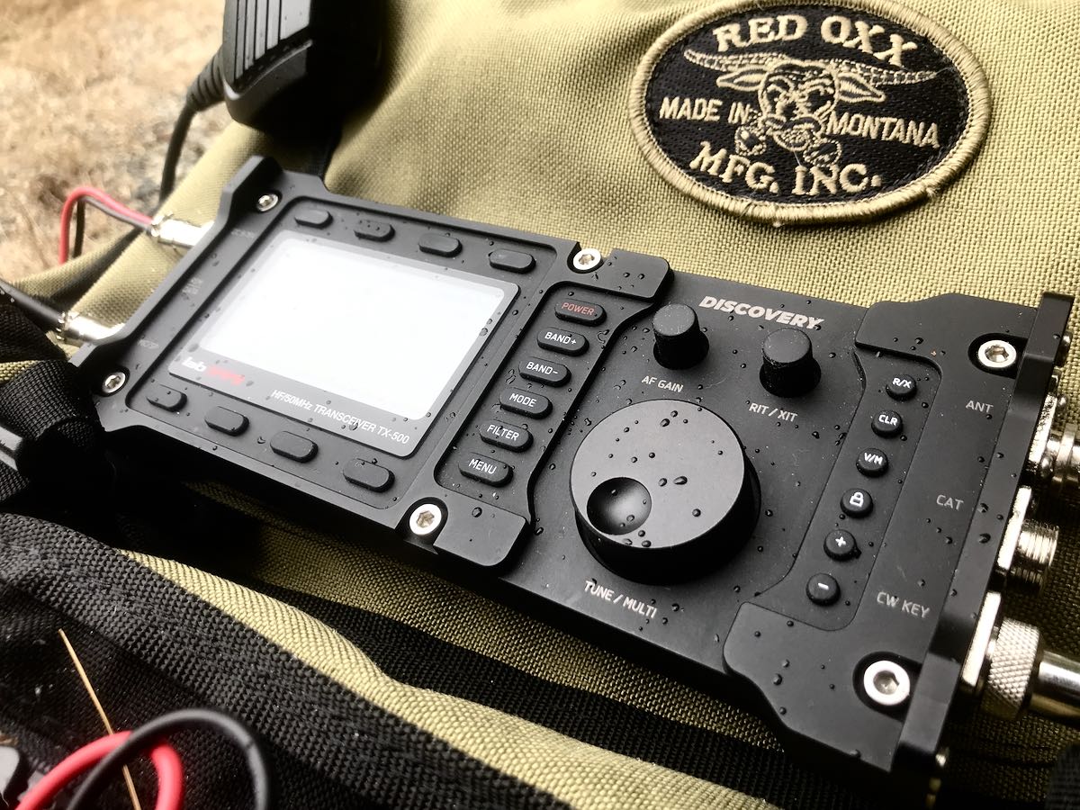
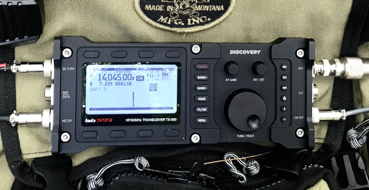
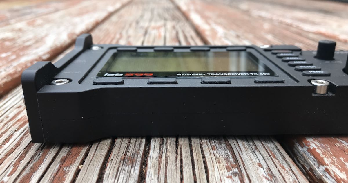
The prototype photos looked like nothing else on the market: it was unusually thin––only 30mm thick––and sported a CNC-machined aluminum alloy body. The radio also featured top-mounted controls ideal for field use, and a high-contrast LCD backlit screen with a spectrum display.
Some of the initial photos of the prototype showed water droplets on the front faceplate indicating that the TX-500 would be water/weather resistant––certainly a first for the amateur radio market.
After the initial hints dropped by lab599, the TX-500 developed somewhat of a cult following among field-portable radio operators (like yours truly) as well as those into radio preparedness. However, after this tantalizing flurry of initial images, there was a lull, and very little information was available about the rig. Then in late July/early August 2020, we finally learned that the TX-500 would be sold in the US by Ham Radio Outlet. HRO’s product page posted a price of $789.95 with a projected availability date of mid-to-late September 2020.
Thus I felt quite lucky when I learned that a loaner TX-500 was being sent to me for one week to evaluate and review. Those of you who know me and read my reviews know that I typically prefer to spend several weeks with a radio before I feel comfortable enough writing a review. In this case, that simply wasn’t an option. I decided to push aside all of my other obligations and simply dive into this radio.
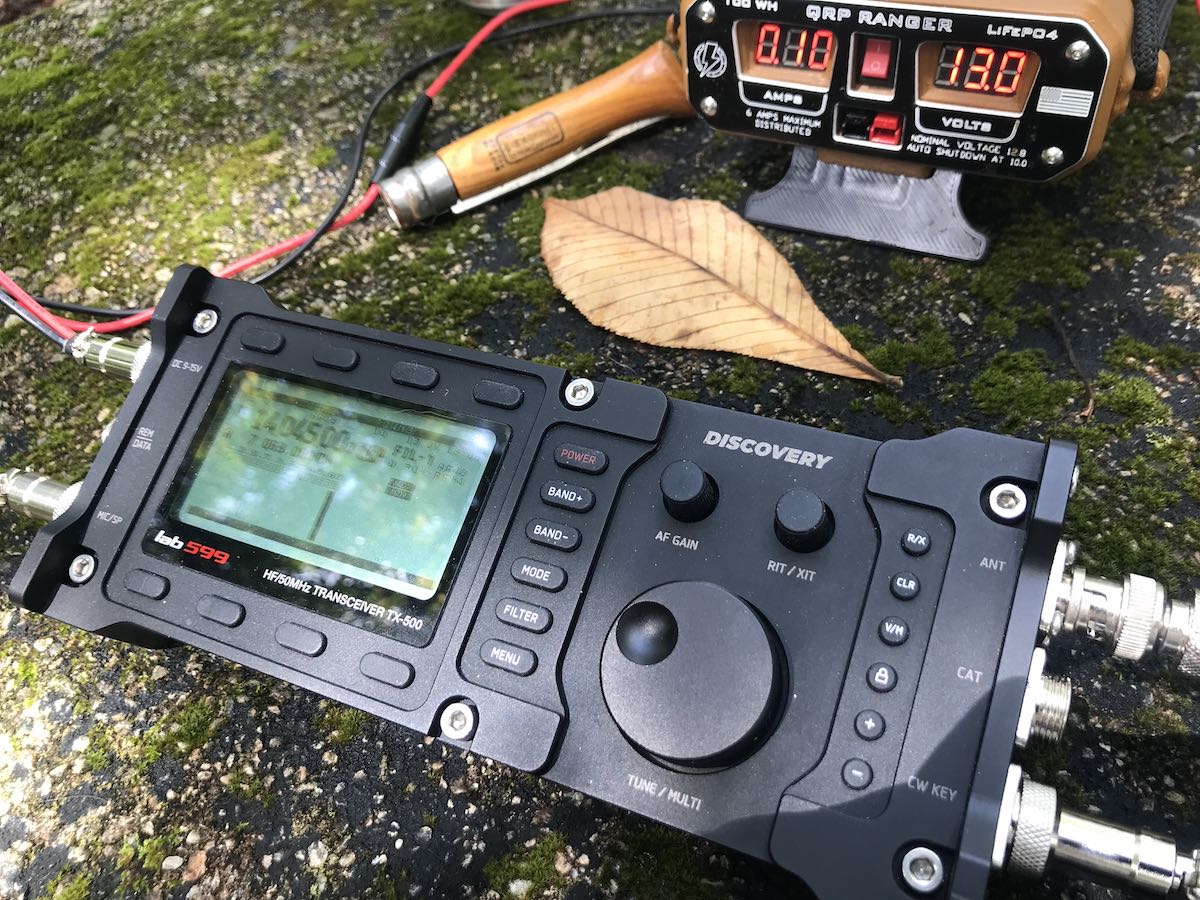
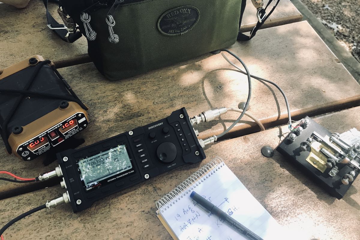
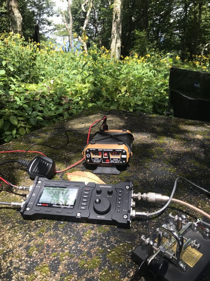
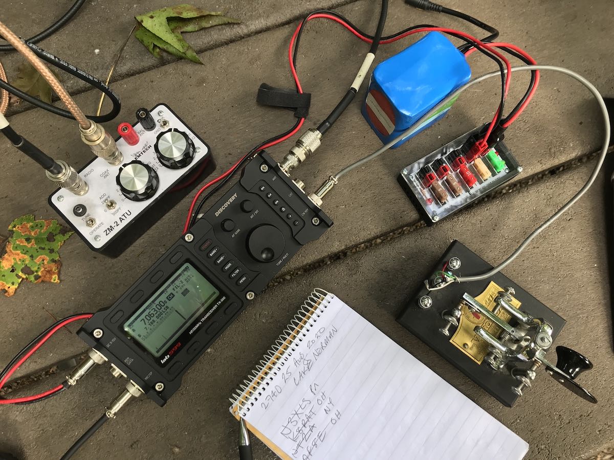
The following review is based on using the TX-500 in the shack and in the field over the course of seven days. During this week, I managed to activate eight parks for the Parks on the Air (POTA) program, exclusively with the TX-500. I’ve taken the TX-500 to state parks, lakes, game lands, a National Forest, and a National Park. The TX-500 experienced full-on sunshine during a long operating session, and was even rained on once.
I’ve also made a number of QSOs with this radio from home, both via CW and phone. In total, I’ve logged an average of 31 CW and SSB contacts with the TX-500 each day I’ve had it.
Initial impressions
The TX-500 looked so impressively machined and designed based on the initial photos and few videos published, I honestly feared it couldn’t possibly measure up to the expectations built up about it. Would it be the rugged radio we’d heard about? Could it travel? Could it hold up in the field, under variable conditions and in fickle weather?
With the radio finally in hand, I noted the build quality and thought to myself, This rig might just do it.
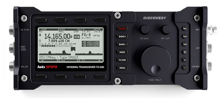
The body of this radio is absolutely solid. It’s weighty without being heavy, and there are no loose parts––no wobbly encoders, no wonky buttons, and relatively few seams or openings that might be subject to dust or water penetration. It’s rugged, sturdy––and, I must add––beautifully engineered.
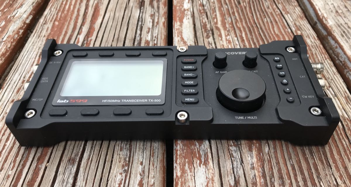
The layout is simple: there’s a backlit LCD screen on the left of the radio with four function buttons above and below it. These buttons control most of the functions and features you use while operating: CW adjustments, Receive and Transmit audio EQ, Noise Reduction, Noise Blanker, CW Memory keying, A/B VFO control, and more.
To the right of the display you find a set of buttons stacked vertically that include the power button, mode, band switching, and a menu button for making less common adjustments. The encoder is raised and feels silky-smooth to operate. There appears to be no brake control, but this is not a problem because this rig doesn’t need it: it’s well-balanced and feels of excellent quality. Indeed, tuning is adaptive and fluid; I’ve been very pleased with the lab599 tuning.
There are two knobs above the encoder which adjust the AF gain and RIT. Other buttons next to the encoder control things such as the tuning steps and speed, controls lock, and memory writing.
The low-profile side panels do protect the TX-500 front faceplate on flat surfaces.
You can tell the TX-500 was designed by an amateur radio operator because the radio is laid-out beautifully. All frequently used functions are easy to find and intuitive. There’s no need to do a deep-dive into embedded menus to, say, change the RF gain control.
There are a number of general coverage QRP transceivers on the market, so even just looking through the features and specs it’s clear how it might stack up.
This being said, the TX-500 does lack a few things you might find in other field portable QRP general coverage transceivers. We’ll start with those.
No (Built-In) Speaker
The TX-500 does not have a built-in speaker. With weather-resistance in mind, lab599 may have opted to leave the speaker out of the chassis, and instead include a speaker microphone combo with their basic package. The supplied speaker/mic is of good quality and the audio can be made incredibly loud. And, although I’m not a fan of speaker mics, I must admit this one has grown on me: in the field doing SSB, it’s much easier to bring the speaker closer to your ears when trying to work a particularly weak station.
But what about when operating CW––? In that case, the speaker mic becomes inconvenient as you are forced to port out the audio via the speaker/mic connector. It’s worth noting here that the TX-500 package being sold by Ham Radio Outlet includes an audio breakout cable so you can attach your favorite headphones or boom/mic set. My pre-production unit did not include this, so I had to use the speaker/mic and its mono audio port.
I, however, tend to operate with headphones in the field unless someone is helping me log stations. Headphones help me isolate myself from noises and distractions around me (like my dog straining on her leash, whining over her inability to chase squirrels). Headphones also improve my ability to detect and work weak signals.
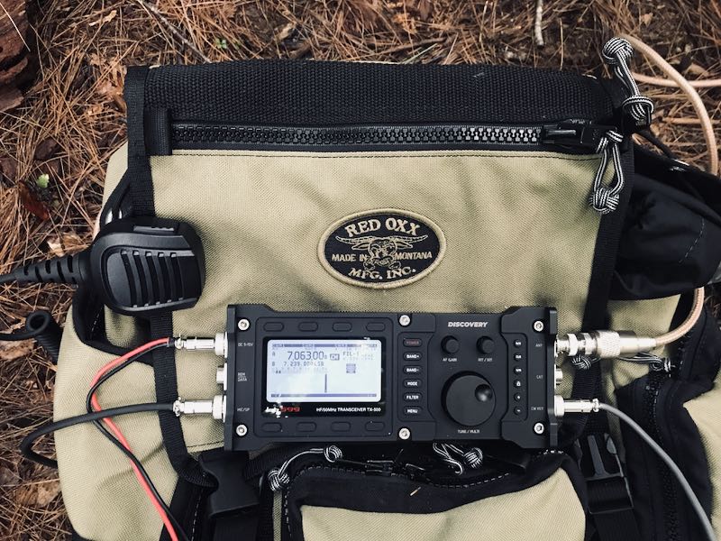
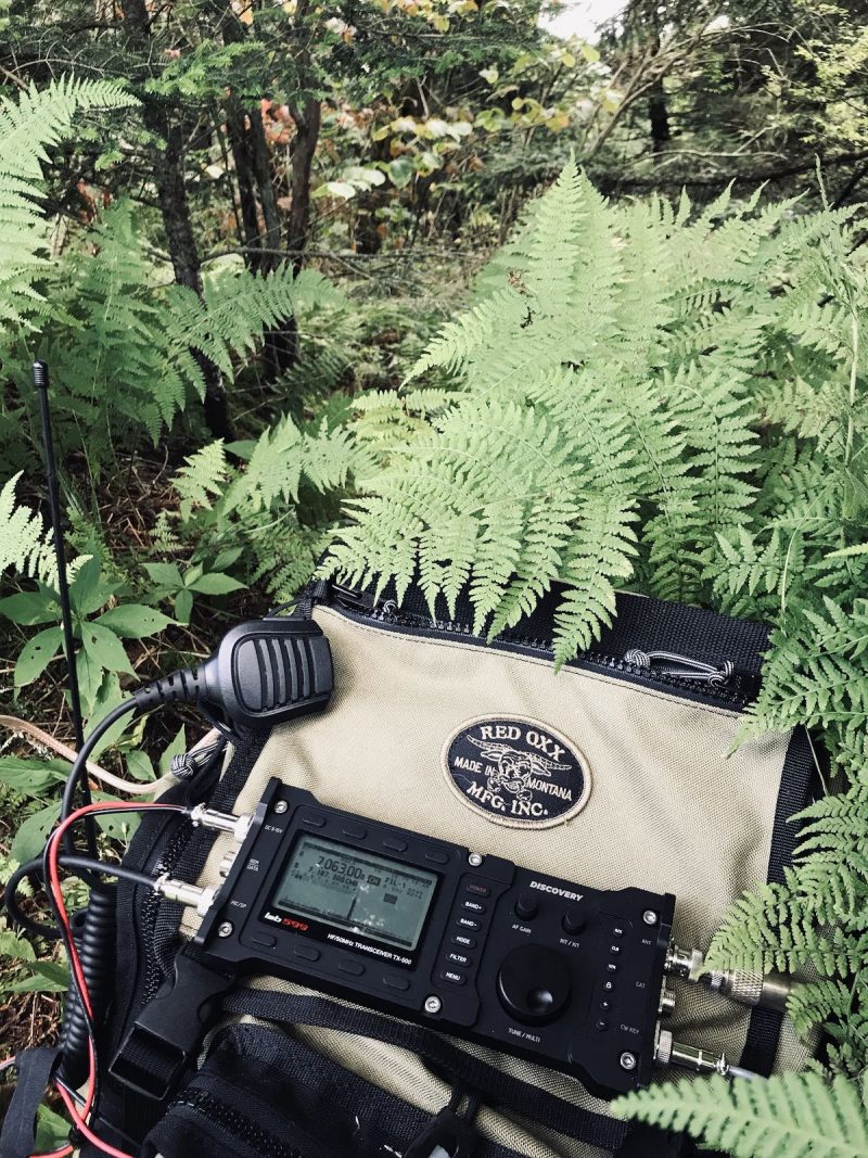
When I operate CW in the field, I tend to place the TX-500 on my backpack and attach the speaker mic to the top flap. It’s worked out quite well.
Audio from the speaker microphone is tinny, but actually well-tailored for voice and Morse Code. For shortwave radio listening, however, that’s another story: you’ll certainly want to connect a proper speaker.
No ATU
The TX-500 does not include an internal automatic antenna tuner. For those used to operating an Elecraft field radio, the Xiegu G90, or the CommRadio CTX-10, for example, this might seem like a major omission.
While it would be nice to have an internal ATU, I’m quite happy to do without one, as all of my field antennas are resonant on the bands I operate. But as a point of comparison, it’s nice when, say, my end-fed antenna isn’t ideally deployed and can’t get that 1:1 match on the 40 meter band; with my KX2, I can simply push the ATU button and the rig solves the match.
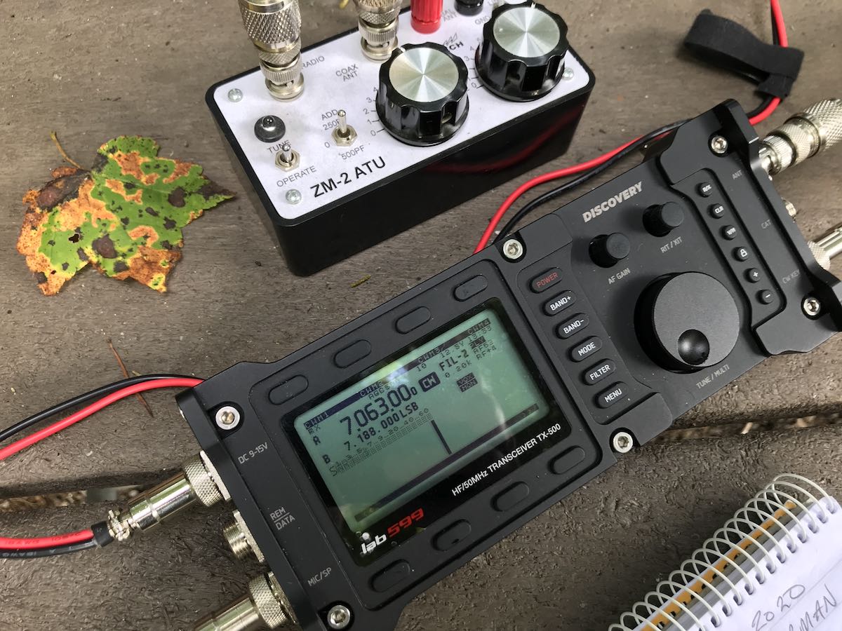
I carry a simple Emtech ZM-2 balanced-line manual antenna tuner, just for when an ATU is needed. But out of the eight field activations I’ve done thus far with the TX-500, only once did I add the ZM-2 to the mix, and just to bring the match from a 2.3:1 to 1:1. If I wanted an external automatic antenna tuner, I’d grab an Elecraft T1. It’s a gem of an ATU.
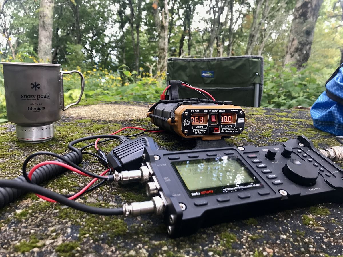
No internal rechargeable battery (yet!)
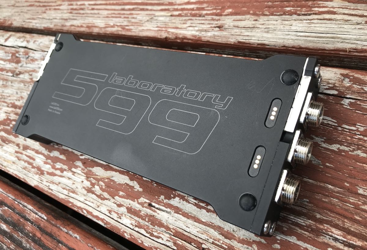
The TX-500 transceiver doesn’t have an internal rechargeable battery option like the CommRadio CTX-10 or Elecraft KX2. But like the new Icom IC-705 sports, lab599 is designing an attachable rechargeable battery pack that will fit the TX-500 beautifully. You can see the recessed battery connections on the back/bottom of the TX-500.
As of this time, no availability date for this future option has been announced, but I can confirm it is indeed in the works.
What makes the TX-500 unique
For some, the idea of a radio which lacks an internal speaker and ATU might lead the rapid decision to dismiss it outright. I would urge those folks to continue reading, however; the TX-500, due to some very unique features, has certainly carved out a market niche, and thus is worth the consideration.
Rugged, weather-resistant body
As I mentioned above, the TX-500 has a solid aluminium-alloy body which gives it a distinctly solid feel. There are no gaps between chassis plates, and all of the buttons, knobs, as well as the encoder are sealed to prevent water penetration.
The TX-500 design smacks of military-grade construction, but in truth is a blend of military specs and amateur radio functionality. For example, the chassis is, if anything, over-engineered for most amateur radio applications. If I owned the TX-500, I wouldn’t hesitate to take it on extended hiking trips, even in dubious weather. Of course, that’s not to say I’d intentionally leave the rig out in heavy rain. But I wouldn’t worry about a sudden rain shower ruining my radio. If this were a military radio, it would have fewer controls and likely be somewhat channelized. Instead, the TX-500 has the full set of controls, features, and filters you’d expect in an amateur radio transceiver with a military-build quality.
In short, it might appear to belong to rugged military kit, but it’s very much designed for the demands of amateur radio operators.
Although the TX-500 is incredibly solid, it’s also lightweight. I weighed the radio with its speaker/mic and power cable. The total weight was 1 pound, 7 ounces. One of my blog readers noted that such a lightweight radio would simply break in half if they hit it over their knee. My reply? No way. In fact, I’m willing to bet such an action could break your knee cap! Please don’t try this, you’ll surely regret it.
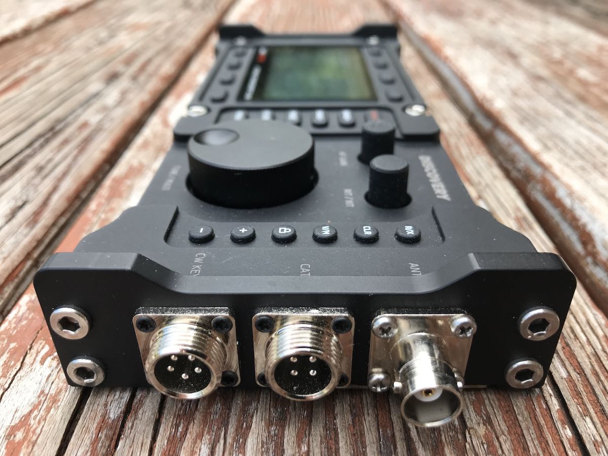
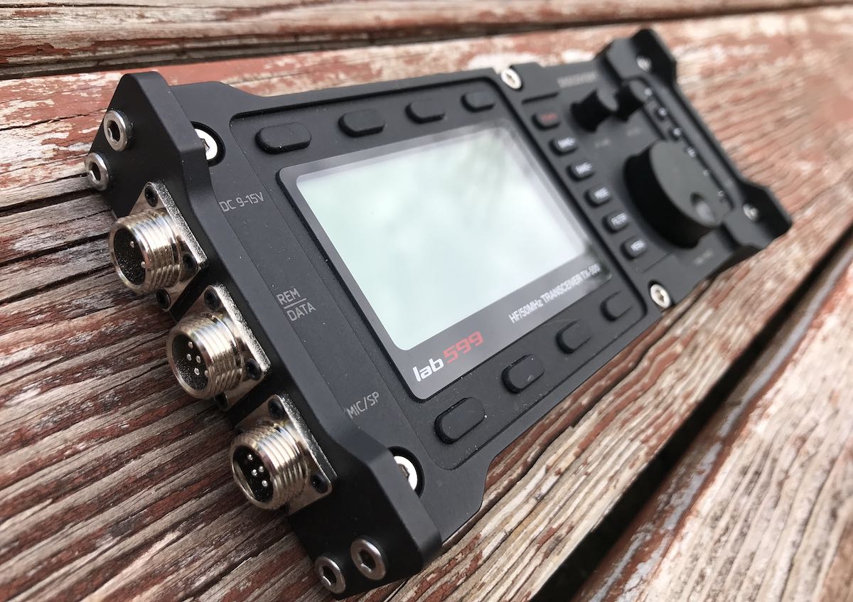
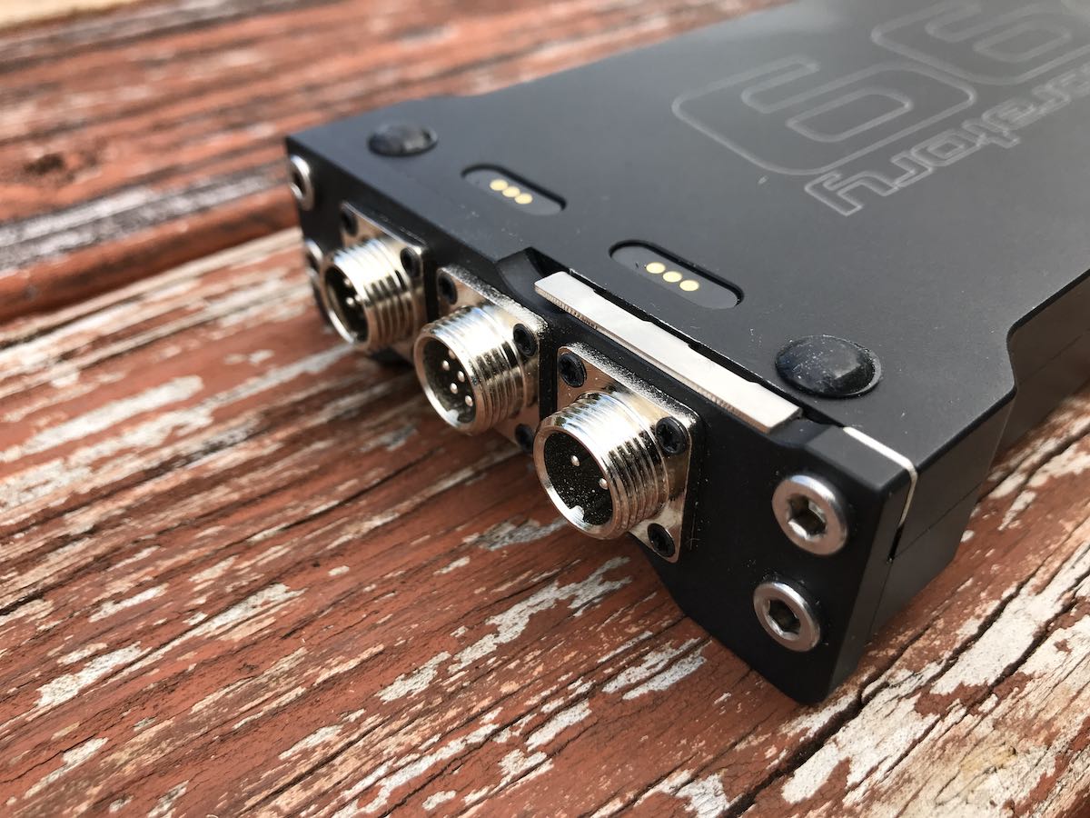
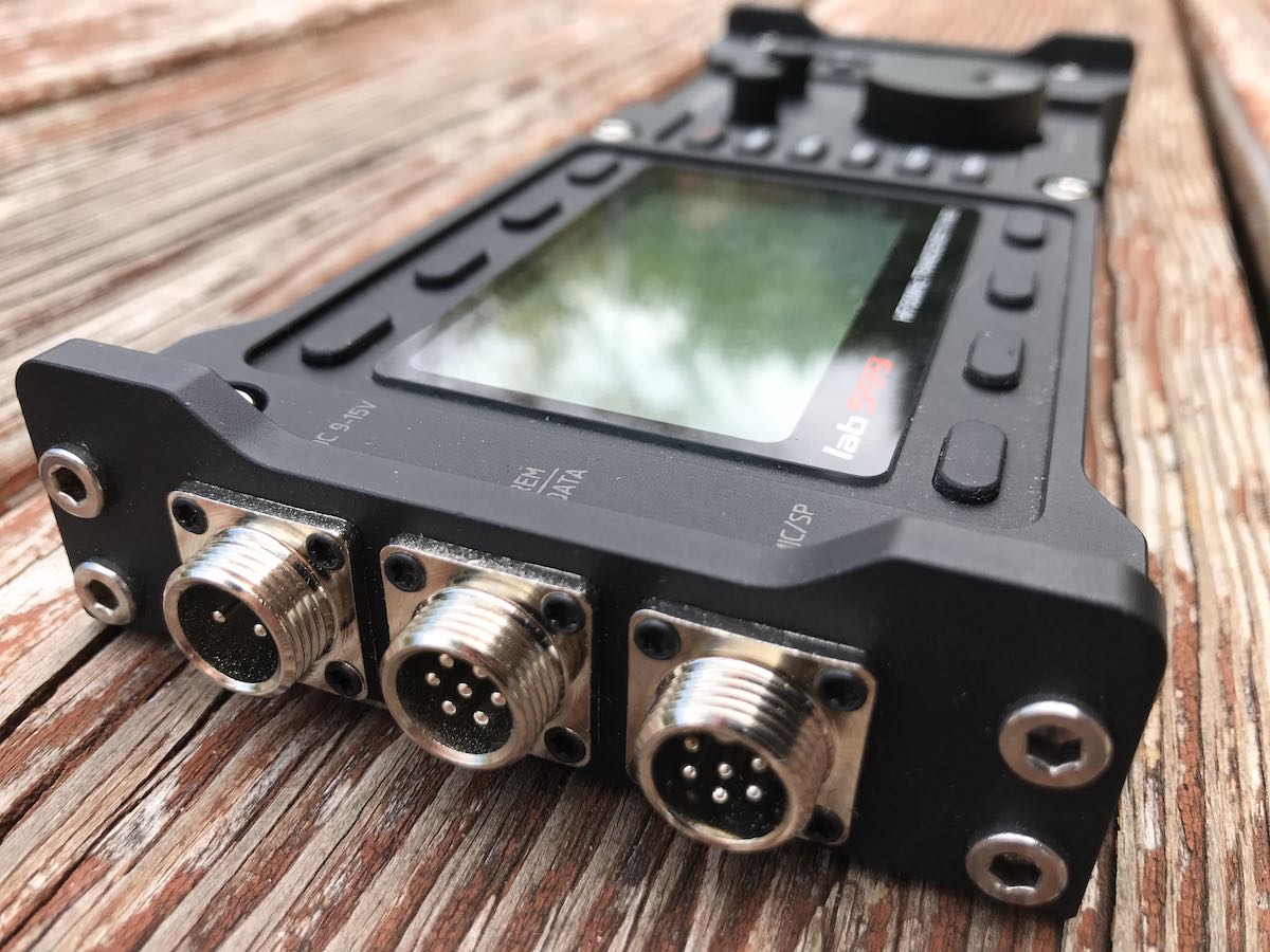
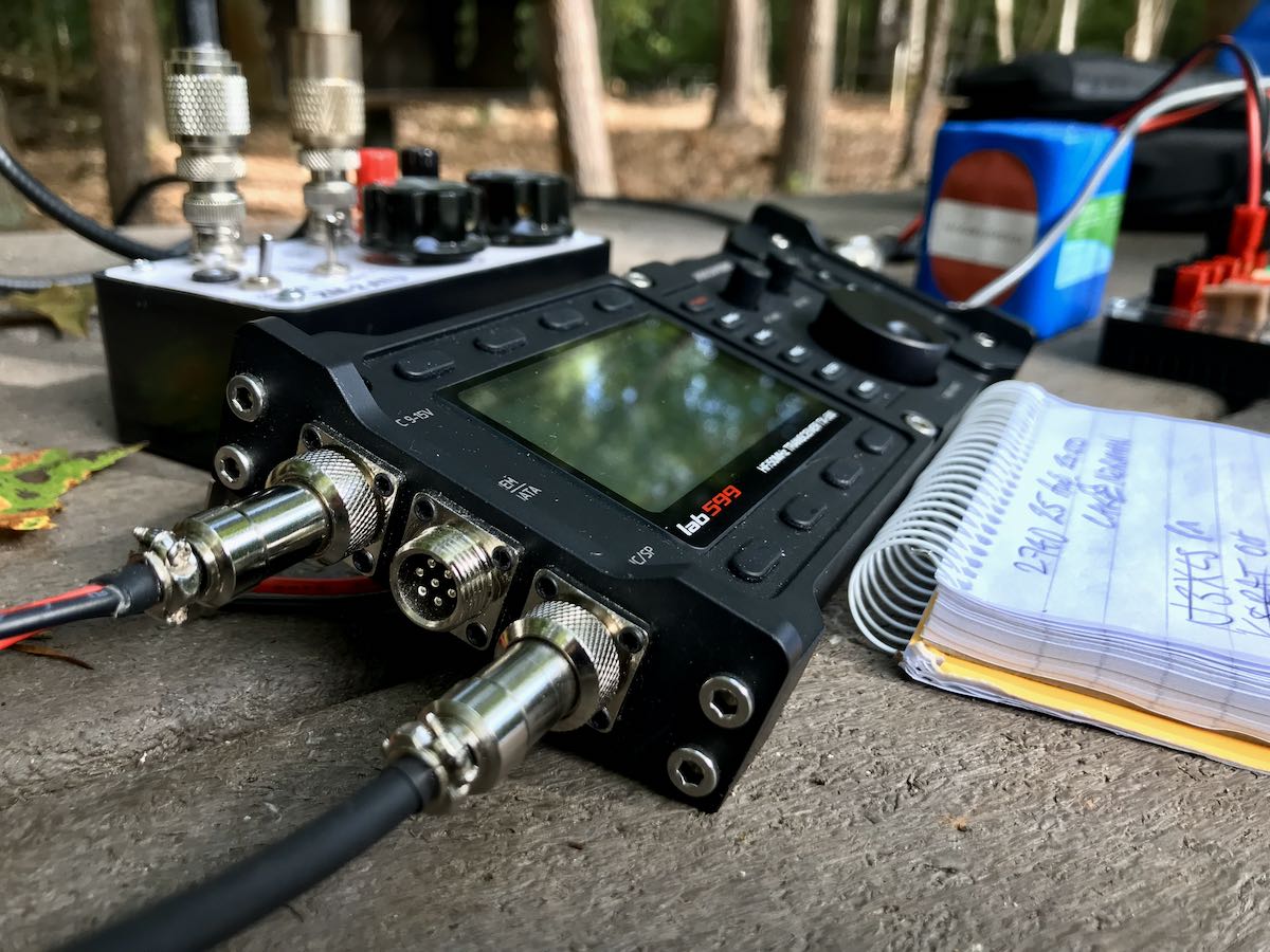
Connectors
One of the most frequent questions readers ask about the TX-500 is why its makers chose to include non-standard (to radio) GX12mm multi-pin aviation connectors for the rig’s power port, CAT control, data, CW, and speaker/mic…?
The answer? In brief, it’s water resistance.
GX12mm connectors allow for a watertight connection and protect the radio very well from water intrusion. And while GX12 connectors aren’t standard in the world of amateur radio, they are certainly standard in aviation, commercial, and military applications. These connectors are widely available online and there are even mom-and-pop ham radio retailers like W2ENY selling premade TX-500 cables and adapters on his eBay store and website.
Meanwhile, the TX-500 uses a standard BNC antenna connection for antennas, which I’m very pleased to note.
LCD screen with spectrum display
Most of us now expect modern SDR-based transceivers to sport a full-color backlit––and sometimes touch screen––display. In the field, however, color TFT displays can be incredibly difficult to read in full sunlight.
Like the Elecraft K and KX series radios, lab599 opted for a more simple, higher contrast monochrome backlit LCD display. This pleases me to no end, because I much prefer this type of display in a POTA or SOTA field radio just because it’s so much easier to read in bright outdoor light. Also, I feel touch screens aren’t as well suited for hiking, camping, and heavy field use–they’re more vulnerable to being damaged.
The TX-500 LCD is chock-full of information and very responsive. The spectrum display (no waterfall) is fluid and useful, as effective as any full-color display.
Benchmark current drain
When operating on battery in the field, current drain in receive mode is a major factor. The more slowly you can sip from the battery while the radio is receiving, the longer play time you’ll have. I like my general coverage field radios to consume less than 400 milliamps.
My benchmark general coverage radio, the Elecraft KX2, consumes a mere 135-140 milliamps at moderate volume levels. I can operate for hours with a compact battery. The TX-500 consumes between 110-120 milliamps at a moderate volume level; yes, even a smidge better than the KX2. The company lab599 actually specs out this radio at 100 milliamps, and I’m confident one could achieve it simply by using headphones.
While there are transceivers like my MTR-3B which have even lower current drain, they’re CW-only and lack general coverage reception, large displays, and the like. Thus, the TX-500 sets a benchmark for general-coverage full-featured portable transceivers in terms of drain.
On the air
In terms of operating the TX-500 in the field, I have very few complaints. The menu system is very easy to use and is intuitive. I never needed to reference the manual––but if you do, the manual is one of the best I’ve seen from a new transceiver manufacturer (click here to download he manual and other TX-500 files).
The buttons are easy to press. They have a tactile feel and proper response so you know you’ve properly engaged a setting. The features and buttons are well spaced, too, and the thin-but-wide chassis actually provides generous surface area for the controls. One could easily operate the TX-500 with gloves on, should it be necessary in cold climates or winter conditions.
As mentioned earlier, the TX-500 does not have an internal ATU option like the Elecraft KX2 or the Xiegu G90. For some, this will be a huge negative against the TX-500. Good internal ATUs allow operators to use a much wider array of antennas in the field–including random wire antennas–and I’ll admit that I’ve gotten quite used to having one in my KX2 and KX3. But again, to get the most signal per watt, I use resonant antennas in the field these days, so very rarely need or employ an ATU.
So how does the TX-500 play? In the following sections I’ll address putting the TX-500 on the air as both a CW and SSB operator. Note that I did not have the opportunity to test the TX-500 on digital modes––like PSK-31 and FT8––as my pre-production model lacked the necessary cables, nor was building my own possible during the week of testing.
CW
Of the (very few) videos that were produced prior to the TX-500’s release, a couple of these were made by a CW operator in Russia. Unfortunately, I was able to glean little information from those videos. I was very eager to try the TX-500 in CW mode as this has become my preferred method of activating parks for POTA.
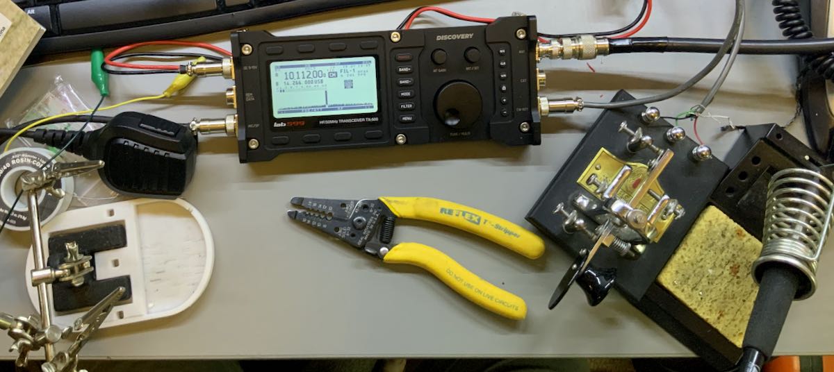
When I received the TX-500, it did not come with the same cables that Ham Radio Outlet will include. It did, however, include the 5 pin connector for the CW port, so I simply soldered a cable and connected it to the terminals on the back of my Vibroplex single lever paddle.
This way, I was able to avoid purchasing and attaching a three conductor ?” female plug. (This intervention did mean that, in the field, my key would weigh more than the transceiver–!)
But the question every CW operator has asked me is “Does the TX-500 support full break-in QSK?” Full break-in QSK allows instantaneous transmit/receive recovery time, so that even higher speed operators can hear between sent characters while operating. This means if another op wants to grab your attention while you’re operating––or, in the parlance, “break in”––you’ll hear them in the middle of sending a word.
Unfortunately, the TX-500 does not support full break-in QSK. Instead of being based on pin diodes (like the Elecraft KX series) the TX-500 uses a relay. This means that you’ll hear a relay click each time the radio switches between transmit and receive.
In the past, I’ve reviewed transceivers in which the relay click was honestly quite loud, even annoyingly so. Fortunately, the TX-500 has such a solid and well-sealed body that I find the relay sound to be the least distracting of any relay-based transceiver I’ve tested. You can still hear it, but it’s reasonably soft. So that you can hear what I mean, in this video, you’ll hear the relay clicking when I point the camera toward the rig.
The T/R recovery time on the TX-500 is quite rapid. While I can’t hear audio between characters sent within a word, I can hear between words when the relay is set to the quickest recovery and I’m operating around 17-20 WPM. If, however, you operate at higher speeds and prefer full break-in QSK, you may wish to give the TX-500 a pass.
The TX-500 comes with a full complement of CW operation adjustments, like Iambic type, straight key, weight ratios, sidetone volume, and the like. One oddity is that it doesn’t measure CW speed in words per minute. It uses a completely different scale that measures with a much wider number range. I set my speed to “97,” which I guessed might be an equivalent of about 17 or 18 WPM. While I first thought this feature odd, I soon came to appreciate this specificity because without the restriction to 1 WPM increments, as with most transceivers, it gives the op more flexibility to adjust speed.
I discovered that the TX-500 can handle dense RF environments while doing a park activation during a CWT contest. Even with a 400 Hz filter engaged (and it could have been much narrower), the TX-500 effectively blocked adjacent signals. To demonstrate, I made the following short video in the field:
Rob Sherwood recently tested the TX-500 and published the results on his excellent receiver test data table. Although very respectable, I expected the TX-500 to sport more competitive numbers based on my “real-world” tests. Still: this is a field radio. Not a rig I’d reach for to win the CQ WW contest. In field operations, TX-500 is a brilliant performer and has better overall specs than a number of popular radios including the immensely popular Yaesu FT-891, for example.
CW ops should keep in mind that the TX-500 has no internal speaker, so to operate you’ll either need to connect an external speaker, the supplied speaker/mic, or headphones. Since I primarily operate with headphones, this will be no inconvenience to me. As there was no headphone connector with this pre-production model TX-500, I simply used the speaker mic for all operations.
When the TX-500 was first released and HRO made a product page on their website, the rig had no CW memories, which I truly rely on for field operations. CW memories allow me to manage my logging workflow, pre-format responses, and CQ calls without having to manually key everything. Lab599 must have noted this omission, and by the time I received my evaluation unit, a firmware release had been issued which added CW memories. I immediately performed a firmware update (a simple process, by the way). I even passed along some suggestions and critiques of the CW memory keyer; lab599 immediately made adjustments and fixes as needed for optimal performance.
If you’ve ever saved CW memories in a radio, you may have found it frustrating to achieve the right spacing for the radio to provide a proper playback. It often takes me multiple tries, for example, to save a park number into my KX2. The TX-500, fortunately, is very forgiving and I found it very simple to set CW memories in the field.
While not on the radio I used at time of evaluation, I understand lab599 is planning to add a “beacon mode” for calling CQ, as well.
All in all, I find the TX-500 a pleasure to operate in CW mode. Indeed, 75% of all of my logged stations were made in CW mode.
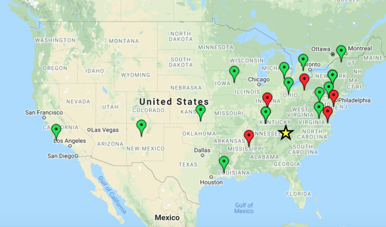
Speaking of which, funny story…I activated Pisgah National Forest and the Blue Ridge Parkway in the mountains of western North Carolina. I hammered out 13 logged stations from Maine, Vermont, Ontario, Illinois, Kansas, Louisiana, Florida, and several states in the middle of that footprint.
On this map, all of the green pins below were CW contacts and made with one watt of power. The red pins are SSB contacts with 10 watts. The yellow star is roughly my location:
I switched to SSB mode to make a few phone contacts, and called CQ. No one heard me. I was puzzled…but suddenly I realized I had left my power setting at 1 watt! The previous day, I was running tests into a dummy load. Yes, all of those CW contacts were made with truly low power, indeed!
SSB
The TX-500 has a lot to offer the SSB operator. I’ve gotten great reports from my SSB contacts, and have even listened to my own signals via the KiwiSDR network.
The TX-500 includes all of the features a phone operator would expect, such as compression and gain control. Of course, you can enable VOX operation if you’re using your favorite boom headset. The TX-500 allows you to not only to change the receiver EQ settings, but also transmit EQ settings. This means you can tailor your TX-500 to get the most audio punch per watt while operating phone. Very nice!
The TX-500 ships with a rugged, simple speaker microphone. I’ve been using this exclusively during the evaluation period, and have been very pleased with it. The mic even has a protected mono audio out port on the side, should you wish to attach a different external speaker.
Perhaps the only negative from my point of view as a phone operator is that the TX-500 lacks a voice memory keyer. While it has this feature for CW, it lacks it for SSB.
UPDATE – February 4, 2021: lab599 has just added voice memory keying in their latest firmware update! The TX-500 now has two voice memory memory slots of 20 seconds each: VXM1 & VXM2. After performing the firmware update, it’s easy to record voice memories:
Navigate to CW memory menu.
Press and hold VXM1 or VXM2 to record. REC icon on.
Press the associated VXM key again to stop.
Press VXM key to Play. PLY icon on.
Press VXM key to stop.
To put this in context: all recent Elecraft rigs have voice memory keying; the new IC-705 includes this as well. Even the Yaesu FT-891, which is one of the most affordable compact transceivers in the Yaesu line, has voice memory keying. For POTA and SOTA activators, voice memory keying is huge, as it frees you to do other things like log, eat a sandwich, or talk to others while calling CQ. It also saves your voice. For example, on the KX2, I record a CQ message like “CQ POTA, CQ POTA, this is K4SWL calling CQ for Parks On The Air;” I save the message to memory location #1, then play it back in “beacon mode.” The KX2 will continuously transmit my voice CQ message with a few seconds between each call. When someone answers my call, I can easily pause the beacon by hitting the PTT switch or one of the transceiver keys.
I do wish the TX-500 had this handy feature, but because of a lack of internal storage, I don’t expect it will be added. This isn’t a deal-killer for me, as I could add an external voice memory keyer, but it certainly would make for ideal SSB field-radio operating.
Shortwave broadcast listening
Of course, since I’m a hardcore shortwave radio listener and the TX-500 has a general coverage receiver, I did quite a bit of casual shortwave radio listening during the week I had the radio in the shack.
What’s great about the TX-500 is that it has a very capable receiver with a low noise floor and superb sensitivity and selectivity. The preset filter bandwidths can be adjusted in all modes including AM. I have the widest setting at 10 kHz, which gives one proper fidelity with strong shortwave broadcasters.
Here’s a link to a quick video I made showing how the TX-500 sounds while tuning around the 31 meter band. Note that the amplified speaker I use for this demo is limited in fidelity and I recorded this using an iPad. Still, I think you’ll get a decent idea how well the TX-500 plays as a shortwave receiver:
The TX-500 will tune to the bottom of the AM broadcast band as well, and I’ve spent time listening there. I did not have the time to do a deep dive, but I find that the TX-500 performs rather well in those low bands…a rarity for a ham radio transceiver.
Summary
Every radio has its pros and cons. When I begin a review of a radio, I take notes from the very beginning so that I don’t forget those initial impressions. Here’s the list I created over the time I’ve spent evaluating the TX-500.
Pros:
Solid, rugged chassis with weather/water resistance and built-in low-profile side protection panels
High-contrast LCD display that’s responsive and easy to read in the field
Excellent receiver sensitivity, selectivity, and low noise floor
Full complement of features and adjustments expected in a modern transceiver
Multiple adjustable filter settings
Very low current drain for a full-featured general coverage transceiver (100-120 milliamps)
GX12mm connections provide further water protection (see con)
CW memory keying
Easy firmware upgrades with supplied USB cable and lab599 firmware application
For US customers: a Nevada-based service center for repairs (no word yet on similar centers elsewhere)
Per lab599 announcement, hopefully available next year: an attachable TX-500 battery pack
Cons:
No built-in speaker
No internal ATU option
No full break-in QSK CW operation (although relay is quiet and audio recovery fast)
GX12mm connections are non-standard on amateur radio transceivers for water resistance, thus one might need to purchase or build cables for non-standard accessories (see pro)
No voice keyer for phone operation Update: this feature was added in the February 4, 2021 update!
No notch or auto-notch filters at time of publication (these may be implemented in future firmware upgrades) It does indeed have a notch filter now!
Fold-out feet could scratch soft surfaces, such as wood
Conclusion
Would I buy the TX-500 myself? Well, since I’m a heavy field operator, yes, without hesitation. Moreover I believe the $800 price tag is reasonable for a radio with its feature set and rugged military-spec type design.
I confess, I have been looking forward to getting the TX-500 in hand for a year now. So when HRO put up a product page and started accepting orders, without much thought, I placed mine. Yet within an hour, I was rethinking my decision, and soon I called to cancel it. Why? A bit of buyer’s remorse. For although instinct told me I’d like the rig, common sense said I was getting ahead of myself. The truth was, at that time the TX-500 didn’t have CW memory keying, and without that, I knew this field radio would not get a lot of use during my park and future summit activations. Moreover, I’ve no less than six eight QRP transceivers––not to mention an Icom IC-705 on order for review––so it wasn’t as though the need was great. Instinct or no, I felt I’d made the decision in haste, and my head said my heart should take a few beats before committing.
Yet, after receiving the TX-500 loaner, and taking it to the field––and, of course, lab599’s addition of that all-essential memory keying––all of a sudden the TX-500 became much more appealing. And I’ll admit, this radio really grew on me over that evaluation week (ah, the dangers of reviewing radios…you do often become attached). There’s also been comfort in knowing the TX-500 wouldn’t be harmed should I be caught in a pop-up shower and anxious for the safety of my equipment. But there’s something more: it turns out my initial instincts were correct. I just happen to really like this radio. The way it feels and functions suits me as an operator and its performance exceeds expectations. And that’s a thing I couldn’t have known until I gave it a spin.
While no radio is perfect, I nonetheless suspect the TX-500 will gather a loyal customer base soon; indeed, it had a following well before anyone laid hands on it. Including me.
So now I am seriously considering purchasing the TX-500 for keeps.

 PC keyer and AM modulator: A 15-components versatile keyer and powerful PSU modulator for the EMTX (Emergency Transmitter)