
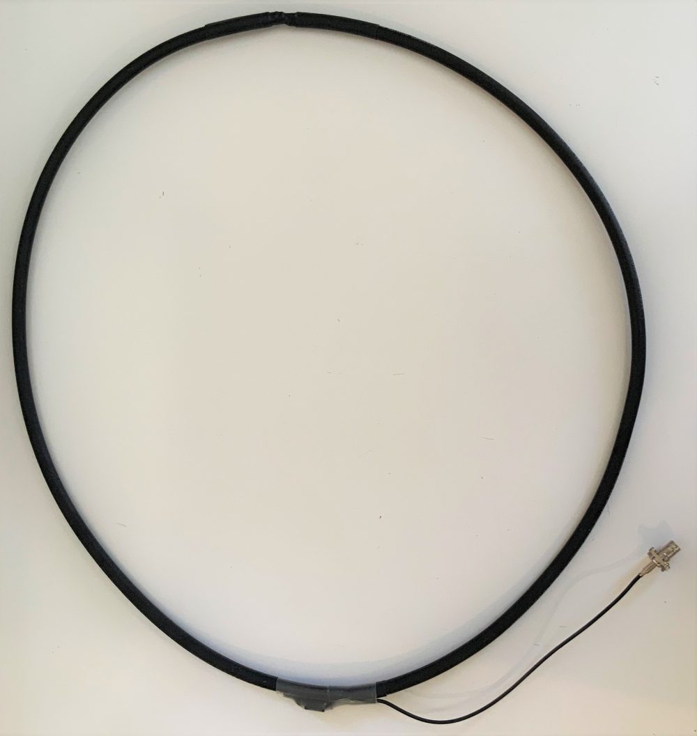
 I’ve gotten an number of inquiries from SWLing Post readers asking for a step-by-step guide to building the passive loop antenna I’ve mentioned in a number of previous posts. This antenna is the homebrew version of the commercially-available Airspy Youloop.
It works a treat. And, yes, folks…it’s fun to build.
There are a number of loop designs out there, and to distinguish this one, I’m going to henceforth refer to this loop as in the title above: the Noise-Cancelling Passive Loop (NCPL) antenna.
Before we start building, a little antenna theory…
I’m neither an engineer nor am I an antenna expert, so I actually turned to Airspy president and engineer, Youssef Touil, to learn how, exactly, this passive loop works. Youssef was the guy who experimented with several loop designs and ultimately inspired me to build this loop to pair with his HF+ Discovery SDR and the SDRplay RSPdx. “The main characteristic of this loop,” Youssef notes, “is its ability to cancel the electric noise much better than simpler loop designs.” Got that! [See loop diagram below]
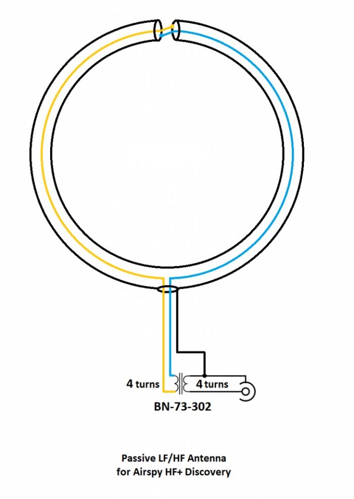
“The second characteristic of this loop antenna is that it is a high impedance loop, which might appear counterintuitive. This means it can work directly with many receivers that have a low noise figure, in order to mitigate the impedance mismatch loss.
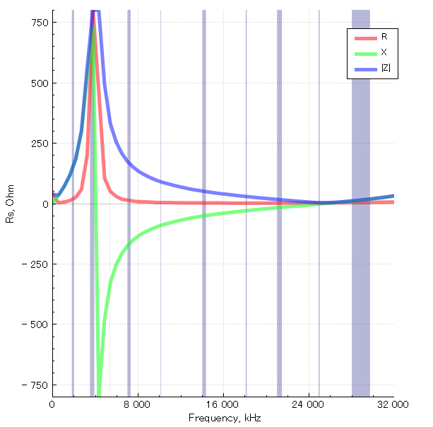
Note the resonance lobe near 4MHz. The resonance frequency is controlled by the diameter of the loop, the parasitic capacitance of the cable, and the loading from the transformer. It happens to be located right where we need it the most.
The transformer is basically a 1:1 BALUN that covers the entire HF band with minimal loss. Our BALUN has typically 0.28 dB loss.
[…]By connecting the center of this outer shield to the ground of the transmission line, you effectively cancel all the electric noise. The BALUN is required for balancing the electric noise, not for adapting the impedance.
[…]If you want to boost the performance in VLF, LW and MW, you can try a different impedance ratio, but this will kill the higher bands.”
What makes this loop so appealing (to me) is that it can be built with very few and common parts–indeed, many of us have all of the items in our junk boxes already. As the name implies, it is a passive design, so it requires no power source which is incredibly handy when you’re operating portable.
When paired with a high-dynamic range SDR like the Airspy HF+ Discovery or SDRplay RSPdx, you’ll be pleased with the wide bandwidth of this antenna and noise-cancelling properties.
If you don’t care to build this antenna, Airspy sells their own version of this loop for a modest $35 USD.
But building an antenna is fun and you can tweak the design to customize performance, so let’s get started:
Parts list
- A length* of coaxial cable for the loop (see notes below regarding length)
- Another length of cable terminated on one end with a connector of your choice as a feed line
- A BN-73-302 Wideband 2-hole Ferrite Core
- Enough coated magnet wire for a total of eight turns on the BN-73-302
- Heat-shrink tubing or some other means to enclose and secure the cable cross-over point and balun. (You may be able to enclose these connection points with PVC or small electrical box enclosures, for example)
- Electrical tape
Tools
- A cable stripper, knife, and/or box-cutter
- Soldering iron and solder
- A heat gun (if using heat shrink)
- Some patience
*A note about loop cable length: Vlado and I made a loop with 1.5 meters of cable. The Airspy Youloop ships with two 1 meter legs that combine to give you an overall loop diameter of about 63.6 cm.
Step-by-step guide
When I first decided to build this loop, it was only a day prior to a trip to the South Carolina coast where I planned to do a little DXing. I didn’t have all of the components, so I popped by to see my buddy Valdo (N3CZ). Vlado, fortunately, had all of the components and was eager to help build this loop. As I’ve mentioned in previous posts, Vlado is an amazing engineer and repair technician, so when I say “we” built it, what I really mean is, Vlado did! But I could’ve done it myself.
This is actually a very simple build––something even a beginner can do, as long as they’re okay with using a soldering iron. It does take patience preparing the loop cable properly. Take your time as you start, and you’ll be on the air in an hour or two.
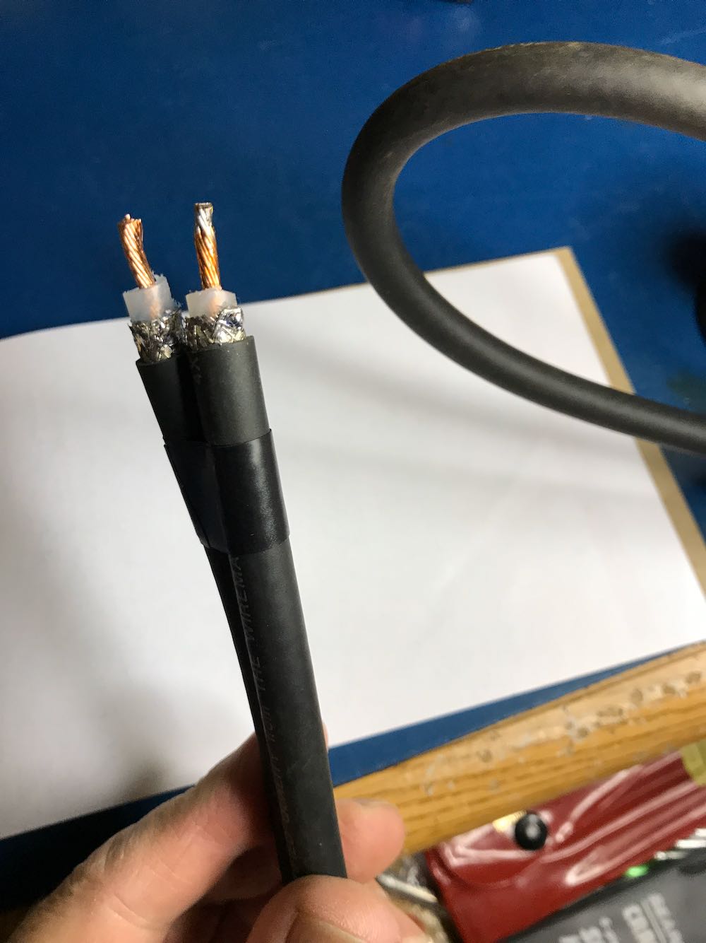
1. Strip the ends of the loop cable.

Although your cable type and diameter may vary, strip back the cable ends roughly like this.
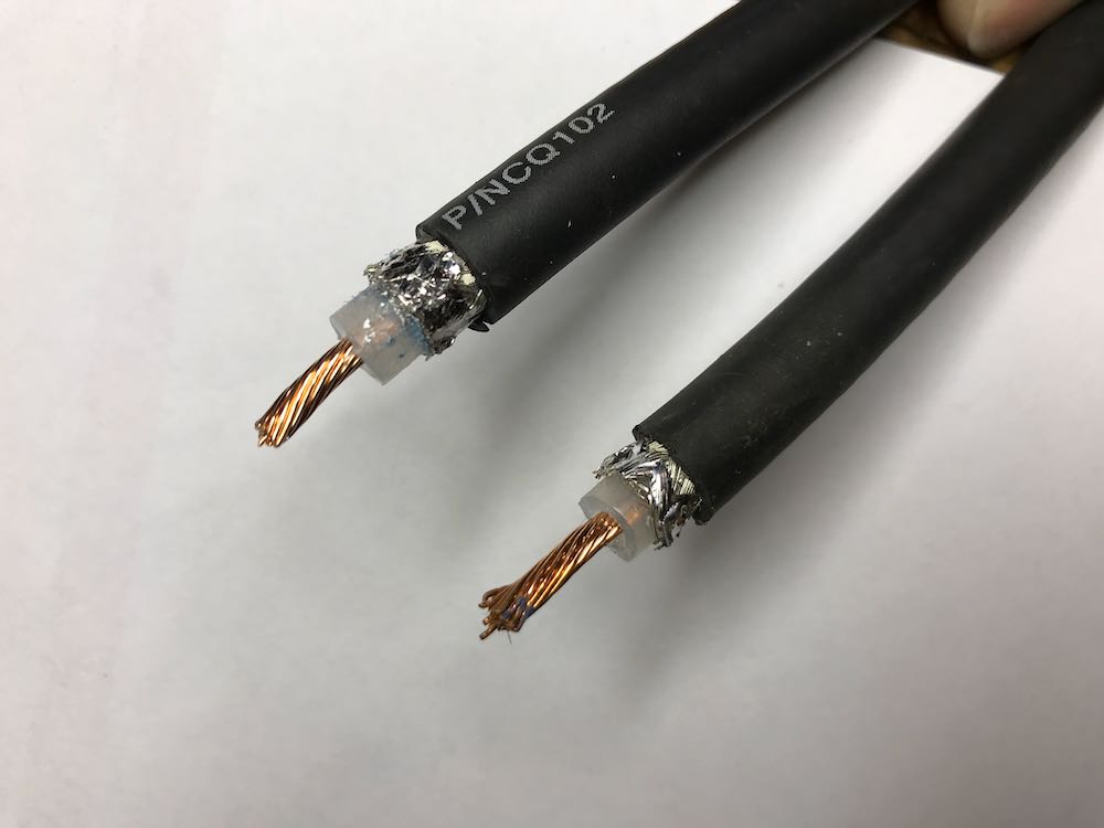 To make finding the middle of the cable easier, we taped off the ends.
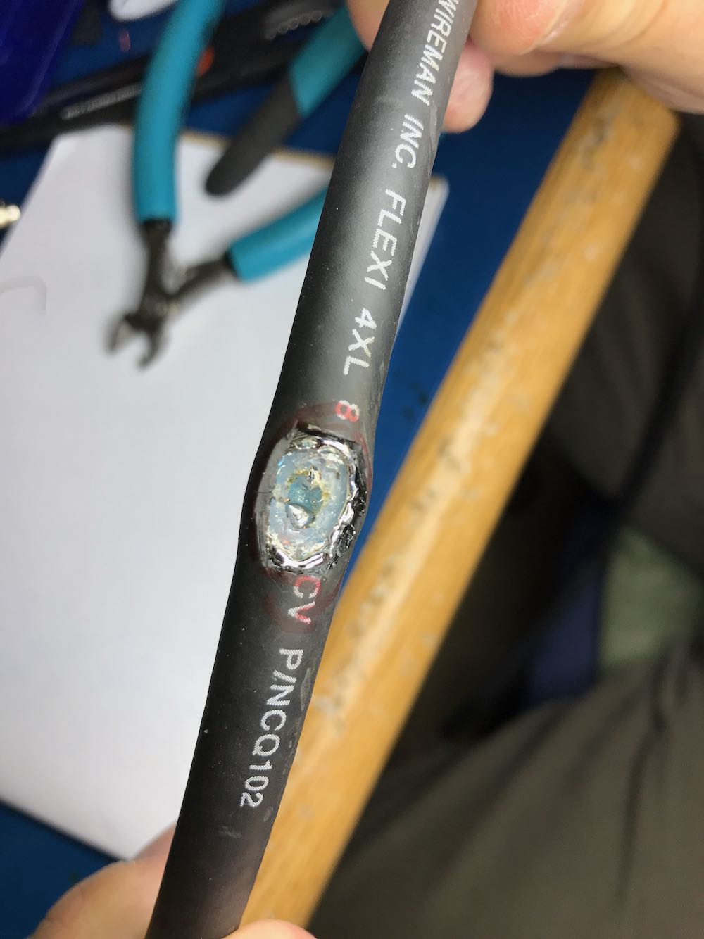
2. Make an opening in the middle of the cable to attach Balun leads to center conductor.
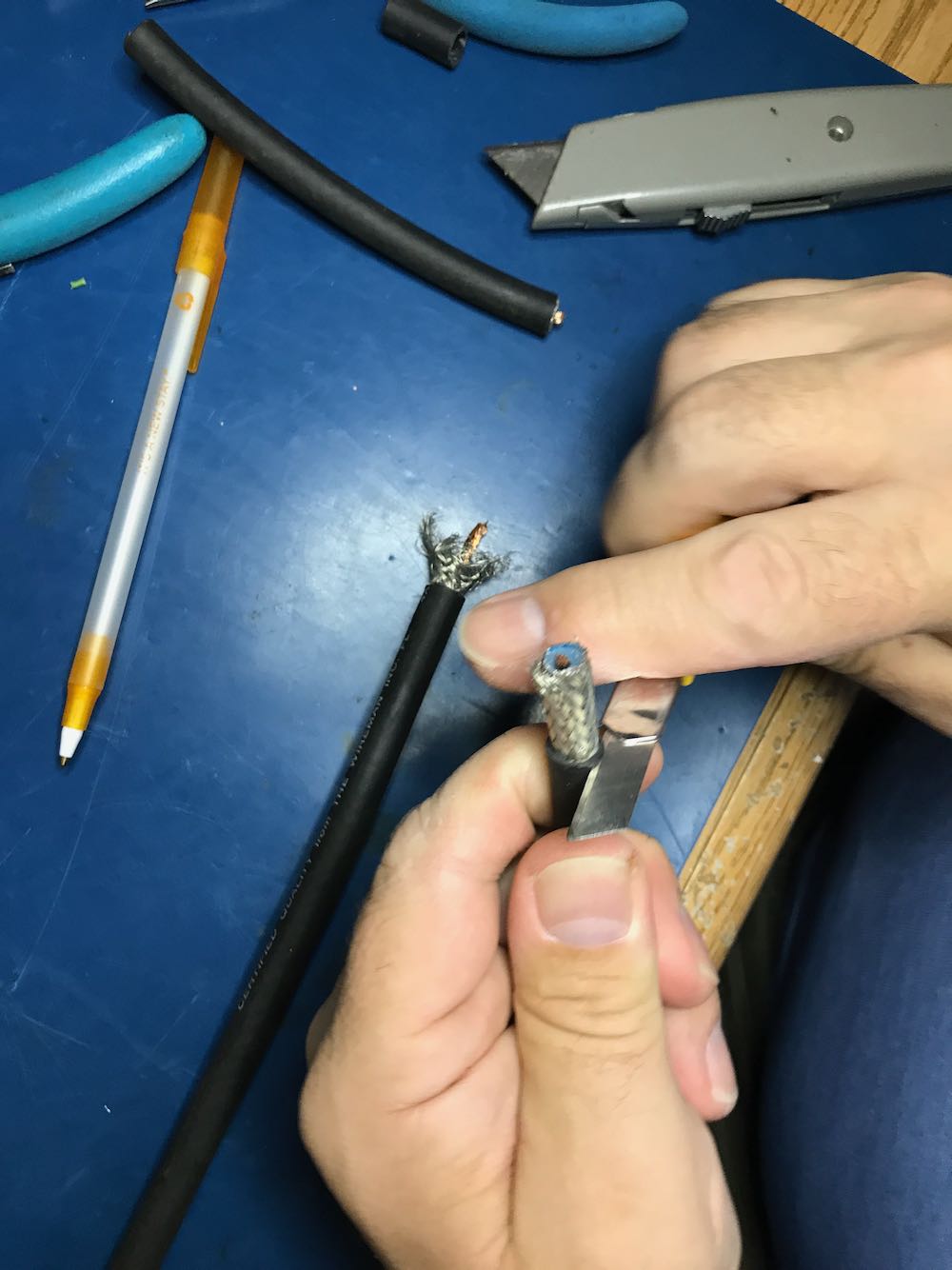
This is the trickiest part of the whole operation. The goal is to create an opening to tap into the center conductor of the cable.
You need to open a hole in the middle of the cable by
1 cutting away a portion of the outer jacket;
2 carefully separating and opening the shielding;
3 digging through the dielectric core, and finally
4 exposing the center conductor of the cable
Try to make an opening just large enough to gain access to the cable’s center conductor, but no bigger. Don’t allow any piece of the shielding to touch the center conductor.
When you reach the center conductor, expose enough of it so that you can clip it in the middle and create an opening to solder your balun leads to both conductor ends.
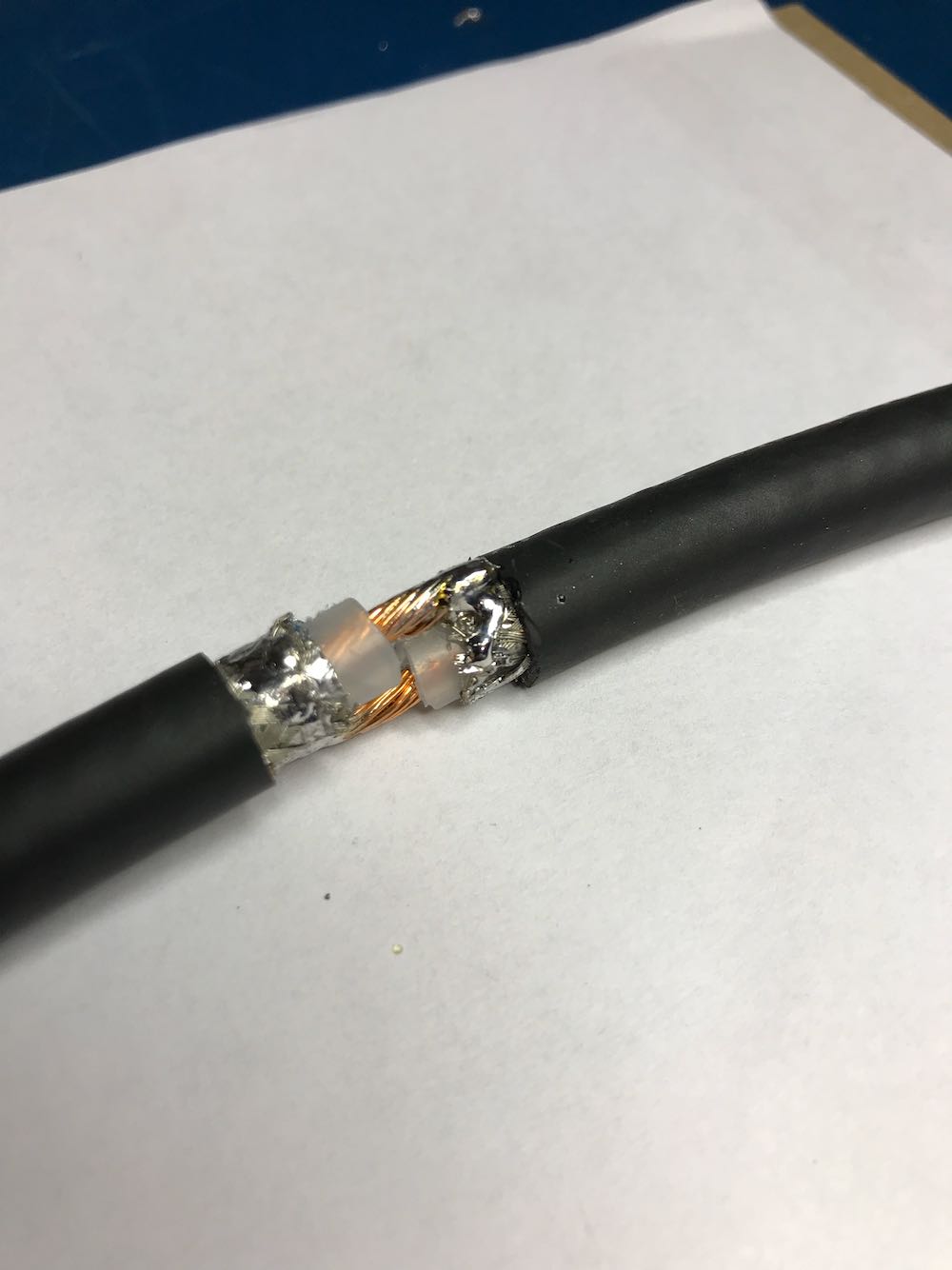
Once you’ve finished with this step, your cable should look something like this…
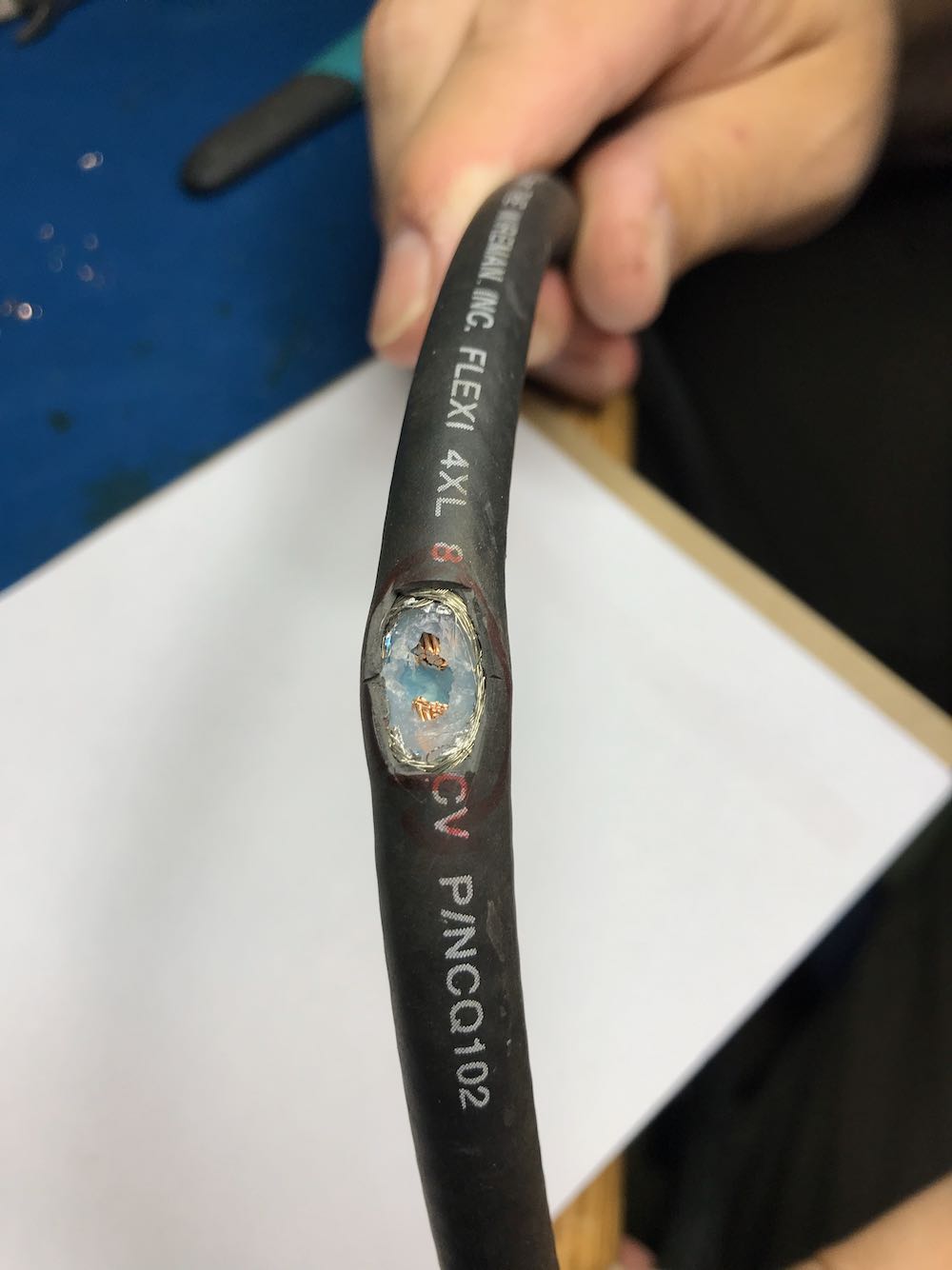
In the photo above, note that the shielding is completely pulled away, the dielectric core has been cut through, and we’ve clipped the center conductor, leaving a gap large enough to solder.
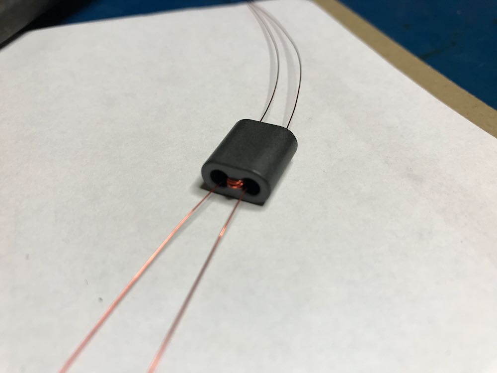
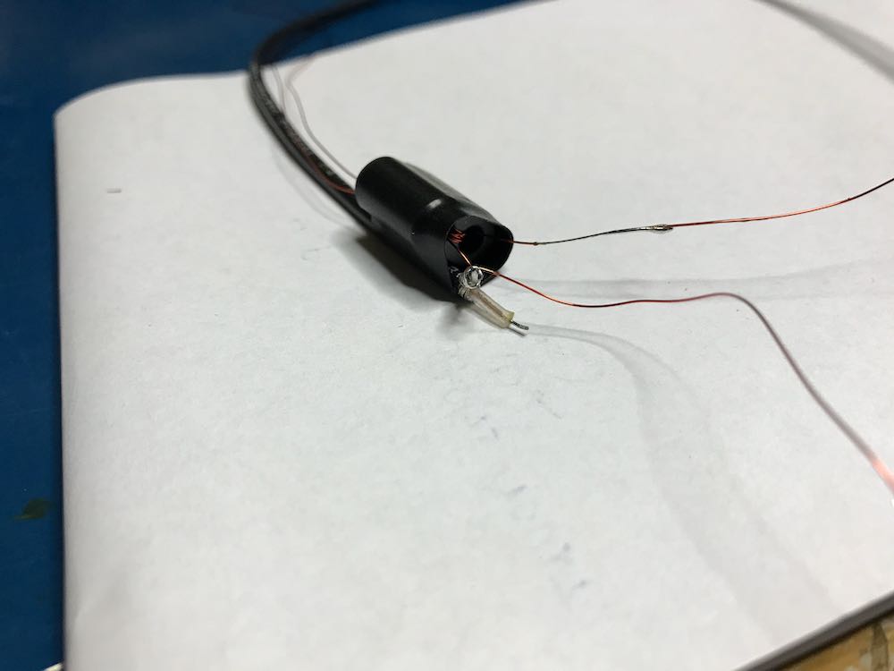
3. Make a 1:1 Balun
Grab your BN-73-302, and with the coated magnet wire, make four windings on one side, and four on the other. It should look like this:
Don’t have a binocular ferrite core like the one above? If you have a broken cable with ferrite cores, you can hack one! Click here to learn more.
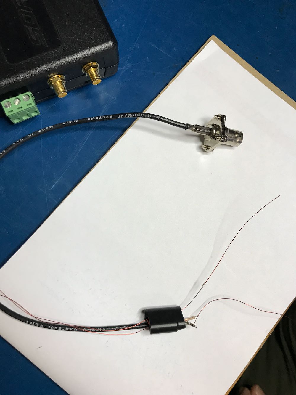
4. Connect the Balun to a feed line.
Vlado just happened to have a BNC pigtail in his shack (he’s that kind of guy), so we cut and stripped one end, then connected the center conductor and shield to one side of the balun. We then enclosed the balun in heat shrink tubing to make it a little easier to attach to the loop later:
Of course, you could also create this junction in a small enclosure box or short cross-section of PVC. There are a number of ways you could secure this.
Youssef also added the following note about the feedline:
To use the NCPL antenna without a preamp, it is recommended to keep the length of the cable below 10 meters. The supplied Youloop 2 meter cable [for example] is sufficient to keep the antenna away from the magnetic interference of a computer or a tablet, and has very low loss and parasitic capacitance.
5. Connect Balun to the coaxial loop.
To make a solid connection, tin both sides of the center conductor. Next, attach the other end of the balun leads to each portion of the center conductor, as seen below:
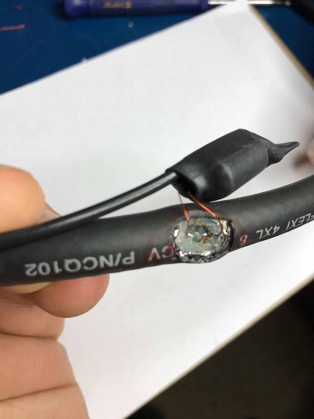
Update: Note in the loop diagram near the top of the page that the ground wire on the output connector connects to the loop coax shielding on the primary side of the balun. I don’t recall that we did this in the build, but I would encourage you to do so. This should result in even lower noise, although admittedly, I’m very impressed with the performance of ours without this connection. Thanks to those of you who pointed out this discrepancy!
6. Secure the Balun/Coax junction.
Since this loop is intended to be handled quite a lot in the field, make sure the junction point of the balun and coax loop is secure. Again, we used several layers of heat shrink tubing since we had some in the shack. 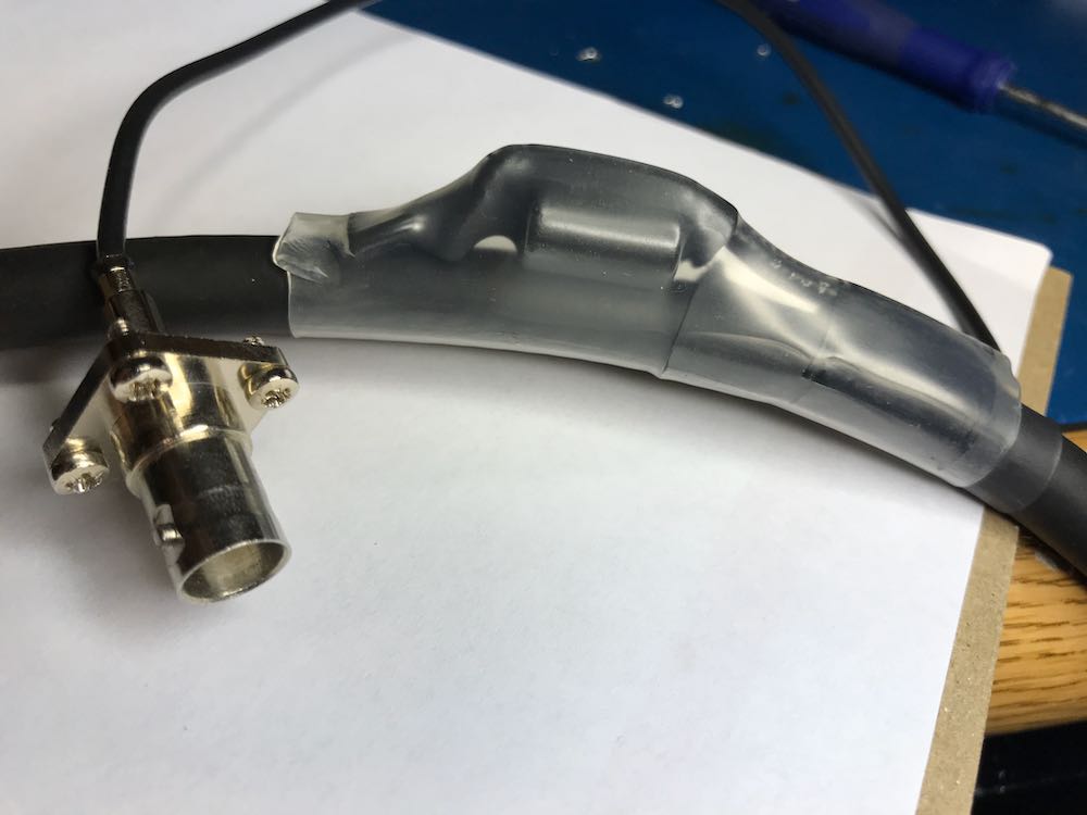
7. Solder and secure the cross-over point.
Next, create the cross-over point of the loop by simply attaching the center conductor of one end of the cable to the shielding on the other end…and vice versa.
Before you grab the soldering iron, however…if, like we did, you’re using heat shrink tubing to secure the cross-over point of the loop in the next step, you’ll first need to slide a length of tubing onto the coax before you solder the ends together. Vlado, of course, thought of this in advance…I’m not so certain I would have!
 Take your time soldering this connection and making it as solid as you can. If you solder it correctly, and you’re using a high-quality cable as we did, the cross-over point will be surprisingly durable. If you’re using a thinner cable, simply make sure the connection is solid, then use something to make the junction less prone to breaking––for example, consider sealing a length of semi-rigid tubing around this point.
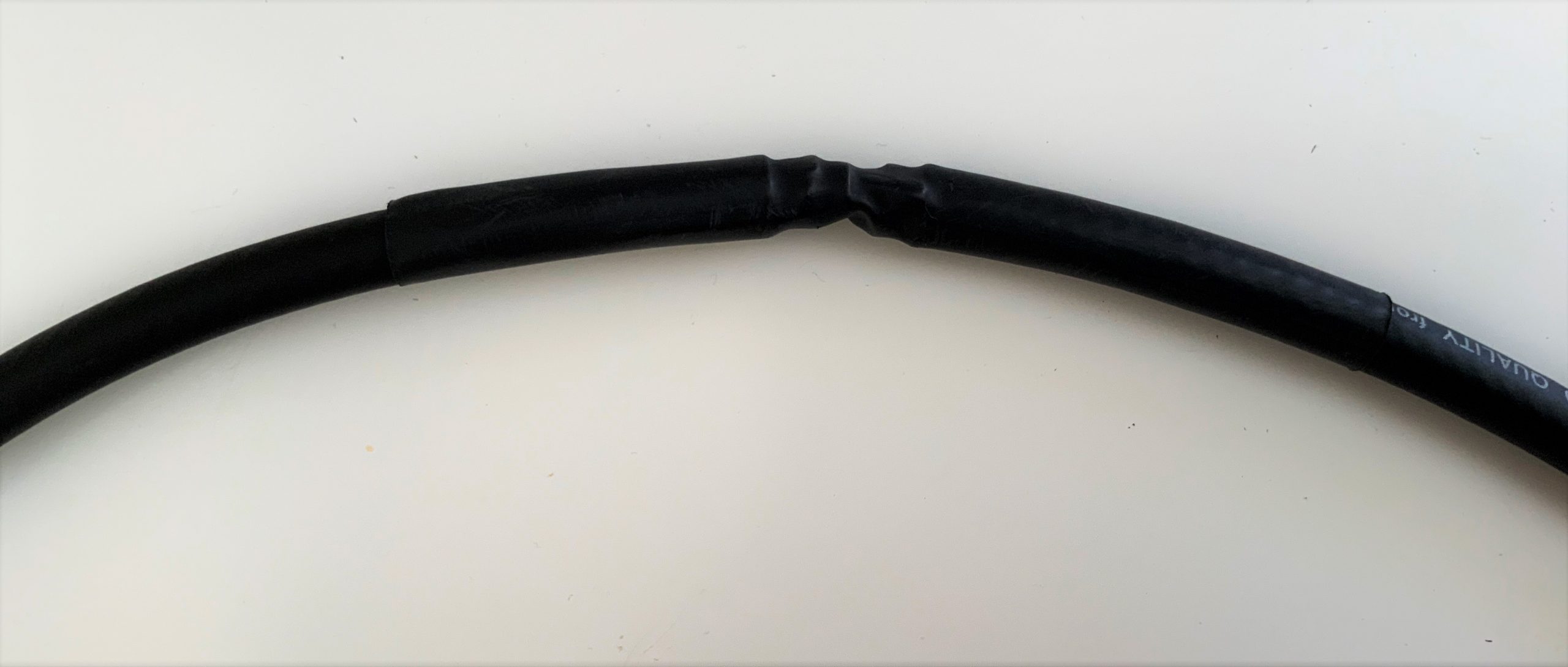
Vlado cleverly added heat shrink tubing around the cross-over point to protect and secure it.
You’re done!
That’s all, folks! Now you’re ready to put your loop on the air.
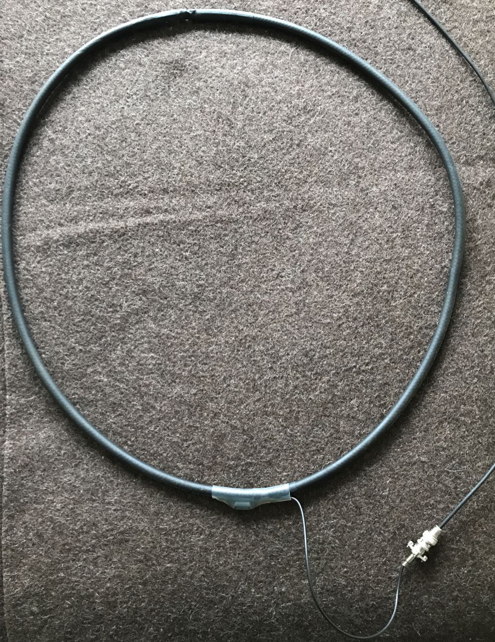
Depending on what type of cable you used for this loop, you might require or prefer some sort of dielectric structure to support the loop so that it maintains the ideal round shape. My loop maintains its integrity pretty well without supports. I’ve supported it a number of times with fishing line/filament from two sides (tying on at 10 and 2 o’clock on the loop). That seems to work rather well.

In this setup, I simply used the back of a rocking chair to hold the antenna. As you can see, the loop maintained its shape rather well.
If you’d like to see and hear how this antenna performed on its first outing, check out this post.
Show the Post your loop!
If you build a NCPL antenna, please consider sharing your design here on the SWLing Post! Considering that there are a number of ways this loop can be built, and likely even more optimizations to improve it or make its construction even easier, we’d love to see your designs and/or construction methods. Please comment or, if you prefer, contact me.
And many thanks to my good friend Vlado (N3CZ) for helping me with this project and allowing me to document the process to share it here on the Post. Got a radio in need? Vlado’s the doctor!
Enjoying the SWLing Post?
Please consider supporting us via Patreon or our Coffee Fund!
Your support makes articles like this one possible. Thank you!

DIY: How to build a Noise-Cancelling Passive Loop (NCPL) antenna
—A BN-73-302 Wideband 2-hole Ferrite Core
Greetings, I have a question. In my case, it’s difficult for me to find a BN-73-302 Ferrite Core to make the balun. Would it work the same using a common 1:1 balun from a circular toroid? I don’t have much experience on the subject. I’d like to clarify this doubt. Greetings from Puerto Rico. thanks
Hello there!
Can you please tell me if the second enamel-coated wire
wire running through the “Binocular Ferrite” should be soldered to the power supply line
power line or the center wire of the core?
Since the photos do not show it to be
connected/soldered in pics/photos 9 and 10 and it confused me too
Awesome all these not working antenna ideas ?????
antenna builders on the Web usually use a ferrite ring to make the balun. Is there a reason why a ring woul;dn’t work properly (for balancing the electric noise)?
No reason it wouldn’t work but you’d need twice as many turns. With a binocular core one physical turn equals two electrical turns because each time you go through a holes it counts as a turn and one physical turn you go through 2 holes thus it’s two electrical turns. Theoretically a bino core with give you better balance but in real life the difference is pretty much irrelevant. If you made two of these antennas one with a bino core and one with a toroid core and tested them you really aren’t going to notice much of a difference in performance
Can this antenna be used to receive on a transceiver (rx only) or it needs an airspy/w
Sdr/preamp?
You can use it for RX on a transceiver, but the transceiver needs to have good dynamic range. You could possibly TX into it, but you’d need to keep the power very low because the coil would heat up.
Questa antenna provata è riprovata non funziona per niente in HF .con i normali ricevitori radio tipo icom yaesu e jenwood. E neppure con un sdr tipo Malachite. Funziona un pi meglio nelle broadcantig
Dear sir or madam, Please can i ask if the second enamel coated wire coming through the “Binocular ferrite” has to be soldered to the “Feed Lines/center core wire” as it does not show this connected/soldered in photo’s/pics 9 and 10 and it’s got me confused.
I’m a complete noob/novice and this is my first attempt at making a DIY antenna.
Thank you so much, guys
Did anyone answer this question? I’m have the same question regarding where to connect the feed line wires. Can someone please clarify?
Thanks
I also have this question. If anyone could elaborate on how the feed line and balun are connected that’d be great
Same question here…
The shield from the coax connects to one wire of the secondary and to the ground of the connector. The other wire of the secondary connects to the center pin of the connector. This is how I understand it based on the schematic diagram.
First time I made one of these, and a very long time since I made anything using a soldering iron ( G3NNW has been off the air for 30 years or so) so I followed the directions carefully. And it works a treat on my AirSpy Discovery. Where there was noise and nothing else with my telescopic antenna , there is a massive reduction in noise and many signals which were not audible are now S7 – S9 with the loop. This is on the 10Mhz SW broadcast band. The loop is in the same position as my telescopic – iin the downstairs “hobby room.
Is this were Amazon I would rate it 5 stars !
Keith Taylor
G3NNW
Hola Amigos, I combined this loop with the MLA-30+ amplifier and it works very well, however; it was not possible to connect the coaxial shield that forms the loop with the cable that goes down to the T-bias. The signal deteriorates a lot. On the other hand, I did not use the 1:1 balun. The connection is direct to the amplifier screws. Try it!
73 From Venezuela.
Jesus YV8JET
About the binocular core windings…. 4 windings means 4 times through hole 1 and back through hole 2, I guess? Can somebody explain this? Thanks!
Hi everyone. I made the NCPL antenna and had some remarkable results.
Noise in my area, Essex UK, was so bad I couldn’t even receive BBC R4 longwave, but now I can.
I believe I read in the instructions that the length of coax will affect the resonate frequency but on other websites it has been said that it doesn’t matter because it is such a wide band antenna.
Does anyone have any thoughts on the subject?
John
I just got done making one. I didn’t have that particular binocular core, but I have several in my parts boxes. However, all are unidentified. I took a random one and wound the turns through it. I’m not sure how you calculate the resonance of yours, but I used a grid dip meter. The core must not be like yours because I got resonance around 25 Mhz. The proper core is on the way, but wanted to ask in the meantime what simple thing I might do to bring resonance down? A variable or fixed capacitor maybe, but I suppose it would make the resulting Q too high to be of much use.
This is a follow up to my original post. The proper balun binocular core arrived recently and I replaced the unknown one I had been using. However, sadly, there was no difference in performance. Reception is quite poor with my Softrock SDR and there is no comparison with a 100 foot wire I have strung up on my property. I also don’t notice much of a difference in electrical noise either. I made the loop exactly as instructed here and checked and double checked for shorts.
Can’t say I recommend the loop unless you already have a top notch receiver to start with.
You won’t notice a difference in signal to noise. Signals are the same as noise to any antenna. All this antenna does is increase the feedpoint impedance and move the self-resonance lower. All that stuff about any special noise cancelling ability is just techno-fiction.
It is a higher feed impedance and lower self-resonance. That is it.
I am confused on the two magnetic lines coming from the balun and then soldered to the loop. In the example, and the noted correction, one magnetic wire is connected to the shield and then the two magnetic wires are then connected to the loop. Is the second magnetic wire not connected to the center wire of the coax? Is it intended to be or is it just left alone and connected directly to the loop with no connection to the center line of the coax?
I may be over thinking this, but I want to do it right.
It’s probably worth mentioning that essentially an STL (short transmitting loop) and a passive NC short loop for Rx specifically is the materials because of different needs/demands.
So you can also build an STL much as above, with loop/wire grade suited for TX as shown with a fixed limited resonance and still get the Rx benefits. Likewise, you can take a tunable STL, which is less directly broadband but can be tuned to specific resonance by a Vatican and have a deeper out of dip/bandwidth rejection still and depending on sizes of loop, wire diameter or pipe size or even metal strips for loop, have a wide deep high sensitivity dip with a base bandwidth that’s proportional to wavelength.
So where a given resonance at x metres wavelength and bandwidth of y exists at one resonance, at each higher harmonic the effective bw decreases as does the depth of the dip so reducing it’s NC/Rejection characteristics at n harmonic.
Since, going back to my SWL days and to this day, I would always pick something passive and capacitively/inductive tunable for Wideband coverage, whether you go with a specifically Rx design passive construction or an STL you can reuse as a TX antenna later in your possible ham radio leanings, loop antennas are a great compromise for limited environment setups.
Compared to a trapped multiband dipole, clearly the degree of adjustment to cap and Ind increases over the dipole for best effect on an STL variant, but irrespective of NC passive Rx design or STL – the rejection benefits walk over a steerable dipole and add the loops aren’t anywhere near as demanding as dipoles as far as mounting height goes, a loop of any type is something hardly any more labour intensive than a dipole and way more flexible where it’s a setup and use ease that determines the best option to use.
You could get a taste (Rx use) just by chopping plugs off a redundant or cheap Ethernet cable and commoning the strands at each end to creating say a 5m circumference loop for 1 ukp if you’ve got a sacrificial coax patch to remove a connector off of and patch loop in instead of.
It’s very much size and the nature of what makes the loop itself that defines how deeply selective and how strong Rx SIG’s end up being. So a copper pipe equiv OD to a given loop wire section diameter improves over the wire, and likewise a narrowing of section diameter of the loop material and it’s effective skin area reduces the performance by a similar proportion as much as wire vs pipe can have two notably different degrees of resulting performance.
But loops are a great fit to the DIY nature of ham and SWL antenna experimentation for sure.
Then you can experiment with arrays and other methods to create beam forming and aperture synthesis type antenna setups (aperture synth setups allow for a lot of simultaneously wideband parallel coverage made out of arrays of narrower band single and beam antennas).
But due to cheapness and ease to build, loops and any loop derived design are a good starter point on any level.
This is a great tutorial and easy to follow. I recently built this antenna but made mine to the size of the Youloop. I also used a BN-73-202 balun instead of the 302 but that shouldn’t make much difference. I then compared it to my T2FD. I published a video of it and refrenced your site you can find it here: https://www.youtube.com/watch?v=yOr9ZG8Y_lo&feature=youtu.be
Keep up the great work, love the blog
BrokenSignal
Sorry guys, on my first post I didn’t complete it and on the second I misnamed the name of the commercial antenna by using the name I Spy Loop. I meant AIR SPY LOOP.
Regards to all,
Jerry
Hello Jerry, I’am new in this hobby, and i have maybe stupid question, does the length of cable make a big difference in the rest of the costruction? I have 2m of cable, and am I to cut it to 1,5m or not?
No, the size is pretty much irrelevant, except the larger you make it, the more signal you will be able to pick up.
No, the length is not critical at all since the loop is broadband. In fact, the larger you make it, the more signal it will pick up.
Hello to all,
Regarding the home built NCPL being used in the Icom IC 705, I wonder if using my
science? I think it’s magic! I have made a few 1/2 wave & 1/4 wave dipoles trying to improve the signal for a low power holiday radio station. Would still have to drop the gain down to 3.3 – 0.9 to listen to it. Following this page, gain low or high, the reception is worthy of X-Mas.. thank you, and may the holidays be blessed for you and yours.
https://youtu.be/rziFNgngQeY
Is there any specific reason for using a two-hole aka binocular core? Any reason the Balun can’t be built on a toroid or a single tubular core?
here are some ideas to improve the loop (including adding a preamp)
https://www.larches-cottage.co.uk/rx_antenna/loops_rx/Evaluating%20a%20Broadband%20Active%20Loop%20Antenna.pdf
a good and easy experiment would be changing the transformer and adding a center tap to the winding going to the antenna, in such a case, the two ends of the transformer would go to the antenna “sides” while the center tap would go to the shield (which won’t be connected to the other side anymore); according to the document at the above link, such a modification allows to have a better pattern and deeper nulls
If you go to the top level of: http://www.larches-cottage.co.uk/rx_antenna/listen_proj.php
you should get an overview of the topic. Regarding a preamp – the Active Antenna Amplifier (model AAA-1C) by LZ1AQ comes in a weatherproof box for mounting close to the loop and can switch between several antennas.
Actually, I wonder if it is necessary to go through all the bother of creating a Möibus design. I think it was Wellbrook that compared their antennas to the Pixel design (now manufactured by DX Engineering) and found no significant advantage. I would do the same thing but just cut about a centimeter of the outer shield away, separating it into two halves and then taping it up to make sure that the shield is not a complete loop. This creates a Faraday screen to help block oyt interference. It would be a lot simpler to construct. Keep the balun as is.
Does the overall diameter matter too much when making this? I’m pretty new to HF with an SDR and I figured this would make a good starting point for an antenna since I have like 60ft of coax left over from a sat tv install that I could use, but I’m afraid of making it either too small/too big
A quick update, I ended up making one with about 2m of coax (~2ft diameter, about the same as the Youloop). It works decent, I just gotta get it set up outside!
If I were to make it again, I’d probably make it more like the Youloop and use two 1m sections of coax with male connectors on each end, then do all the wiring work inside boxes, with female coax connectors. That would make soldering work easier, repairs quicker and easier to diagnose, make it look cleaner, and even more portable.
And I didn’t have the binocular ferrite core used here, so I made one with the ferrites from an old VGA cable and it works great. For the balun winding I used some thin copper wire from a dc motor.
Hi there!
Does the kind of coax (RG6, RG58, RG213) matters?
I found another older web page about Mobius loop antennas and in that article they used higher impedance coax. The suggestion was higher frequency response due to lower internal capacitance. 75 ohm coax has lower capacitance than 50 ohm, 93 ohm is better than 75 ohm, 125 ohm is better than 93 ohms. See also page 14.
75 ohm cable for TV lead-in is easy to find. RG62 is 93 ohm cable once used for ARCNET networking in the 80’s. I’ve never seen RG63 which is 125 ohm coax. I plan to use 75 ohm video cable because I can’t find my RG62 coax….
No. Any kind of shielded cable will work. I made one out of shielded microphone cable.
I’m gathering materials to take a shot at building my own YouLoop. What size magnet wire is recommended? Cheers
I have the same question. I have a toroid but don’t know what size of mag wire to buy.
The gauge of wire used really isn’t too critical for receiving antennas. 26ga is used to wind small interstage transformers in HF (3-30MHz) linear amp kits, so that’s a safe minimum size. You can also probably use anything larger, so long as it fits.
Wire gauge only becomes an issue in transmitting applications, where currents are vastly greater than receiving
Just a belated note; willing to improve loop pattern balance and have deeper null, modify the thranformer by adding a center tap (at 2 turns) on the antenna side and connect the braid to this tap instead of connecting it to the other winding
Yes, that’s the classic shielded loop configuration, and one of the reasons why I originally questioned the contradictory and confusing descriptions/schematics of the YouLoop.
There’s a reason it’s the “classic” configuration 😉
Has anyone modeled to see what loop circumference lengths are required to get resonance on different parts of the spectrum – say at 6,000 MHz, 9,800 MHz or 12,000 MHz?
Yes, I am a broadcast band listener.
Sorry but I’m incompetent. I would like to know if it is possible to build the loop with coaxial cable for TV antenna and use a ferrite ring instead of the binocular one. Unfortunately at home I only have these components available. Thank you!
Aye aye, the “moebius” loop design has been around since at least 1960, yet I believe it has much to offer even today and, by the way the simple passive design may be improved using an appropriately designed preamp … and the right transformer ;-D !
And most of us have the time to actually tweak these designs now and experiment. 🙂 One bright side to staying at home!
-T
Right, at least it’s a way to keep a poor guy busy, isn’t it 🙂
Anyhow … seems that many commenters are ignoring the fact that the loop was designed FOR the airspy and that’s the reasin for that apparently strange connection, it probably further reduces the noise 😉
The Balun in the picture seems to be a 202 size, while in the description is 302. For this purpose it is not a remarkable difference, I guess.
I built a version with the shield made 20 mm of PE Al PE tubing and the core made of 2mm copper wire. Unfortunately I have no instrumentation to check where the resonance is. Empirically I find a good linearity up to 25 MHz.
siema robisz niez?a robot? zakupi? bym od ciebie tak? solidn? anten? turystyczn? robisz mo?e jakie? zamówienia 🙂 pozdrowienia z Polski
siema robisz niez?a robot? zakupi? bym od ciebie tak? solidn? anten? turystyczn? robisz mo?e jakie? zamówienia 🙂 pozdrowienia z Polski
From where this hype? I made this antenna over 30 years ago. Even made many different sizes and use different coax to experiment with. Nothing new under the sun and the results are not spectacular. Its a bit like reinventing warm water. Maybe for present day new radio lovers that came into the game with SDR’s it seems like a fine antenna. If they find this a good working loop, maybe they can try some other antennas like a ground loop or a tunable loop that has a narrow window. Like some others I find the Wellbrook ALA100LN loop module a real good solution with better results.
Hi, Ron, You’re right–there’s really nothing new here. In fact, these designs have been around much longer than 30 years. It’s just we have receivers now that can really take advantage of a passive loop. When I hook it up to the SDRs listed in this tutorial, by tuning around, I would think it’s hooked up to a Wellbrook. An NCPL loop will not perform well with most other receivers, though–they simply don’t have the dynamic range to pull it off. Wellbrooks, on the other hand, work marvellously with most any receiver.
> “An NCPL loop will not perform well with most other receivers, though–they simply don’t have the dynamic range to pull it off.”
Not dynamic range – sensitivity. (I only make that point because it seems to be a common misunderstanding amongst SWLers & hams – I’ve seen it come up a few times here & elsewhere recently).
There’s nothing special about the design (either of them!) btw, so it’s not going to perform miracles just because it’s connected to an Airspy or the other SDRs listed (unless there’s something really unusual about their RF inputs, which I don’t think there is). Any receiver with similar sensitivity & input characteristics should see similar performance from this antenna.
Hi, Ron,
I would suggest asking Youssef with Airspy, because from my tests, he’s correct. I’ve now tested my homebrew loop with a number of SDRs here in the shack (mostly, ones that use one USB port for both data and power so I could easily take them to the field).
The two SDRs that really take advantage of this loop design are the HF+ Discovery and RSPdx: both of which have higher dynamic range.
What I find is if, for example, I use the original SDRplay RSP with the loop, it works, but not all that well. The signal peaks aren’t as prominent and the noise floor is higher. With the HF+ Discovery or RSPdx (in HDR mode with SDRuno) the peaks are higher and noise floor lower. In other words, the distance between the peak and floor is more pronounced, thus the signals pop out much better. My spectrum display looks more like I have the receiver hooked up to a Wellbrook or amplified wideband loop antenna, instead of a passive design.
Sensitivity is certainly a part of the equation, but a super sensitive receiver is also sensitive to noise and overloading unless it has good dynamic range.
As N1EA previously stated, high dynamic range means it “will receive both extremely weak signals and extremely loud signals without overloading.”
I always liken it to the difference between brightness and contrast when working with images (although, that’s probably a terribly analogy!). 🙂
Cheers,
Thomas
I am new to all this and just bought a Tecsun PL-880 Shortwave radio receiver to listen to SW, MW, etc. Would this be a good antenna for receiving shortwave?
Thank you.
I don’t think so, at least without an amp. The antenna wire that comes with the PL-880 is likely better.
“To use the NCPL antenna without a preamp, it is recommended to keep the length of the cable below 10 meters. The supplied Youloop 2 meter cable [for example] is sufficient to keep the antenna away from the magnetic interference of a computer or a tablet, and has very low loss and parasitic capacitance.”
Taking the above into account, I suggest to use the expected/needed/max length of cable when building the NCPL. This avoids another interconnection, and the consequent attenuation, if not another point of failure.
Thanks Thomas for posting this. More clear now how to make one. Hope it works, looks like a good portable loop to take on hikes and experimenting with more noise elimination on the porch at home.
I pre-ordered one YouLoop and hope to use a larger sized loop, perhaps using the 2 meter long transmission line as part of one side of the loop and the two 1 meter sections joined together with an SMA female-female coupler. The cables are all the same RG-402 type and I have my own RG-172 cable for the transmission line. And I will attach this contraption to a 48″ 3/4 inch PVC pipe with adapters on both ends which can then be shoved onto another 3/4 inch PVC pipe held by my trusty carbon fiber tripod. Looking forward to it!
TOML please give us a few pictures of your creation it sounds impressive. Also let us know the performance characteristics on various meter bands would be great!
If only AirSpy.us would only ship it! Their second batch was supposed to come in last week. I hope to compare use on the RF-noisy porch vs the RF-quiet field.
Too bad there isn’t anything interesting to hear anymore.
That sounds excellent, Tom!
I can’t help but notice that the schematic, text, and pictures are a little bit at odds with each other.
The schematic shows the loop shield connected to the balun secondary / feedline shield, but the text just talks about – and the pictures just show – connecting the primary to the loop’s centre conductors.
I may have to defer this to Vlado or Youssef. The Balun is a 1:1, so I suppose I didn’t realize there was a primary/secondary. Follow the diagram/schematic–it is what we worked from.
-T
The primary and secondary are identical, therefore as long as the respective ends are not crossed, that is, one end of the primary and the other end of the secondary connected to the inner conductors for example, all is fine.
I suggest taking a closer look at the circuit as built vs the circuit as presented, and maybe drawing both out yourself. As built, the antenna loop is completely isolated from the feedline & receiver; as drawn, the centre point of the shielded section of the antenna is connected to the secondary (radio side) ground of the 1:1 transformer – so the antenna is now (potentially poorly/noisily, depending on receiver grounding) grounded at its centre point *and* the balun no longer isolates it from the receiver.
The upshot is that either way the loop will be reasonably symmetrical and balanced, but the two approaches will behave and perform quite differently. It’d be nice to clarify exactly *how* its supposed to be connected…
I understand now what you are saying.
As for the grounding on the secondary, it was discussed by the designer on the the AirSpy groups.io. I cannot remember the reason, and I’m not following the group currently, but I think it had to do with the input of the AirSpy Discovery.
Let’s not forget that this antenna works best with the Discovery. Other SDRs may need mods and/or amps. I understand AirSpy is working on an amp to accommodate other SDRs.
I’ve tried it both ways and with the coax shield grounded together gives significantly less noise. I’m using it with an RSP1A.
Just searchh for “moebius loop antenna” and you’ll find a bunch of infos, for example
https://owenduffy.net/blog/?p=10265
in short just remove the black conductor going from the coax braid to the secondary of the transformer and the schematic will be correct
HTH
Oh and just in case, the antenna to which Owen Duffy refers, the one used for measuring EMP transients from nuclear blasts, should be the one seen here
https://swling.com/blog/2019/07/can-someone-id-this-singer-eaton-magnetic-loop-antenna-found-on-ebay/
😀
The version built by Thomas (Vlado) is different from the schematic, since it lacks the connection between the loop braid and the feedline GROUND, but it will still work, it will just be a bit more noisy
If in doubt, try redesigning the loop schematic as if it’s a regular small winding (hint tapped)
Could this loop be used with a Wellbrook ALA100 amplifier/head unit?
It should, whether performance will be acceptable is another story.
The ALA100 is a good amp, but was it designed to operate with such a small loop? Check the amp’s specs.