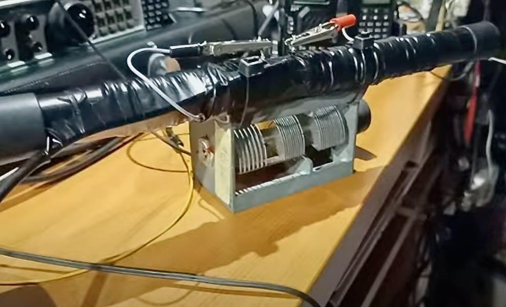
 Many thanks to SWLing Post contributor, Giuseppe Morlè, who writes:
Dear Thomas and SWLingPost Friends,
I’m Giuseppe Morlè iz0gzw,
Many friends have asked for the DICA wiring diagram after my recent post and demonstration.
I’m not a technician but a simple passionate listener and qrp’er… I made this video with a drawing that I hope will be useful to understand the details and how it works…
[Please note that this video is in Italian, but you can use YouTube Closed Captioning; it can even translate the subtitles into English or any other language.]
Thank you all.
Giuseppe iz0gzw.

I wanted to draw the circuit but there is missing detail.
The variable tuning capacitor appears from the video that all 3 sections are connected in parallel so it is one capacitor of around 300 pF. What is not obvious is what the frame of the capacitor connects to.
The winding appears as two coils in series but the far ends are not connected at all. Please use the camera to trace each wire.
Since the telephone cable is a pair of wires, what happens to each end. are the wires connected together to act as a single wire.
In the centre of this series is the input to the radio. What happens if you connect the far ends together?
There will be a big increase in sensitivity would occur if the wire is wound on the ferrite rod itself. Enamelled copper wire is better because you can paint on nail pollish to glue it to the rod. The foam protection can then cover it , followed by the plastic pipe.