
(Image source: Circuit Salad)
Many thanks to SWLing Post contributor, Paul Evans, who writes:
I see this receiver as a remarkable break through. Using audio processor to emulate modes from IQ is very, very clever. This is perhaps the article of the year!:
(Source: Circuit Salad)
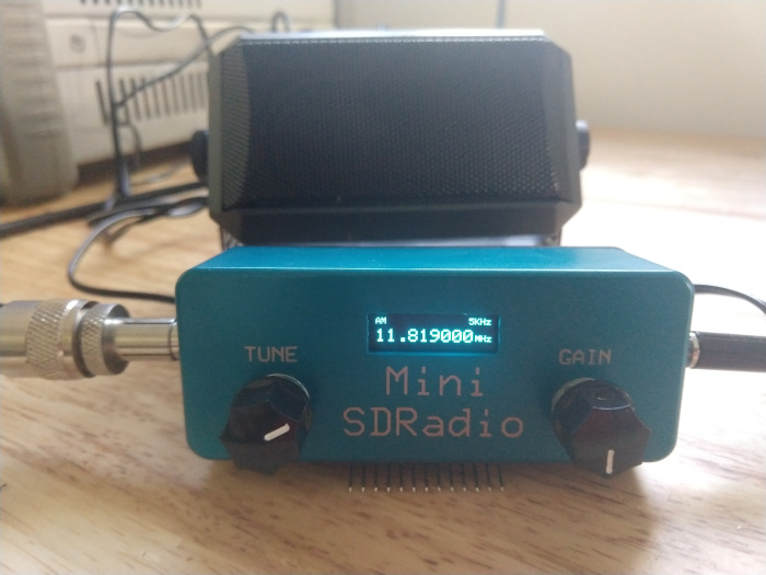
[…]This is a revised version of my FV-1 based SDR. I replaced the CS2100 clk generator with the Si5351 clk generator. The Si5351 has some advantages over the CS2100, namely you can generate quadrature clks directly. This simplifies the hardware design and improves the quadrature accuracy. The sideband rejection in LSB/USB modes is impressive..somewhere around 60 db as best I can measure. The DSP processing is accomplished by the use of a FV-1 audio processor. The device makes the base band signal processing a snap. It requires some code to be loaded on a EEprom but the circuitry is simple and allows for up to 8 selectable programs. I created three: AM/USB/LSB . The FV-1 provides for three analog POT inputs to control any parameters you choose. Gain, variable filter bandwidth and depth, AGC are some examples of adjustable parameters if you desire. I kept it simple and created fixed band pass filters to taste. I did use one of the controls for AF gain. The design has no tuned circuits or band pass filters but they could easily be added. It works just fine without them. Occasionally, I come across a ghost signal from harmonic mixing, when tuning, but not enough to matter. The design uses an OLED display and a rotary encoder for tuning. The frequency coverage is from 2.7 Mhz to 25Mhz. The bottom limit is created by the inability of the Si5351 to support quadrature below this frequency. Although I have improved my DSP programs for the FV-1 and have developed new display drivers and the new code for the Si5351, useful detail about using the Fv-1 can be found in my original design from a few years ago: https://circuitsalad.com/2015/06/19/comming-soon-stand-alone-software-defined-radio-baseband-demodulator-no-computer-required/
The design uses a LTC6252 low noise op amp as an RF input with gain. It provides a constant and reliable resistive Rf termination for the sampling detector. This allows for random antennas to be used without adversely affecting the input termination to the detector. All the code to operate the main processor(display/clk generator/tuning, band select and receive mode) was written in MikroC which is a C compiler for PIC and AVR processors. The generation of quadrature signals out of the Si5351 is not difficult to implement once you know how but..figuring that out took me a couple weeks of experimentation! You can connect switches, the encoder, volume pot and display directly to the main board for operation but I created a secondary board to mount the display and encoders. Instead of an analog pot and selection momentary switches, I used another microcontroller and two encoders(with one built in momentary push switch each) to create all of the switching signals, gain control, etc. This allowed me to have just two controls for all features. The controls include: tuning, audio gain, mode, and tuning step. Tuning resolution is from 1Hz to 100KHz . For fun, I made the output of the FV-1 differential into the audio amp. This is not necessary.
Here is a link to all the files used to build this radio in a zip file(updated 1/18/20):
https://www.adrive.com/public/Fq3pNr/Si5351%20SDR%20Data.zip[…]
Demo video
Wow–that is fascinating! Thanks for sharing, Paul. I’m curious if any SWLing Post readers have experimented with the Si5351.
Interestingly, SWLing Post friend Dave Richards (AA7EE), also recently shared this video of an amazing Si5351-based VFO built by JF3HZB:
This must be one of the best analog emulations I’ve seen on a display. Marry the SDR receiver above to this VFO and you could have a top-shelf homebrewed receiver!
I have put together a list of codes we can use for any homebrew amateur radio project based on SI5351
https://itshamradio.com/amateur-radio-codes-for-si5351
Let me know, if missed anything!
73s
VU3HZW
I had a look at the Si5351A code and do not see how you set the quadrature phase(s) in two outputs. It looks like a more or less standard Si5351A set up routine with just a single output.
Make me one. How much will it cost. [email protected]
I would like to see the source code so I can understand how SDR works. How well is the code commented? How many lines of code?
The source code is available from the full article link. The ‘magic’ – demodulation – all happens in the FV-1 though, which I’m not at all familiar with and appears to have been programmed in it’s own particular assembly language, so is likely to be impenetrable without familiarity with that particular DSP and the assembler’s standard libraries.
But, for a basic overview of IQ demodulation, try this link: https://www.pe0sat.vgnet.nl/sdr/iq-data-explained/
It gets a bit math-y, but if you just accept the maths and continue past it, it shows demonstrates that for simple modulation types like AM and FM you can just treat the “I” component as your traditional time-domain representation i.e. what you’d see on an oscilloscope.
Other modes (e.g. SSB, digital, etc) get trickier…
(Oops, left out an “essentially” there – should read “essentially just treat the “I” component …”. It’s not quite as simple as using the I signal only for AM demodulation, but the AM equivalent signal can be – and sometimes is, at least for demonstration purposes – derived by purely analogue means.)
How many times is this same story going to picked up and rehashed…
The Si5351A has been pretty popular amongst radio experimenters for quite a while (partly because it’s cheap, and party because at one time Silicon Labs were quite generous with their samples policy!). It’s got a few limitations/oddities around the frequencies it can generate concurrently, & programming is a bit convoluted (basically you’ve got a single programmable PLL & 4 programmable dividers, one for each output), but it’s a pretty flexible chip.
The other clever thing – apart from the use of the FV-1 as a generic DSP, which is very clever indeed! – is that, rather than going the usual method of using the Si5351A to generate a single clock at 4*f then dividing it to f with 90 degree phase shifts in the Tayloe mixer, they’re generating the 90 degree phase-shifted signals with the Si5351A itself. I don’t follow SDR homebrew that closely, so until now didn’t know the individual outputs could be controlled/synced that accurately. I’ll have to look at that further…