
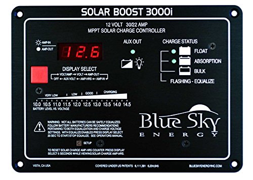
The Solar Boost 3000i solar MPPT charge controller
I’m currently in the process of adding 200-300 watts of 12-volt solar panels to my truck camper.
Solar panels will keep my camper’s 12V deep-cycle battery topped off, thus allowing longer stretches of time for boon-docking or primitive camping, during which an occupied camper is off-grid from shore power.
 My truck camper actually came with a simple built-in charge controller which charges the battery via shore power. Thing is…this shore power charger is incredibly noisy when I’m on the radio. The QRM it generates is broadband, and almost entirely wipes out HF and MW radio listening.
Because of this, I’m forced to unplug my power whenever I’m in the camper and want to hop on the air. And since the whole idea of camper living is to enjoy a bit of rest-and-relaxation, in other words, to pursue one’s hobbies in modest comfort, having to unplug the power––or else not play radio––limits my total enjoyment of RV camping.
But. Before I invest in a new solar charge controller, which would essentially charge the battery any time the sun is out, I need to be absolutely certain it doesn’t create RFI, too. Yet I’m finding it difficult to confirm whether a charge controller is RF-quiet prior to purchasing…
What’s more, I suspect I’m not the only radio listener or ham radio operator with an RV who has encountered the noise dilemma.
What’s a radio geek with an RV to do––?
A ham radio buddy who is an avid RVer recommended the Solar Boost 3000i (see top photo above). While it might be overkill for my application, I’m willing to invest, knowing it may charge without creating RFI.
But before I do, I’m curious if any SWLing Post readers have any experience with solar charge controllers, and/or can confirm models that create little to no RFI? I’d even appreciate knowing which models do pollute the spectrum––models to avoid, in other words, if radio listening or ham radio operations are your goal.
My hope is that SWLing Post reader recommendations may not only help me with this problem, but might help other RVer/off-grid radio enthusiasts, as well.
Many thanks to all of you who have offered suggestions!
In this case, my truck camper is actually in the shop back in the States and I need to order the controller and have it sent to the guy who is doing the install (and a few other upgrades). I’m traveling right now and have no easy way to homebrew or kit build a solution (else I might have considered building another Mike Bryce controller as I think he has a higher wattage version of the Micro M+). 🙂
As long as the new solar charge controller isn’t generating significant RFI, I doubt other sources of RFI will be a problem. At the moment, when the camper isn’t attached to shore power (and the built-in charger isn’t engaged), it’s very RF quiet. I’ll certainly add ferrite chokes to help.
John, I’m leaning toward the Morningstar line. Indeed, I called their tech support and one of the staff called back with a model suggestion that’s pretty affordable. It meets some pretty strict FCC requirement because they’re used in telecom applications where RFI could be an issue. Once I get model numbers, I’ll post here too for others to consider.
Thanks again–and feel free to add to this thread!
Cheers,
Thomas
Whoa, whoa, whoa. I see some compromises here. Doing simple diode reverse flow blocking will get rid of the QRM problem and still maybe sorta charge the batteries, but at a big hit in charging efficiency and shortened battery life, and if they do charge, it is possible to overcharge them. What you have in that photo is a mppt controller which is an efficient down converter that optimizes the output of the solar panel at say 18 to 27 volts and down converts to 12 to 14 volts. It provides charging regulation desulfating and maximum power transfer from solar to batteries as well as My approach would be filtering by grounding and bypassing, put inductive filtering of both input and output. This is a tough problem but solvable. You might want to work closely with the charge controller manufacturer.
Hi
Also consider Ferrite Chokes on Power Cords, Computer Cords, Telephone Cords, etc.. Also no Light Dimmers Flourescent Lights or the new Low Energy light bulbs.
http://www.hamuniverse.com/rfi.html
General RFI-proofing mearures for devices
Install ferrite toroids or ready-made filters on all conductors going into or out of the device. Use higher permeability cores (75 or more) for lower frequencies and medium permeability (43) for 30MHz & up.
Slip a grounded, tubular braid (from some old coax, perhaps) over connecting cords on the device.
Shield the device with a metal box, or wire screening.
Orient the device into a different position or move the antenna on the radio device.
Spray plastic enclosures with an EMI shielding spray to turn them into shielded cases, and ground them.
Finding and selecting ferrite cores
FERRITE MIX
The appropriate ferrite mix to use for HF and below is type 73, 75, and 77 for higher permeability. For VHF/UHF, use type 43.
Here is a source for cores suitable for HF:
Amidon Inc. P.O. Box 25867 Santa Ana, CA 92799 Telephone: (714) 850-4660
Part numbers are: small ferrite bead, number 75 material, FEB-75B-101, $4.50 PK/12
Larger core unit, number 77 material, FB-77-1024, $2.00 EA
Very large core, number 77 material, FT-240-77, $9.00 ea, (great for cables)
From an ARRL Handbook:
Magnetic Properties of Iron Powder Cores
Mix Color Material ? Temp f (MHz) Notes stability (ppm/?C)
26 Yellow/white Hydrogen reduced 75 825 dc – 1 Used for EMI filters and dc chokes
3 Gray Carbonyl HP 35 370 0.05 – 0.50 Stable, good Q for lower freqs
15 Red/white Carbonyl GS6 25 190 0.10 – 2 Excellent stability, good Q
1 Blue Carbonyl C 20 280 0.50 – 5 Similar to Mix-3, but better stability
2 Red Carbonyl E 10 95 2 – 30 High Q material
7 White Carbonyl TH 9 30 3 – 35 Like Mix-2&6, but better temp stability
6 Yellow Carbonyl SF 8 35 10 – 50 V.good Q & temp. stab. for 20-50 MHz
10 Black Powdered iron W 6 150 30 – 100 Good Q and stability for 40 -100mhz
12 Green/white Synthetic oxide 4 170 50 – 200 Good Q, moderate temperature stability
17 Blue/yellow Carbonyl 4 50 40 – 180 Like Mix-12, better temp stability
0 Tan phenolic 1 0 100 – 300 Inductance varies greatly with windings
Radio Shack Ferrites (if you can find them)
There was some discussion of the effectiveness of various ferrite chokes a few days ago. I have access to a HP 4194A Impedance Analyzer, so I put a couple of popular ferrites through a swept-frequency impedance analysis. I measured two of Radio Shack’s products:
the first is a cylindrical ferrite in a plastic holder, about 1.25 inches long by .75 inches in diameter. It opens up like a clamshell and clamps down on the wire. The opening is about 0.25 inches. The values shown are for a single wire through the ferrite. FREQ INDUCTANCE ESR (Equivalent Series Resistance)
300 kHz 2.07 uH 0.073 ohms
2.3 MHz 2.25 uH 6.9 ohms (the inductance peaks at this freq)
10 MHz 1.18 uH 54 ohms
20 MHz 0.80 uH 89 ohms
40 MHz 0.50 uH 130 ohms
The second Radio Shack ferrite is a rectangular device which opens up and allows the ferrite halves to be separated so multiple turns can be wrapped around it. It is 1.675 inches long by 1.125 inches wide by .375 inches thick. The opening is much larger in this ferrite, so more turns can be wrapped around it than the cylindrical one. The values shown are for a single wire through the ferrite. Unlike the cylindrical ferrite, there is no inductance peak.
FREQ INDUCTANCE ESR
300 kHz 0.39 uH 0.044 ohms
2.3 MHz 0.38 uH 0.6 ohms
10 MHz 0.29 uH 7 ohms
20 MHz 0.21 uH 11 ohms
40 MHz 0.18 uH 10 ohms
As with all coils, increasing the number of turns increases the inductance and ESR by the square of the increase. For example, if one turn gives 1 uH and 10 ohms, two turns will give 4 uH and 40 ohms, three turns would give 9 uH and 90 ohms and so on.
One word of caution: Radio Shack is known for changing their product line at the drop of a hat, so use caution in applying these measurements.
One inexpensive source of toroids is to use deflection yoke cores from junk television sets or monitors. They are bulky, even from a small tv, but work well. Multiple passes of the cable are possible to achieve high isolation reactance. These may not have the permeability for the frequency of interest, so experiment.
Making common-mode chokes
The easiest way to make a common-mode choke is to take a ferrite toroid and wrap about 5-15 turns of the feedline onto the toroid, forming a coil. This will attenuate common-mode signals nicely, without significant effect to the differential-mode signals INSIDE the feedline (the desired TV signals in the case of TVI). For lower HF, #73, #75, #77 or J type material is best; for upper HF and VHF, #43 is a good all around material.
To realize effective chokes in few turns it is a need to use materials whose permeability is very high, 2000 or more. Large cable, such as monitor cables, are impractical to wind. The solution here is to use large, split toroids and mate the halves tightly after winding the cable around each half.
“Some improvement” with ferrites indicates that more ferrites added may cure the problem. Radio Shack “Clamp-On Chokes” must have 5 turns or more to be effective on 80 meters. Split beads are about 10 times as good (Palomar FSB-1/2 or equivalent).
Beads must be where leads enter the electronics box. Also treat the power cord and any other wires entering the box. If feasable, .001 mfd disc capacitors from the leads to ground on the box side of the ferrites will make the beads more effective.
This looks like some overkill to me: You must find “the big hole” and not try to desperately close everything that might be a hole.
My idea with the diodes and the short-circuit to avoid overloading the battery has a small penalty storagewise. But besides the power relay it has nothing to produce RFI.
Ferrite is a good idea, but see its limits: Either you put it around every single wire or it will not limit “symmetric” currents.
In the areas where you fear to pick up noise you should use either twisted-pair wiring or coax cable. Everything else might pick up magnetic fields, resulting in symmetric currents – see above. For example use RG-172/U to feed the speaker.
Any “short-circuiting” will ony work if you make the source high-impedance. On RF, you cannot “short-circuit” anything. Any copper braid might be helpful as a protective ground connection. But simply compute the inductance of half a meter od such a conductor.
In my car the transceiver is not connected to the body of the car: Everything going to the transceiver has ferrite on it.
I thought the idea was about a radio friendly charge controller. With one that does not introduce rf interference there is no need to correct problems afterwards. There are some out there.
RFI problems cannot be solved locally: Most RFI propagates wirebound which means that the problems can appear far from the source.
Here is the link to the review that turned me on to the scc3 charge controller kit.
http://www.eham.net/reviews/detail/5586
I built a cirkits scc3 charge controller kit. It is radio rf quiet, easy to order and build and has worked like a charm for my needs. (Off grid, renogy solar panels) I am not an expert but am learning and the kit is simple and works well. Check out this link.
http://www.cirkits.com/scc3/
If you know which end of the soldering iron gets hot there might be a very simple solution:
Lead batteries have a defined maximum loading voltage around 14 V. Standard solar cells provide about 18 V, with the available current varying widely, but the optimum voltage is relatively constant. This leads to something like this:
– For each solar panel put a diode from the plus wire to a plus bar.
– Connect all minus connections together – solar panels, car, batteries.
– Put a diode from the plus bar to the plus pole of the batteries.
– At one battery measure the operating voltage with a smith trigger: It switches in one direction at 14.2 v and in the other direction at 13.0 V or so.
– Get a 12 V power relay that can switch the short-circuit current of your solar panels.
– If the smith trigger is triggered by the 14.2 V, it turns on the relay.
– The power contact of the relay short-circuits the plus bar to minus.
– When the battery voltage vomes down to the lower trigger point the relay drops off.
A few caveats:
– You shound have enough battery capacity that the batteries can cope with the current of the solar panels.
– All batteries should be at least the same technology. Same age and same brand/type might help, too.
– Each diode must be able to carry the maximum current possible. Shottkey diodes might have lower forward drop voltages but have higher reverse currents. The latter might be more important.
– Every wire must be able to carry enough current to trip any fuse connected to it.
– This system does not provide the maximum power imaginable. But invest the money saved with jour homebrewing in another solar cell.
Get a few replacement parts and a 12 V soldering iron and hardly anything can happen while you are off the grid!
Hi Thomas,
I’ve been operating my ham shack for a bit over a year now almost entirely on solar power (the exception being the rare times I use my KPA500). The set-up is two 100W Renogy panels, two 6V T105 golf cart batteries in series and a SunSaver MPPT controller from Morningstar:
https://www.amazon.com/Morningstar-Sunsaver-Charge-Controller-SS-MPPT-15L/dp/B010C45LUM/ref=as_sl_pc_tf_til?tag=inmit01-20&linkCode=w00&linkId=344e5799805e74ed484e645f0864b6b3&creativeASIN=B010C45LUM
The controller is on the same desk as my HF rig, 2 feet away from it, and I’ve never heard (or seen on the pan display) any RFI on any of the ham bands or elsewhere. If RFI were present, I would have gotten rid of the controller long ago. In fact, I bought all this to put on my own travel trailer but it works so well powering the ham shack that I’m going to keep it for that purpose and buy a similar set-up for my trailer.
The one thing I don’t like about this particular controller is that the 3-LED “fuel gauge” always shows FULL even when I purposely deplete the batteries to half their capacity. I exchanged several detailed emails with Morningstar about this, did all the tests & firmware updates they recommended and in the end received an admission from the techs that they had the same issue and that it “may” be corrected in a future firmware update. So far that has not happened and it’s been over a year.
I will buy a different controller for my trailer and take a chance with RFI since ham radio will not be a priority when I’m camping (gasp!).