
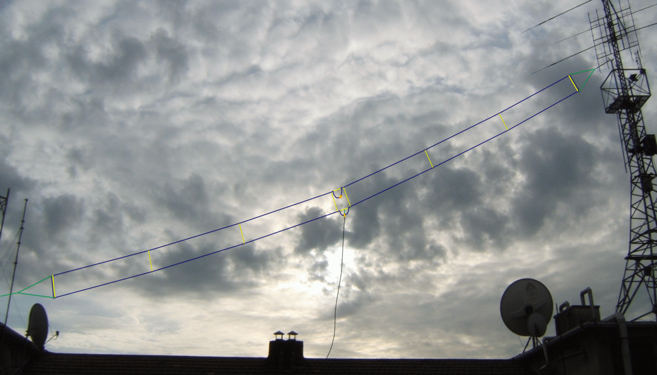
The T2FD Antenna (Source: Wikimedia Commons)
Many thanks to SWLing Post contributor, Grayhat, who has recently been on a mission to create a low-cost SDR setup while sheltering at home due to Covid-19 restrictions. While exploring antennas he sent the following inquiry:
I recently found some information about the so-called Tilted Terminated Folded Dipole (T2FD) antenna which was apparently developed for military use as a wideband, general purpose one (which can mean if it isn’t efficient, simply throw some more KW at it). But for receiving, the antenna didn’t seem bad to me, at least based on the info I found.
In most (if not all) ham installations of the antenna, the T2FD is used in a “vertical” setup–that is, one wire above the other. When looking at military docs, the antenna is in “horizontal” setup, that is, wires parallel to ground. Looking at a 3D lobes simulation of the antenna, the pattern for a “vertical” one seems to be a “cloud warmer” with the most radiating lobe going down toward the feedline. If that’s true, this would mean that an “horizontal” T2FD should have its most pronounced lobe at the feedline side. Perhaps “vertical” installations of the T2FD could go from “works well” to “WOW” just flipping the wires–?
Do you think and SWLing Post readers may have info or experience with the T2FD antenna they could share?
If you have any experience using or building the T2FD antenna, please feel free to comment!
It’s an excellent broadband receive antenna, and a mediocre transmit antenna. If – like me – CW/PSK/MFSK is your thing, then it’s for you. Also the dreaded FT8’ers, who keep all the HF bands including the WARCs ‘warm’ for us.
Don’t expect it to crack DX pile-ups on SSB like a beam, though.
The one in the picture is mine. Was up from 2000 to 2018. It performs just as in the WP article (which I had started), i.e. a nonproblematic general purpose general coverage antenna with no pretense to be high performance and no marked dead spots in the azimut and the frequency domains. Only addedum: I made mine with a small HF-optimized toroid, it unexpectedly turned out perfectly usable to receive down to VLF, where digital broadcasts to submarines are a rock solid 6-15dB above noise.
Well, after modifications to my ‘old’ 70 ft x 28″ wide x 35′ high t2fd , I changed the wire from copper clad steel, to 1/16″ #316 stainless steel. Added an MFJ 915 isolator, at the 50 ohm input of the 16:1 matching xformer.
How did it work? Have made several contacts on 75 mtrs, 60 mtrs, 40 mtrs a bunch, 20, 17, 15. 12 and 10 haven’t tried yet. Signals were normally equal both ways. It’s superior to my old 6 band trap vertical noise wise(which is gone now). NOW I have only one HF antenna, no antenna farm….WA5NTJ
?
Well, ive been ‘experimenting’ with T2FDs for a while. I have a 70 ft long by 24 inch wide one up at 32 ft. With a 16:1 xformer and 800 ohm load. I use it on 75 mtrs regularly, and all other bands up to 10 mtrs. Sooo, that’s it folks…dave Wa5ntj
I’ve built and used several T2FDs from scratch and love them. The simplest was a 6 foot long vertical with a 300 ohm 1/2 watt resistor and a TV coax balun to RG-6 feedline down to a scanner. It was permanently installed inside the wall of an attic in a vinyl sided house and worked surprisingly well. I also built an outdoor 12 foot T2FD with a 325 ohm non-inductive resistor and a homebrew 4:1 balun, again feeding TV coax. The elements were a folded dipole scavenged from a commercial VHF low band antenna. The spacing was mathematically too narrow. I mounted it vertical on the roof and it worked very will from below 6 meters up through military aviation bands. Currently I have an almost horizontal 56 foot long T2FD with a 600 ohm, 50 watt NI resistor and a 9:1 balun. The spacing is 8 inches but mathematically should be around 2 feet. It still works very well for reception, even though it is too narrow and technically the balun is a mismatch. All of these have been very low noise, close to the SN ratios of my active HF loop and way better than dipoles or active E-field antennas. That may be because I use ferrites on both ends of the feedline to decouple induced noise on the coax from the signal inside. My next project is a 25″ T4FD monopole with a 600 ohm, 125 NI resistor. I’m developing on a 12:1 balun on an FT-240-43 core. I’ll be running three spaced wires down the sides of the vertical, which is a modified CB base station antenna. I’m looking forward to the “reduced termination losses, wider bandwidth, and higher radiation efficiency” touted for the T4FD design on the web.
Hi I have been using the Diamond WS-330s 10-meter-long terminated folded dipole for about 2 years and am happy to report it is one of the best antennas I’ve ever used, it lets me pick signals out of the noise that my fan dipole won’t even pick up, it is very low noise, yes some of the signal is lost on both RX and TX but it just works a treat, so much so that I’m going to replace my fan dipole with the 25-meter version.
Phil GW1HNG.
A fellow set up some attached to kiwi sdr web receivers so you can listen to them yourself. https://www.blackcatsystems.com/kiwi.html.
Got here from looking for current sellers (there are several around the world including eBay, but the big ham radio stores in the US don’t normally stock it).
T2(or3, referring to the # of wires)FD is really a terminated loop, which explains how quiet they are. They are related to the Rhombic and Beverage (and probably others I can’t think of right now). There even exists a Terminated Folded Monopole which is just like the regular folded monopole used in MW broadcast but terminated in a way to broaden the bandwidth.
In all cases, a non-inductive resistor (network) is used like a dummy load and a significant amount of power is dissipated in it, unlike a rhombic. This resister acts like a swamping resistor in an active circuit, making the reactance mostly disappear at the cost of lost power. As pointed out above, the users of these things tend to have a lot of power and money to throw at the set up.
Now the big question: besides being quiet on RX, why use this? Because it is super-wide banded, but more physically manageable than a discone, bicone, or relative. Usually its on NVIS circuits or at the most single-hop where the efficiency loss isn’t such a bad thing. The low end band limit is set by the length, as with a normal antenna, though a tuner can force it to work at even lower efficiency (i.e., 160m on a 75m antenna); upper end is where the reactance and pattern get too weird (resistor can no longer swamp it or even becomes reactive itself).
As pointed out, these things are big on ALE, SELCALL, and other systems where tuning is assumed to be near “instant”. They exist solely to remove the need for a tuner / antenna coupler. Another (ham) way to look at it is that it’s the opposite of a slow screwdriver antenna or similar setup where tuning takes multiple seconds, maybe a minute!
Hope this helps!
I used a t2fd in an inverted V configuration with the Apex at 30 feet and worked all states in 2009. Qth was Wichita Kansas. I did have the capability to throw 200 Watts at it when needed.
Ok finally found an answer … and much more at this page
http://hflink.com/antenna/#T2FD
if you scroll down you’ll see a digitized articled dating back to February 1953, written by U.S.N. Capt. G.L. Countryman (W3HH) which offers a lot of details and informations about the T3FD and also explains that the wires orientation makes little difference, placing them side by side makes just easier to deploy the antenna, so my question got an answer, plus the same documents also reports that using a 390 ohm NON INDUCTIVE (IMPORTANT!!) resistor allows to obtain the max gain; in such a case, to feed the antenna with 50 ohm coax we’ll need a 6:1 balun
Thanks everybody for the replies, and I hope that the above link may be useful to others willing to try the T2FD antenna (and NO, if properly built I don’t think it’s a “dummy load”) 😀
I built one a couple of years ago. It was up high and clear, hung between two tall red pines. Testing with an MFJ-259 showed the typical peaks and valleys across the 3 to 30 MHz design range with SWR generally
less than 3:1 everywhere. Receive gain was better above 15 MHz. However it only stayed up for two weeks
as I found it was a terrible noise magnet. I went back to a few traditional dipoles cut for the SWBC bands and
their harmonics. Much better S/N ratio with the dipoles.
Best receive antenna I ever had. A commercial model from Barker @ Williamson covering 5-30 Mhz
and about 60 feet long. A VERY quiet antenna. Even transmitted on it with 10 watts with good results.
A highly recommended antenna for general DX work.
Jeff – VK6FJEF.
Some time ago a fellow OM lent me one he had built himself. He had used it quite successfully hinself. It was such a dummyload that I examined all its components, but could not find an error.
I see no point for a radio amateur to use this antenna type: Within the bandwidth of such an antenna you have a limited number of ham bands. There are lots and lots of antennas for such a combination of bands that are known to work.
For reception I prefer active antennas: Much more wideband and *much* smaller. You can put them in a quiet corner away from the house.
DL4NO, I don’t understand why you’re writing about “limited bands” when a properly set up T2FD will allow one to cover the whole frequency range from the 80 meters up to 10 meters, sure it isn’t “magic” (no antenna is) but if one has limited space, and (say) an OCFD doesn’t fit, a T2FD may represent a way to get the nose out on the lower bands; as for being a “dummy load” I don’t think it is the case, as long as the wire spacing is correct, the loading resistor is a non inductive one and the balun is properly built; again, I believe everyone would like to put up a forest of yagis, OCFD, slopers and then some, but if one doesn’t have enough space and wants to get on air from 80 to 10 meters, the T2FD may be a viable antenna
Andrew,
I currently use a commercially-built T2FD made by B-Squared Engineering in Texas. I use mine for receive only, so bear that in mind. For me, omnidirectionality is of utmost importance and when “tilted” the antenna favors no one direction. It is 45 feet at the high end, and slopes at 30 degrees down to the low end which is about 7 or 8 feet above ground . It is 122 feet long, which allows excellent coverage from 30 MHz down to around the lower portion of the MW broadcast band. Below 500 kHz or so, reception rapidly degrades. For LW reception, I use an tuned, outdoor-mounted e-field antenna, which works quite nicely.
If you don’t have the room for 122 feet, shorter lengths will work. The length of the T2FD is dependent on the lowest frequency of interest, so keep that in mind. The orientation of the two parallel wires (with respect to the plane of the ground is NOT critical, for receiving. I tried both and I could find no discernible advantage from having one over the other. Keep in mind that having the antenna tilted at roughly 20 to 40 degrees as it slopes from your highest end to your lowest end makes the antenna omnidirectional and and quiet from man-made noise from home devices.
Compared to an end-fed inverted L of comparable length I have used in the past, the T2FD is noticeably quieter with respect to man-made noise. Omnidirectionality is the same. Signal levels are higher with the inverted L, but the signal-to-noise ratio suffers considerably.
In conclusion, in today’s sea of man-made noises, the T2FD is a winner.
Hi Andrew… In the early 1990s I used T2FDs extensively, and wrote an article for the popular book series “Fine Tuning’s Proceedings” about this antenna. Perhaps this piece will give you some useful information. I’ve extracted this early 1990s article from the Proceeding archive and have posted it separately on Box.com:
https://app.box.com/s/au3kxukzk5znqzyi3vqrnjvxxcomy81h
The article references some earlier publications too in case you want to research the T2FD further.
73, Guy
Hi Guy, first of all, thank you for the reply and for the document (and for writing it !); while searching for informations about the T2FD I also found a partial copy of that document and was interesting but the copy you posted is far more complete
Pity there’ s no info about the difference (if any) made by the way of laying out the wires … oh well, will keep searching and at worst I’ll run some raw tests myself
Just a note, the loading resistor value should be around 15% higher of the desired feedpoint impedance, not a precise calculation but that’s what I found while seeking for infos
Also, while the T2FD isn’t a super efficient TX antenna, since up to 30% of the TX power may be dissipated by the resistor, I believe it may still be a good antenna for people willing to cover most/ all ham bands and having restricted space, plus is a quiet antenna in RX which by the way is a good thing
I had a T2FD at the old house. Receive only and agree with CX2AD…..very very “quiet” antenna.
I used a T2FD for several years from 1998-2001. Was relatively easy to build-not so easy to erect given I had to string above a neighbors house, but they gave me permission. Cannot remember the exact dimensions of mine but I had the perfect setup with two large trees to serve as supports at either end. I found it to be relatively quiet for reception. Used a FRG-7700, Sony 2010, and a AOR-3030. Worked well with all. Made some very fine DX catches from my QTH.
I had the RF Systems T2FD back about 30 years ago, and it was mostly great antenna, with one big exception, it didn’t last too long, 5 years I think it was all it made it. Every winter, it would ice up during a storm and need some repairs, and I kept trying to improve it’s durability. It finally came down for good in a big ice storm and I didn’t put it back up. But while it was up, it was very quiet, and was the most usable antenna of the 3 main antennas I had up back then, most of the time. The Slinky ruled over all under 5 Mhz.
The other two were a very large slinky dipole that sloped from the top of my TV tower (40 feet) to a plastic pipe topped with a 90 degree elbow and a plug with an eyebolt through the plug. The flex of the pipe kept the rope snug and that antenna lasted about 20 years. The third antenna was an Alpha Delta short sloper, which worked well too, and since I waterproofed it to an extreme measure, it lasted over 25 years and only came down when I moved out of the house. Other antennas were a “Big Stick” CB antenna, and a dipole in my attic. With the exception of CB, 10M, and VHF low, any of the 3 main antennas worked better than the Stick or the dipole.
Oops, I forgot, I had the wires side by side for almost the entire time and saw little difference when I put them vertical.
Hi Andrew
Cannot help in this matter. Suggest to build a small prototype, even indoors and try both configurations. And also help us with your observations.
Wal
Thank you all, but the point is understanding if and how, laying up the two wires horizontally or vertically (with respect to ground) changes the T2FD radiation pattern; on most if not all ham sites, the antenna is shown in vertical setup, but looking at pics of mil or similar services (coast guard, airports, …) the same antenna is horizontal, so … what’s the difference ?
As far as I can tell, in horizontal setup (wires parallel at same height from ground) the antenna may act like a “rhombic” that is become somewhat directive, but mine is just a guess, so … does anyone have infos ?
Andrew (aka grayhat)
Barker & Williamson is offering complete antennas and parts. Some military suppliers mostly in Europe too. DX Engineering Yaesu YA-30. Check Palomar Engineers
RF Systems once offered such an antenna for receiving:
https://www.universal-radio.com/catalog/sw_ant/0562.html
Discontinued loong ago, however.
Hi Grayhat.
In 2003 I’ve decided to build a T2FD. The size is about 85 ft. in length and 3 ft. wide. I used solid copper wire AWG 9. Is in an inverted vee configuration roughly pointing 340-160 degrees (Location GF15VD28KX) with the top center apex at 43 ft. and both ends at 20 ft. tops) I’ve used 2 and a half lengths of 20 ft. long thick wall water pipes for the center mast filled with wood poles to avoid sagging. Supports wires are with UV plastic fence wire. For the balun and terminating resistor I scrapped whatever I had, namely a bunch of carbon resistors soldered in series-parallel to reach a value of about 500 ohms and a home made balun with a T200-2 in a 9:1 configuration.
In those days I had a Kenwood TS-830S with a AT-230 manual tuner. As a former Merchant Marine Radio Officer, I like SWL, so I also had a Furuno RV108S marine receiver. Soon after I moved to Europe until 2009 thence to Argentina.
I cannot provide technical data of the antenna performance, just tell on-the-air experience. First if you build all the elements yourself take the utmost care in sealing. Water find a way to seep inside the boxes. The antenna is still standing after 18 years and when I go to see my family in Montevideo, I use the same to do SWL, now with a portable SDRplay RSPduo (I have now a Kenwood TS590SG but will bring it back to Uruguay when retiring). I reception is extremely quiet and am quite happy that still able to do some good DX catches even in the SW Tropical Bands. Take into account that we are still at the deep of the solar cycle. Long gone are the days when wherever you tuned it was bursting with signals. As you go up the bands 15 meters Ham and 25 meters Broadcasting it begins to lose reception properties but never is a deaf antenna. As regard with TX I had very little experience but for a 2-30 MHz antenna the few contacts I did were quite satisfactory. Guess is a trial and error building process. Suggest you use separators between the top and lower wires, I didn’t and experience uneven sagging so every time I go, must do some adjustments in tension. Use RG-213 or better even if in low power. There are some manufacturers and dealers in the US where you can purchase the balun and terminating resistor.
Overall qualification is Excellent and very, very quiet. Your mileage may vary. There is no scientific formula that will ensure a perfect antenna, is just empirical. Go ahead and experiment. When solar cycle improves, I am sure your rig will jump out of the table with signals. Hope this useful. Take care and stay inside.
73
Wal / CX2AD