Category Archives: Antennas

Bob’s Radio Corner: Which Antenna Input is Better? – A Case Study

By Bob Colegrove

A DXer recently posted the following question on the Internet: “Why do I get a much stronger signal if I clip a long wire to the telescoping antenna than if I connect it to the external jack”? He then postulated that this might be due to different input impedances at each point. Different receiver input impedances could affect the performance of a long wire antenna at a specific frequency.

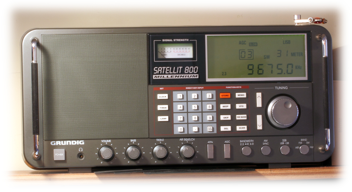
The question reminded me of an experience I had a few years ago with both the Grundig Satellit 750 and 800. Different radios than that in question, but the same results. What follows describes a little-known feature I stumbled across (no claim to discovery) on the Satellit 750. Later, when I got a Satellit 800, I found it also worked on the older big brother.

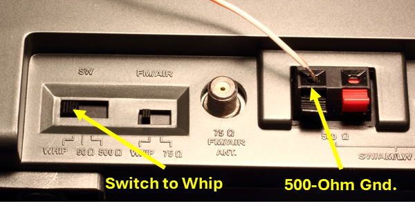
The 750 and 800 radios share similar appearances and many of the same features, among them the various antenna input options, including a 50-ohm SO-239 for LW, MW, and SW; a 500-ohm pair of compression clamps for long wires when tuning the same bands; an F-connector for VHF; and a lengthy whip antenna which can be used on any band. Input selections are made with a pair of switches adjacent to the terminals on the back or side of the radio.

To mitigate noise, I use resonant loops to the exclusion of almost everything else. Just for fun, I tried the whip antenna as an input for a loop. Understand that the whip is a single-pole, electric field probe. There is no accompanying ground, or, as it is more euphemistically termed these days, a “counterpoise.” Thus, for application of a dipole or loop antenna, one must find a counterpoise. This was easier than expected, as it turned out to be the otherwise unused compression ground terminal for the 500-ohm input. When coupling antennas on radios, it does not always have to be invasive. I managed to temporarily jury-rig the connections to the loop antenna. The receiver came alive.

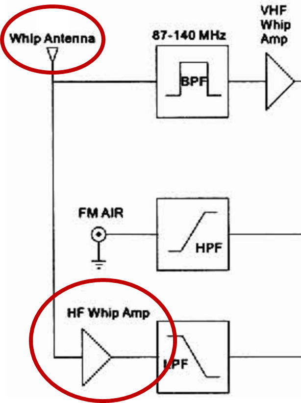
What’s going on here? A check of the block diagram and schematic provided the answer. The circuit for the radio’s whip antenna input contains an additional RF amplifier stage, which is not used for either the 50- or 500-Ohm external antenna inputs.

For anyone interested, the easiest download for the block diagram (Sheet 2) and RF schematic (Sheet 4) is at https://elektrotanya.com/grundig_satellit-800_sch.pdf/download.html#dl. These drawings are labeled for the Chinese Ham-2000 branding of the Satellit 800 and are fuzzy but readable.

Besides this subtle suggestion, the only other clue I have been able to find for this circuit came from the review in the 2002 edition of Passport to World Band Radio. “Weak-signal shortwave sensitivity with an external antenna can be boosted by setting antenna switch to ‘whip,’ thus adding preamplification…” (p.129); [sic] and using the whip for the input.

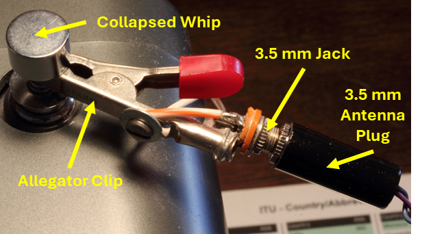
The effort soon became one of rendering the connection between the loop (or any dipole) antenna and the receiver more permanent. There was a time when I might have violated the integrity of the radio and done a proper job of it. A proper job would be to completely bypass any potential unshielded source of RF, in this case, the whip itself, and connect a shielded lead-in directly to the amplifier. At this point I didn’t want to make any permanent alterations to an otherwise museum-quality unit. Truth be told, I’ve grown averse to exertion of any unnecessary effort. The result is certainly not elegant. Further, the lack of shielding around the exposed whip might potentially compromise the results. Nevertheless, the kluge pictured below was fabricated and works surprisingly well, maintaining normal peak and null responses from the loop.

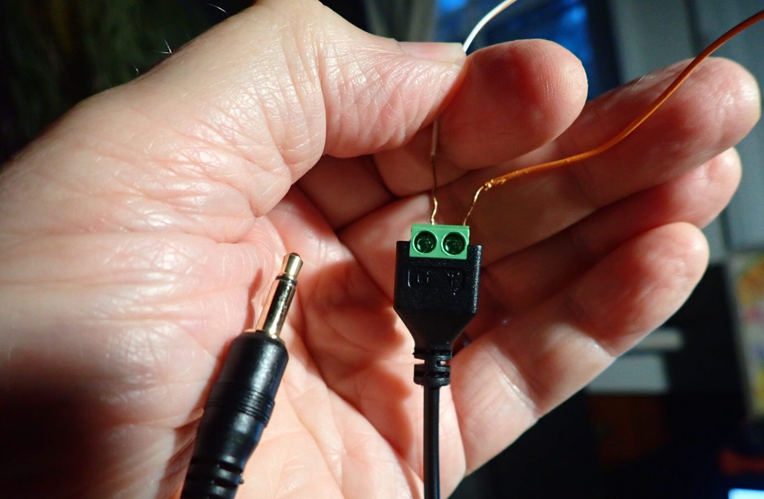
The ”hot” terminal of a 3.5-mm jack, compatible with the plugs on my antennas, has been soldered to an alligator clip, which, in turn, is connected to the top of the collapsed whip antenna on the radio. The “counterpoise” is a short piece of hookup wire connected between the ground lug on the 3.5-mm jack and the grounded compression terminal on the radio. Without a counterpoise for a loop or dipole, it will simply act as an electric field extension of the whip. The only other requirement is to set the “SW” switch (also used for LW and MW) to the “WHIP” position.

If you’re working with a long wire (monopole), forget all that stuff above, and just clip the wire to the top of the whip. I will add a caution about connecting long wires. Semiconductors are vulnerable to high voltage input. Electrostatic discharge, either atmospheric or bodily, has been known to ruin input circuits. Fortunately, this does not appear to be a problem in recent years, and the external wire packed with your radio is likely quite safe for experimentation.

I am not a big fan of active antennas, feeling they are often a source of additional noise. However, in the case of this little deviation from the normal antenna inputs on these radios, the amp is already there, and the result has been very satisfying, proving once again that a bit of tinkering in this pastime is sometimes advantageous. Note: For many portable radios, the whip input does not work on LW and MW, so this approach will only apply to SW.

If there is a point to this posting, it is in the form of a question: Are there any other radios having one of their inputs augmented (amplified) – likely the whip? The fact that a radio is equipped with a whip antenna indicates that, by design, it is intended to be portable. For LW, MW and SW, this means whip antennas pose an acceptable operational handicap. This compromise permits the listener some flexibility to move around with the radio. So, it’s reasonable that designers may have chosen to augment the whip with some internal amplification.

Finally, don’t give up on an antenna input which appears to be less sensitive. It may be more responsive on a different band, or it may mitigate overload produced by the hotter input. Whether it’s a case of different input impedances or an extra RF amplifier inserted on the whip, it’s in a DXer’s interest to find out if performance differs for each input on their own radio.

Don Pushes Portable Antennas Further: Loop Size, Performance, and Real-World Limits (Part 2)

Many thanks to SWLing Post contributor Don Moore–noted author, traveler, and DXer–who shares the following post:


Two Portable Antennas for Remote DXing (Part Two)

By Don Moore

Don’s traveling DX stories can be found in his book Tales of a Vagabond DXer [SWLing Post affiliate link]. If you’ve already read his book and enjoyed it, do Don a favor and leave a review on Amazon.

In my initial comparison of the PA0RDT mini-whip and the MLA-30+ MegaLoop, the mini-whip performed best on medium wave and the lower shortwave bands, while the loop worked better on the higher bands. But, I wondered, why should the MLA-30+ be restricted to that small steel loop? The wire loops I use with my Wellbrook ALA-100LN typically range from twenty to fifty meters in circumference.

I threw a twenty-five-meter wire over a tree branch and formed it into a delta with the MLA-30+ in the bottom center. Remember, I was testing in the northern Chicago suburbs. My SDRs were completely overloaded. Medium wave was useless and I had strong MW stations all over the shortwave bands. The MLA-30+ doesn’t have the same strong-signal handling capabilities as the Wellbrook. And there are a lot of strong medium wave signals in the Chicago suburbs.

So I took that wire down and replaced it with a loop of twelve meters circumference.

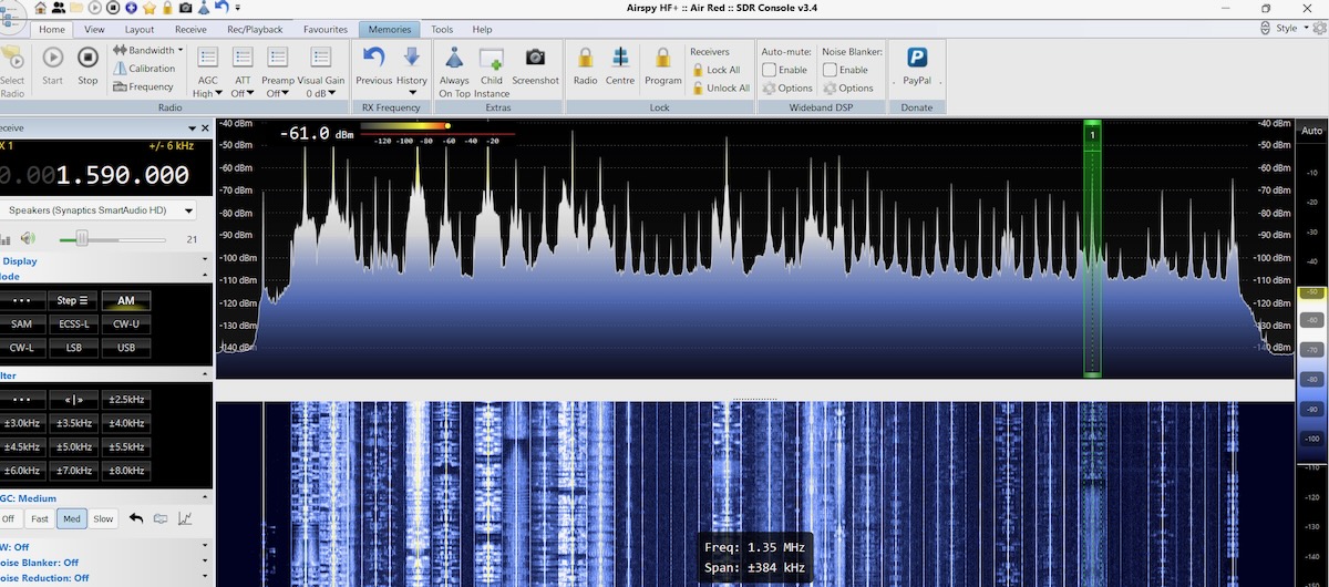
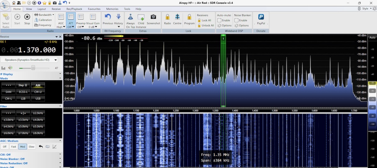
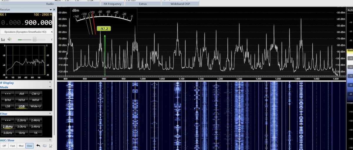
That did the trick. I had lots of signals on medium wave without the overloading. Here’s what the upper end of the MW band now looked like with the MLA-30+.

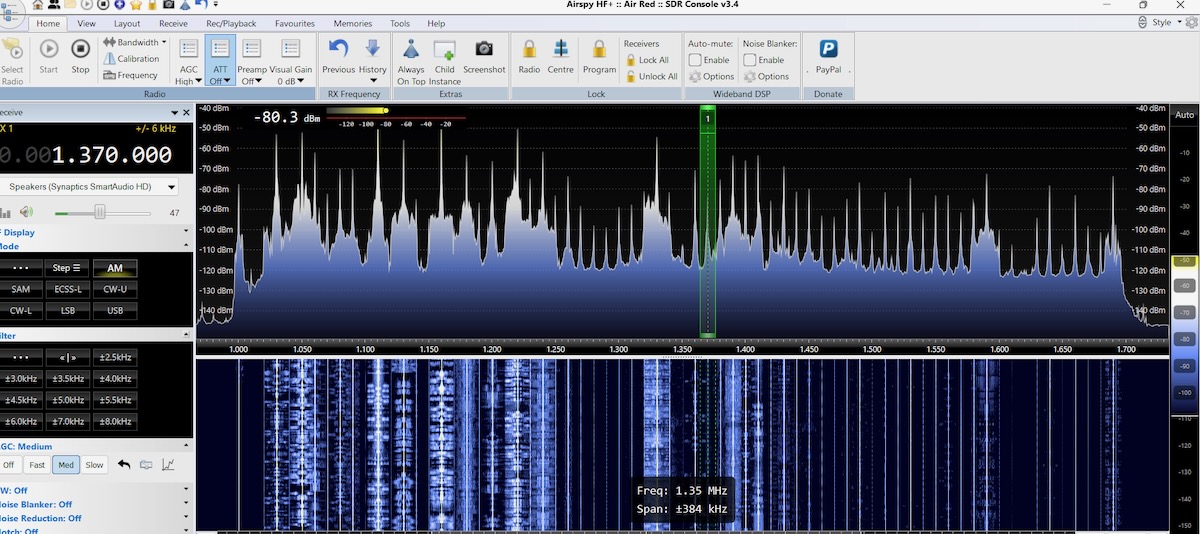
For comparison, here’s the same wire loop using the Wellbrook ALA-100LN. The Wellbrook has a slightly lower noise floor but otherwise the signals are about the same.

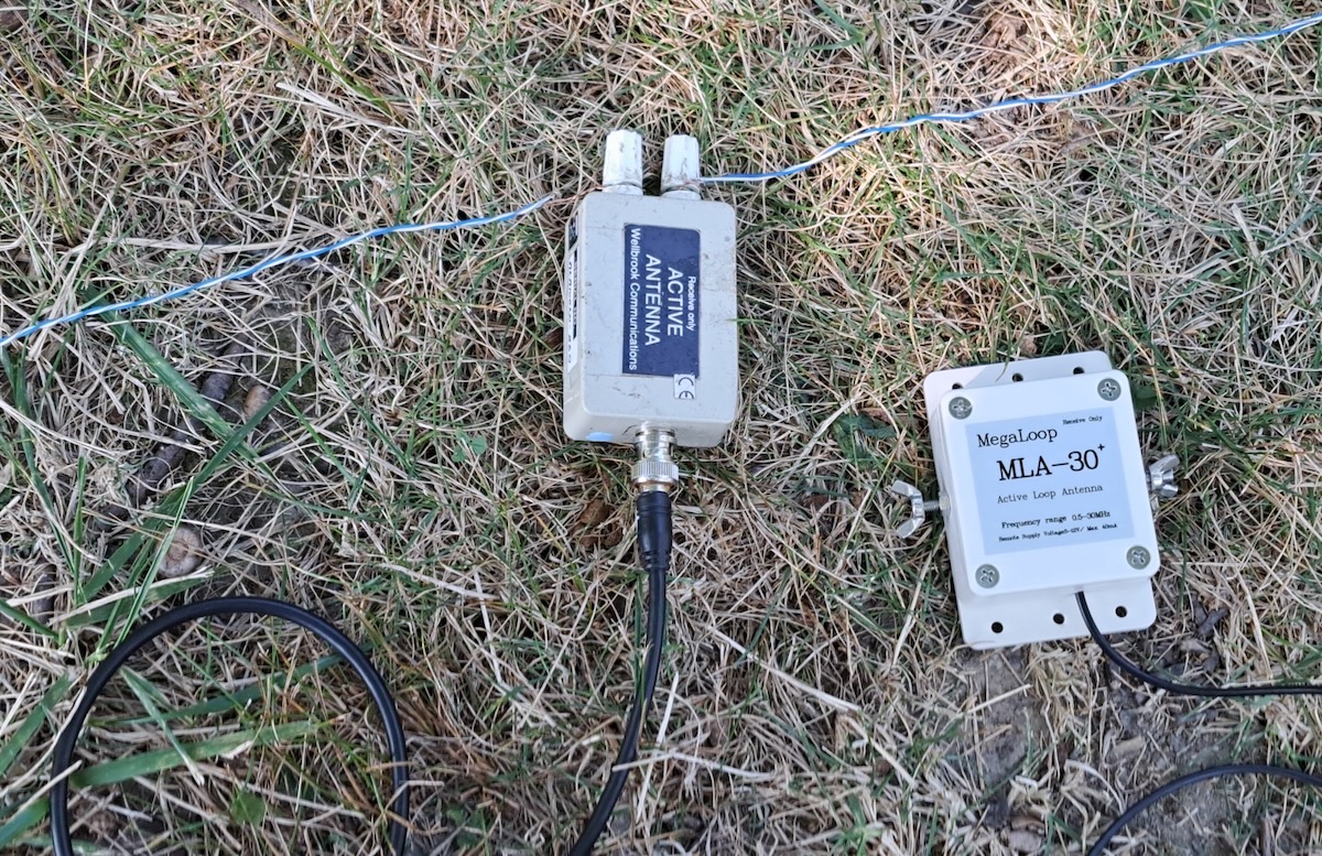
Out of curiosity, I replaced the Wellbrook power unit with the Bias-T from the MLA-30+ but left the Wellbrook antenna head unit in place. With this hybrid setup there’s no visible difference with the full Wellbrook.

I was satisfied with my findings but I still wondered how much wire the MLA-30+ could handle. A few weeks later I ran some more tests in Kansas, where I knew the dial wouldn’t be as crowded. The MLA-30+ easily handled a 25-meter delta loop without overloading.

Two weeks after doing the Kansas tests I was at a DXpedition in rural western Pennsylvania. The MLA-30+ worked fine with a 40-meter circumference loop, other than being a tad noisier than the Wellbrook with the same wire. So how much wire you can use with the MLA-30+ components depends on how strong your local medium wave stations are.

Findings

From the SDR images above it would be easy to conclude that with the right length of wire an MLA-30+ is just as good as a Wellbrook ALA-100LN even though it is significantly cheaper. But that’s not the full picture. Back in the 1990s my Drake R-8 cost about three times what my Sony ICF-2010 did.  All other things being equal, I would say that 95% of the DX heard on the Drake could have been heard equally well on the Sony. I wanted the Drake for the other five percent.

I have no doubt that if I did a very careful head-to-head comparison of the two units under serious DX conditions on the same wire that the Wellbrook would get things the MLA-30+ couldn’t. But I suspect the difference would be around that five percent mark. I’m willing to accept that tradeoff for an effective cheap light-weight travel antenna. And the MLA-30+ is like having two antennas in one. I can use it with the steel loop in limited space situations or with a larger wire loop when I have access to some garden space with a tree. Together, the MLA-30+ and the PA0RDT make the perfect DX travel antennas.

The only thing I didn’t like about the MLA-30+ was that pre-attached coax cable. It’s not the best quality and I’d rather carry my own cable. I’m not very handy with a soldering iron in tight spaces but at our recent DXpedition my friend Bill Nollman replaced the coax with a BNC jack for me.

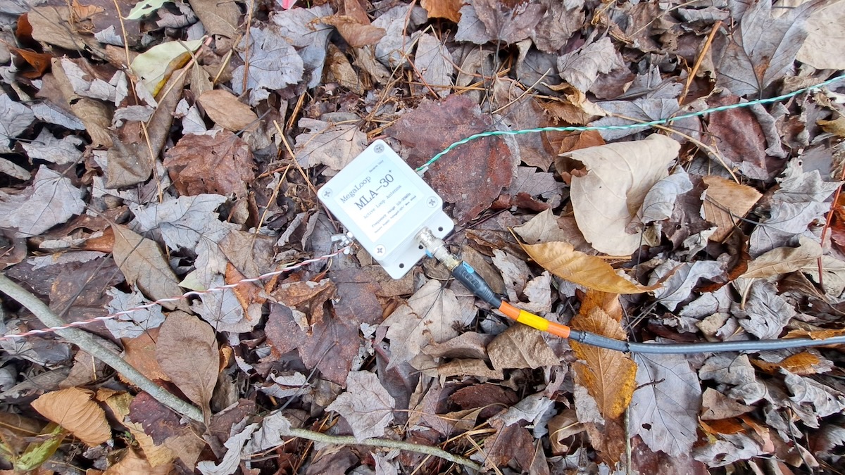
The MLA-30+ now looks like this when connected to a wire loop.

Finally, I should address powering the MLA-30+ via USB. While it can be connected to a spare USB port on your laptop, I found doing that sometimes introduced a tad more noise. Instead I’ve been using one of those battery packs used for recharging cellphones. Mine is rated at 6700 mAh and it can power the MLA-30+ for over 48 hours before needing a recharge. But be sure to test yours before doing any serious DXing. I’ve read that some power packs have a minimum required power draw and will automatically shut off if the draw is too low.

Another Option?

While I was finishing this article I heard about another option from my friend Guy Atkins.  This antenna is a combination of the YouLoop with a low-priced Chinese made clone of the LZ1AQ amplifier. Some users say it’s better than the MLA-30+. Guy says it works well on shortwave up to 16 meters but he hasn’t tried it on medium wave. Guy says it’s a “low price, good value” antenna. I’m traveling in Southeast Asia for the winter but will definitely have to try this antenna when I get back to the USA. So maybe there will be a follow-up article next summer.

Links

[Note: Amazon links are affiliate and support the SWLing Post at no cost to you.]

Info on ordering a quality PA0RDT from Roelof Bakker. (Other cheaper versions have had issues with quality control.)

https://dl1dbc.net/SAQ/miniwhip.html

There are various versions of the MLA-30+ and the original MLA-30. This is the version that Mark Taylor recommended and that I bought.

https://amzn.to/3MEKjPY

There are numerous YouTube videos on using and modifying both versions of the MLA-30+. This one shows how to replace the coax with a BNC jack.

https://www.youtube.com/watch?v=OAqh2Lawwdc

Here’s the Amazon link for the YouLoop/LZ1AQ antenna that Guy has.

https://amzn.to/4s1RB09

And the same antenna on Ali Express.

https://www.aliexpress.us/item/3256808527623276.html

Portable Antennas for Serious DXing: Don’s Field Tests from Parks to the Open Road (Part 1)

Many thanks to SWLing Post contributor Don Moore–noted author, traveler, and DXer–who shares the following post:


Two Portable Antennas for Remote DXing (Part One)

By Don Moore

Don’s traveling DX stories can be found in his book Tales of a Vagabond DXer [SWLing Post affiliate link]. If you’ve already read his book and enjoyed it, do Don a favor and leave a review on Amazon.

Once upon a time, I had a traditional DX shack with an L-shaped desk and shelves of receivers, radio gadgets, and DX books. Everything I wanted or needed as a DXer was right at hand. Then I retired and was finally able to pursue my lifelong itch for serious travel. But there was no way to carry that DX shack along with me. Fortunately, modern technology was there to help. SDRs are significantly more travel-friendly than my old Sony ICF-2010 (let alone the Drake R-8). Instead of books and bulletins, my DX reference materials are websites and PDF files on my laptop.

I spend several months a year traveling internationally with just a suitcase and knapsack. That doesn’t leave much room for DX equipment. Several years ago I described my approach to vagabond DXing in an article here.

https://swling.com/blog/2019/03/radio-travel-a-complete-sdr-station-for-superb-portable-dxing/

Since writing that article in 2019, I’ve continued to work on making my portable DX shack better and more compact. Recently, I replaced the Elad FDM-S2 with three Airspy HF+ Discovery SDRs. Not only are they smaller and lighter, but I can record three different band segments at once. Next up was rethinking my travel antennas. A wire loop with the Wellbrook ALA-100LN is still, in my opinion, the best travel antenna. But the components are heavy and are now irreplaceable since they are no longer made. So over the summer, I set about testing and comparing both old and new options. But you don’t have to wander the globe for my findings to be useful to you. This can be just as helpful for DXing from a nearby park. That’s how I did my testing.

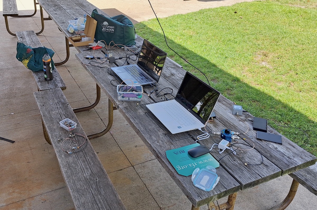
I spent the past summer staying at an AirBnB in the north Chicago suburbs. I wanted a better location for testing so I checked out parks in the area and finally settled on Preserve Shelter B (42.26797, -87.92208) at the Old School Forest Preserve, east of Libertyville in northern Illinois. The shelter was entirely wood, with standard asphalt shingles (rather than steel), and had no nearby power lines. I made four daytime DXpeditions there to do some utility DXing and to run my tests. Here’s a photo of my setup.
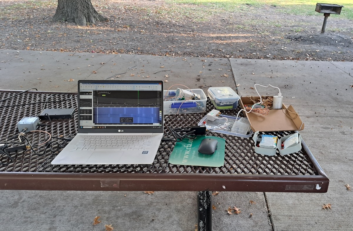
I decided I should rerun the tests at least one other location. So while driving across the US in mid-October, I stopped for a few hours one morning at Park Shelter A (39.11144, -94.86629) in Wyandotte County Park, just west of Kansas City, Kansas. There, I just had a minimum setup.
The Antennas

So, what were the antennas I was testing? The first was the tried-and-true PA0RDT mini-whip from Roelof Bakker. The PA0RDT is described in my 2019 article and is probably the most portable quality antenna you can get. To power it I use a battery box and eight rechargeable lithium-ion AA cells.
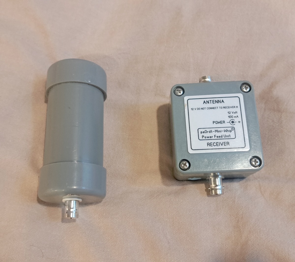
 For the traveling DXer, setting up the PA0RDT is as easy as it comes. I just attach the coax cable and throw it over a support, such as a picnic shelter beam or a tree branch.
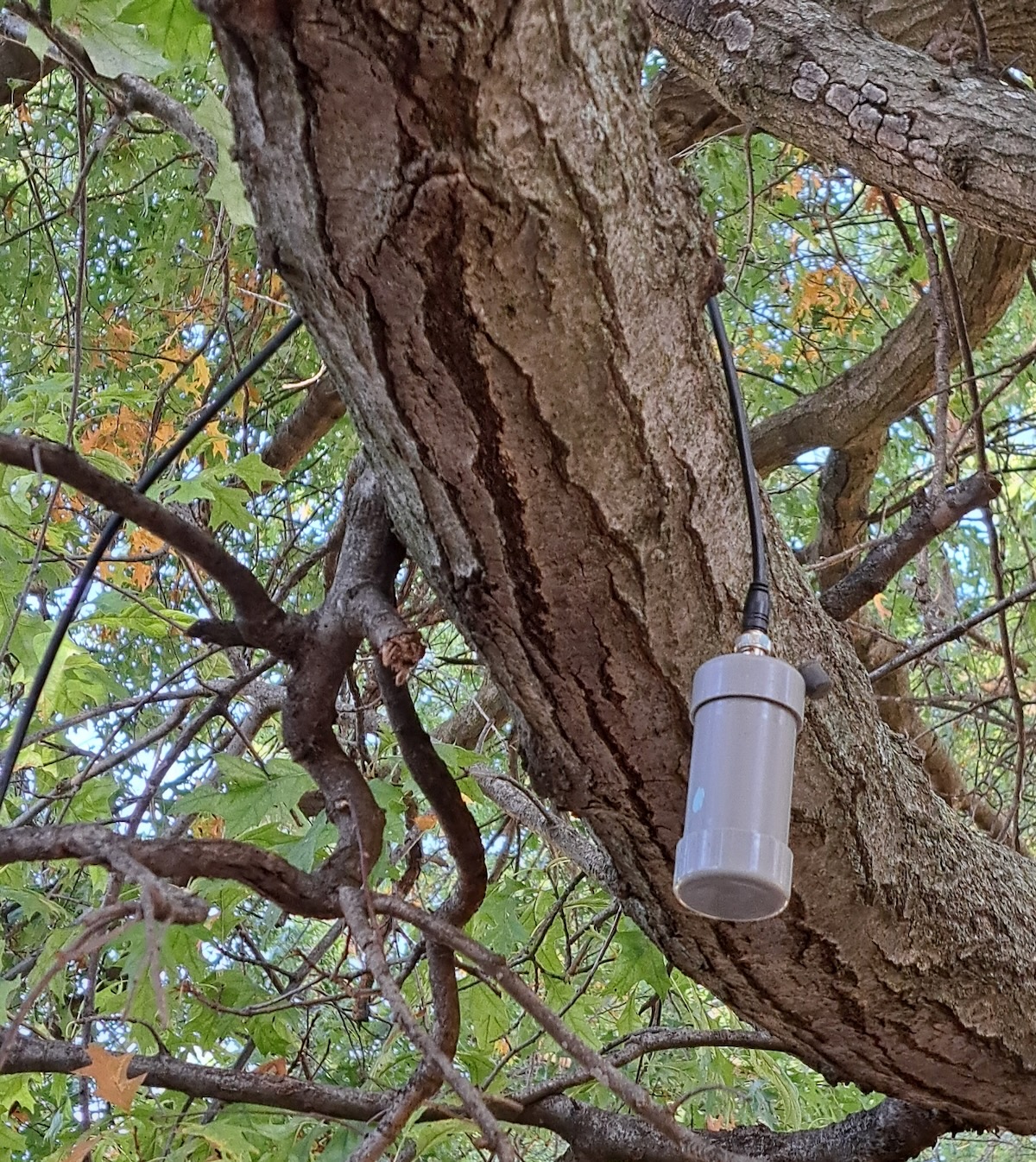
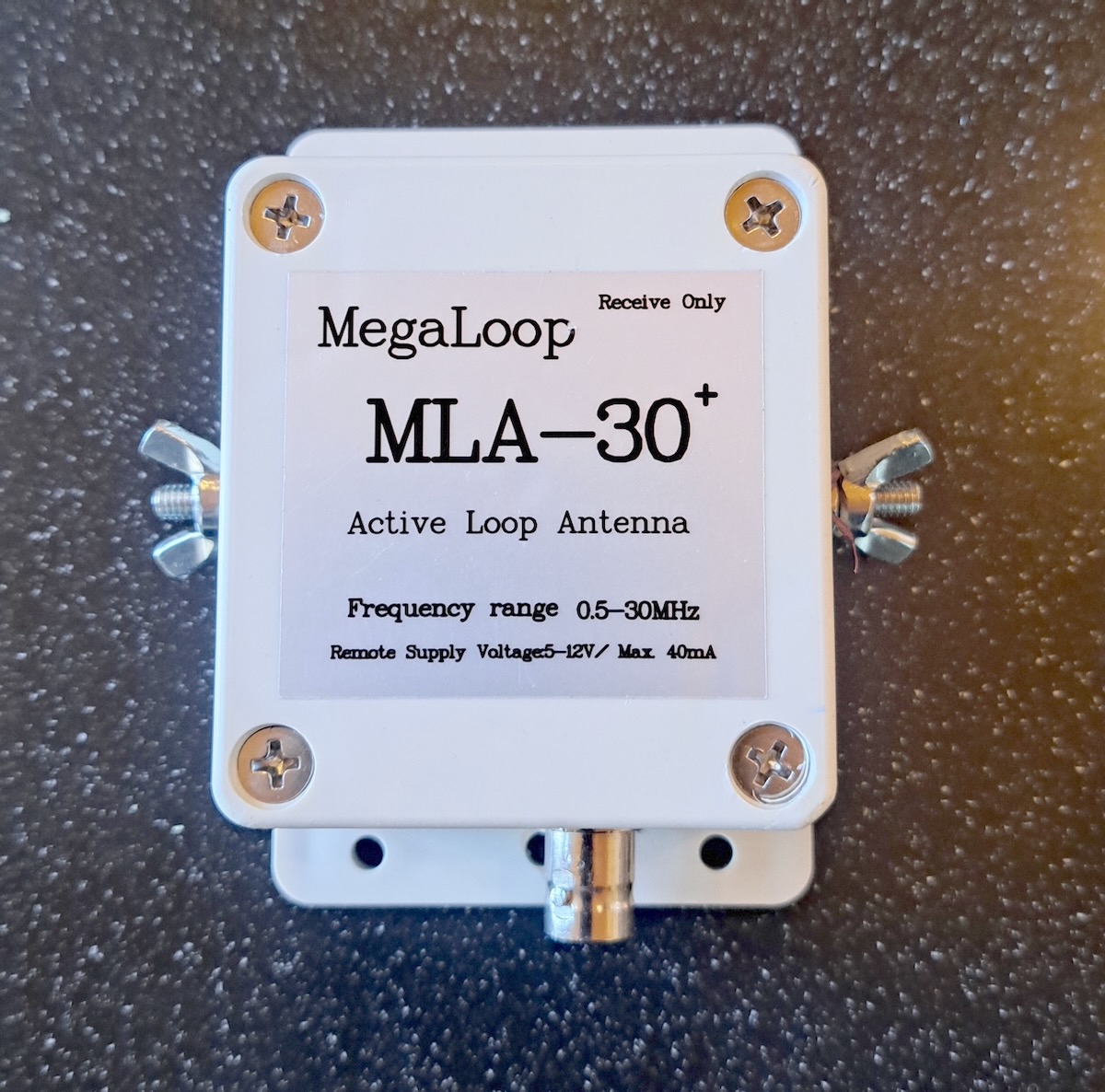
But I’ve always believed that the best antenna is another antenna. That is, every antenna works differently, and therefore the more options you have, the more likely you will have something that works well in any situation. So if I wanted to leave the Wellbrook at home, what might complement the PA0RDT? I contacted my friend Mark Taylor, who I knew had a large collection of the various inexpensive Chinese-made amplified loops. With his help, I settled on the MLA-30+ MegaLoop from DmgicPro.
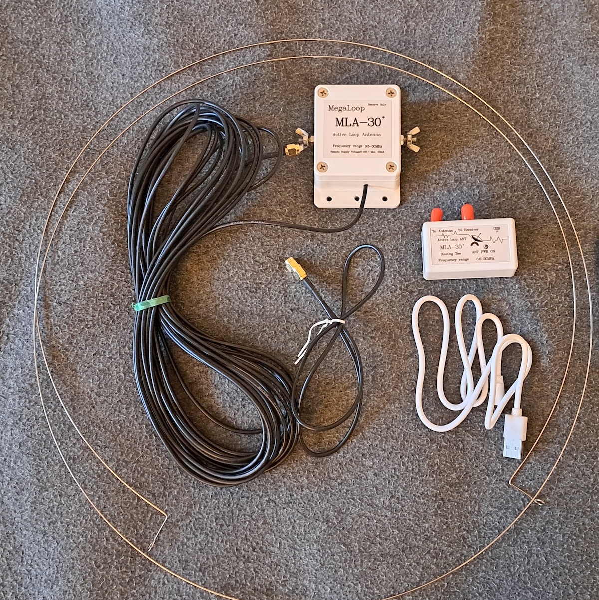
This antenna consists of a steel wire loop that connects to terminals on the amplifier box. The amplifier has a ten-meter coax cable, which in turn is connected to a small bias-T power supply, which gets its power via a USB connection. The MLA-30+ is designed to be used in a permanent installation with some sort of vertical support, such as a PVC pipe. Some users replace the wire loop with copper tubing.

Those options aren’t practical for me, and simply hanging the antenna from the top would cause the steel loop to stretch and deform. So I came up with the idea of tying a strong cord from the top to the bottom of the loop so that the cord, and not the loop, bears the weight. To hang the antenna, I throw the cord over the support, attach the antenna, and then pull it up into place. That works well if you have rear support to hold it in place, such as the beams of a picnic shelter.
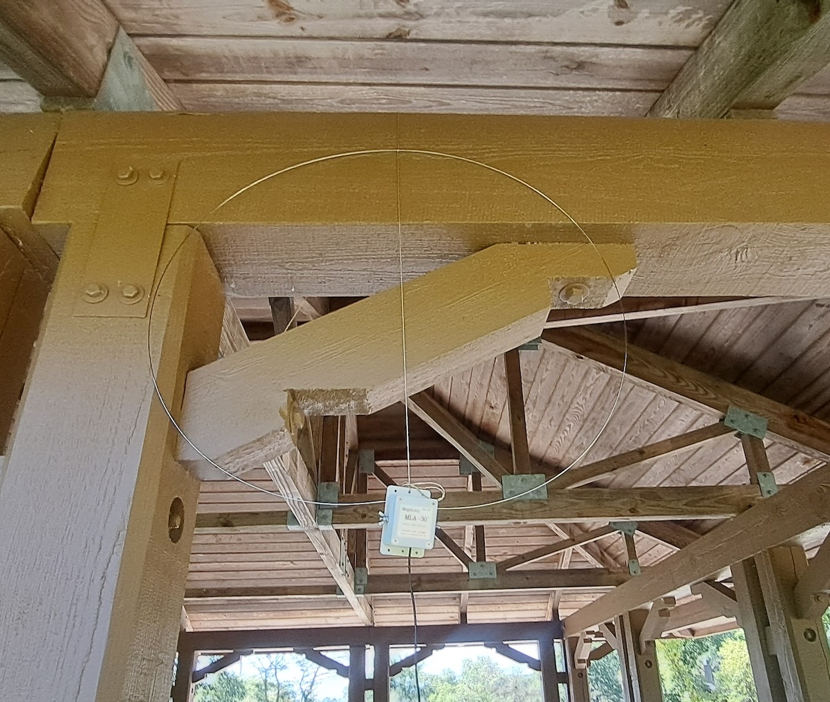
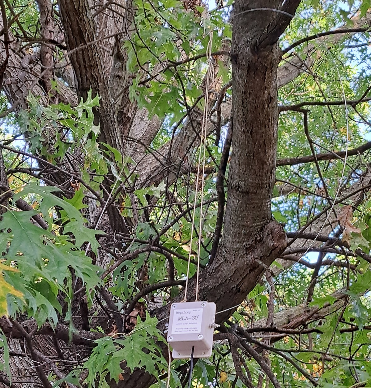
It’s a bit more difficult to mount the MLA-30+ in a tree.
Comparing the Antennas

I ran comparisons between the antennas several times at Old School Forest Preserve and then again at Wyandotte County Park. The results were practically the same every time. The images below were made at Old School unless otherwise stated.

The PA0RDT was designed to be a good performer on longwave and medium wave. Unsurprisingly, it shows a lot of signals on the upper end of the medium wave band, even during the daytime. Except for being non-directional, the PA0RDT is an excellent MW antenna.
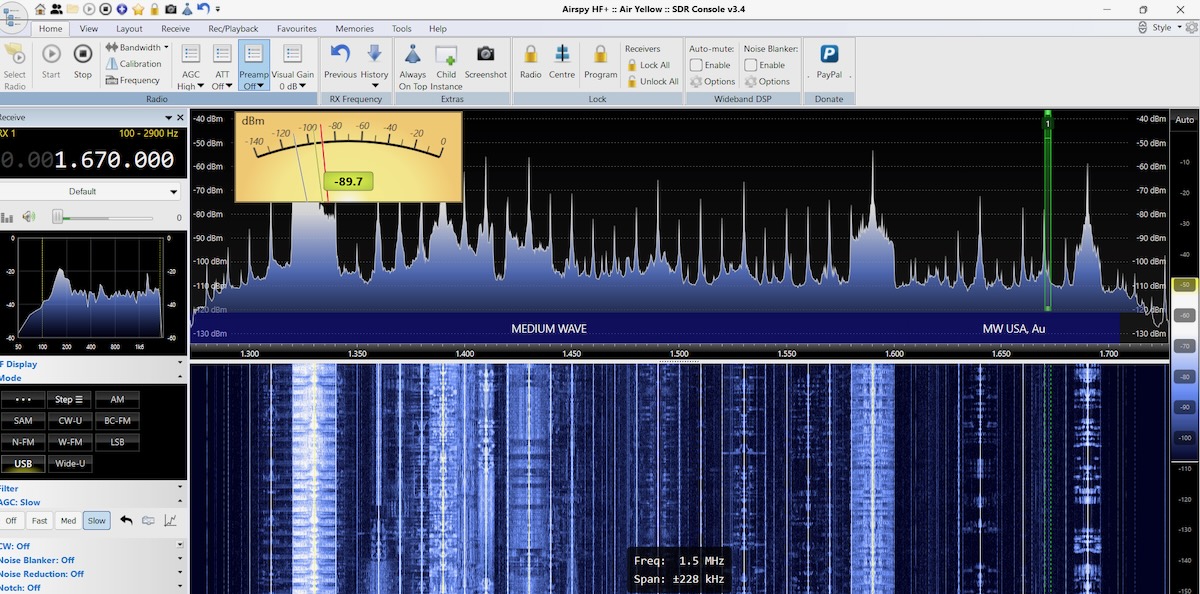
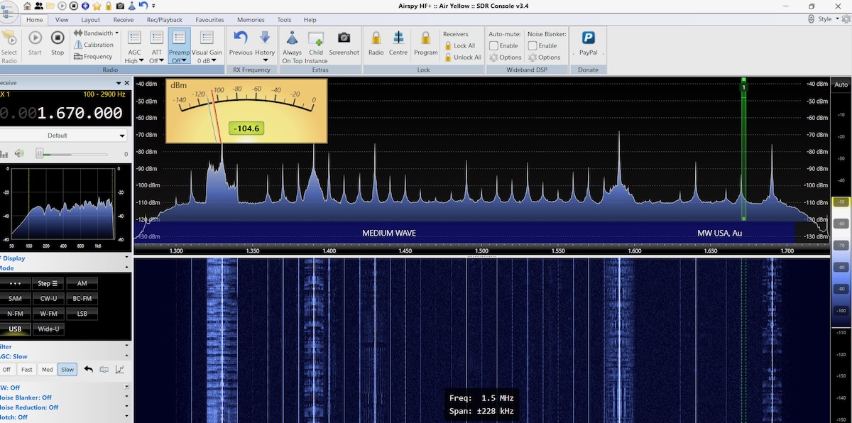
The MLA-30+, on the other hand, isn’t good for much beyond hearing the strongest local signals on medium wave.
When I ran these tests in the late morning, WWV on 5 MHz was the only signal in the 60-meter band. It had a very listenable signal on the PA0RDT.
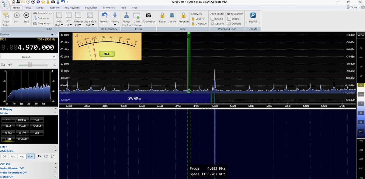
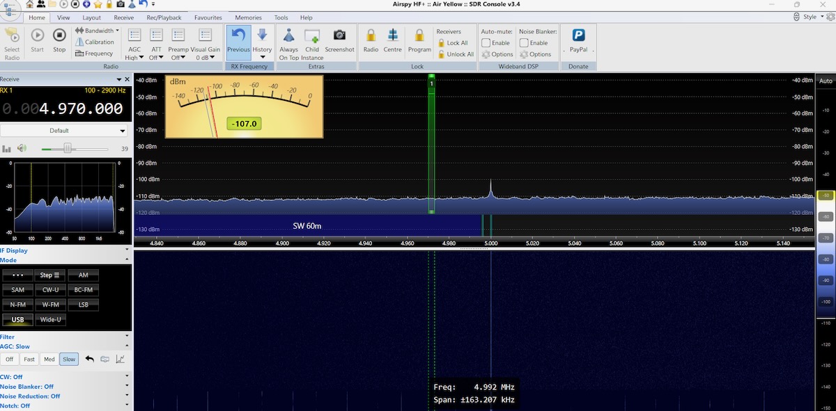
But on the MLA-30+, WWV was barely there.
Likewise on 49 meters, CFRX on 6070 kHz was very clear on the PA0RDT but barely listenable on the MLA-30+. But when I moved up to 31 meters, the difference between the antennas mostly disappeared, as in these images made in Kansas. The PA0RDT is top and the MLA-30+ on the bottom.
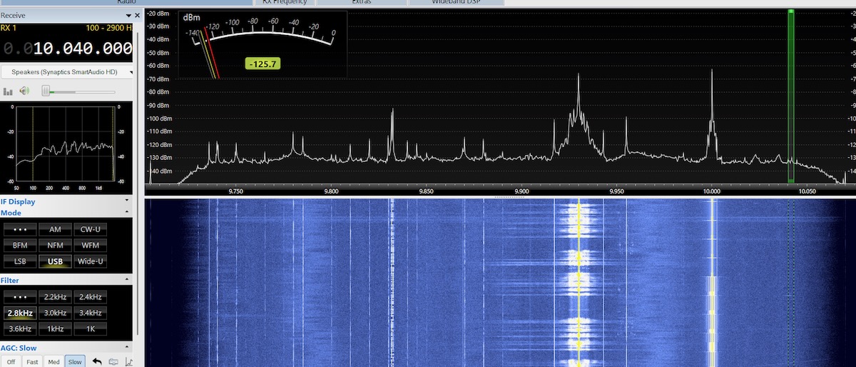
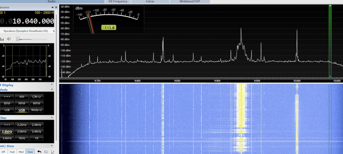
On 25 meters, the PA0RDT is picking up a lot of noise and the signals are not that strong. Nor were signals very strong on 19, 16, 0r 13 meters.
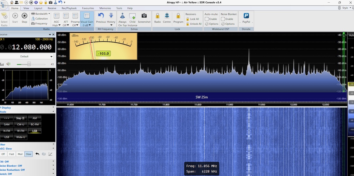
However, on 25 meters with the MLA-30+ there isn’t much noise and the signals are booming in. And 19, 16, and 13 meters likewise had strong signals.

So the PA0RDT is clearly the best antenna for MW and the lower shortwave bands, but it doesn’t do as well on the higher bands. This wasn’t a surprise to me as I’ve always felt that the PA0RDT underperformed above nine or ten Megahertz. The MLA-30+ was abysmal at the lower frequencies but worked better or just as well in the middle and higher shortwave bands. The best antenna is another antenna. Each one performs better in different situations. But I couldn’t help but wonder … was the problem with the MLA-30+ that small steel wire loop?

Look for Don’s Part 2 article next weekend on the SWLing Post!

Giuseppe’s Clever Homebrew Ferrite Antenna for MW and SW Listening

Screenshot

Many thanks to SWLing Post contributor, Giuseppe Morlè, who writes:

Dear Thomas,
I’m Giuseppe Morlè, IZ0GZW, from Formia in central Italy on the Tyrrhenian Sea.

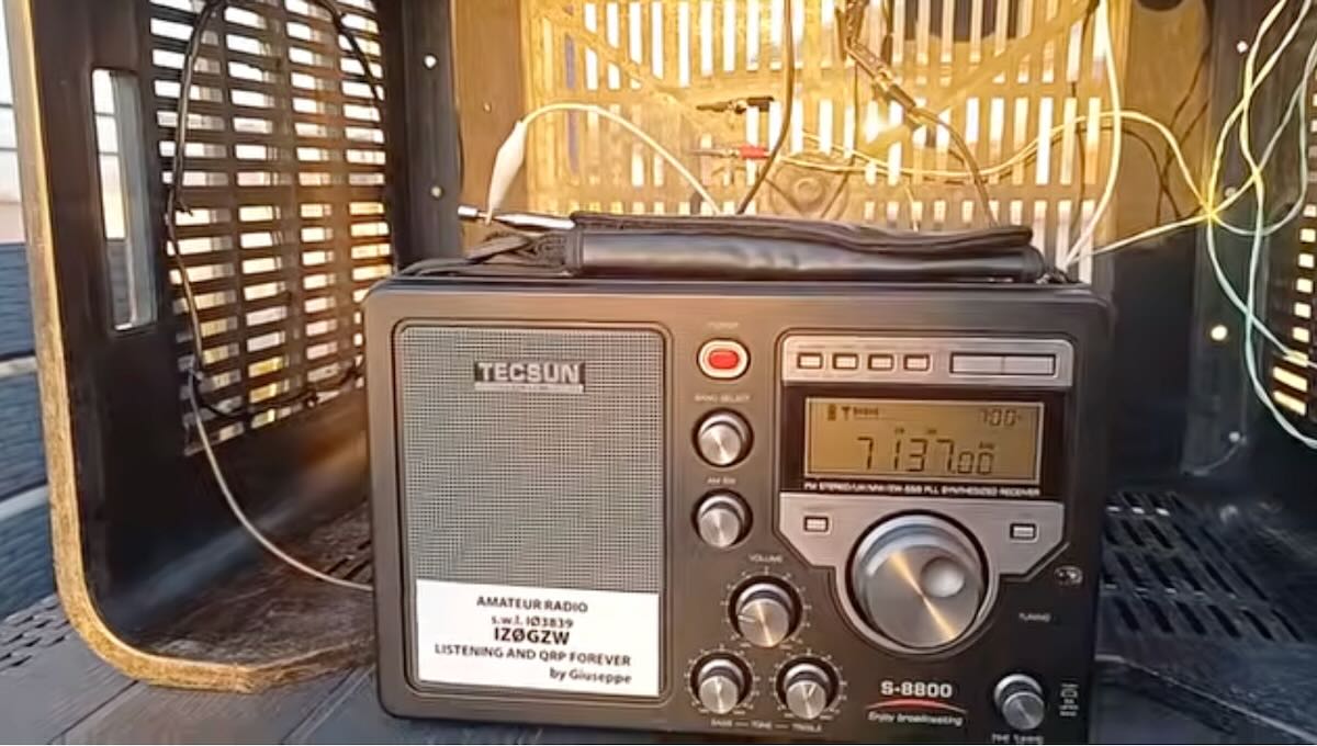
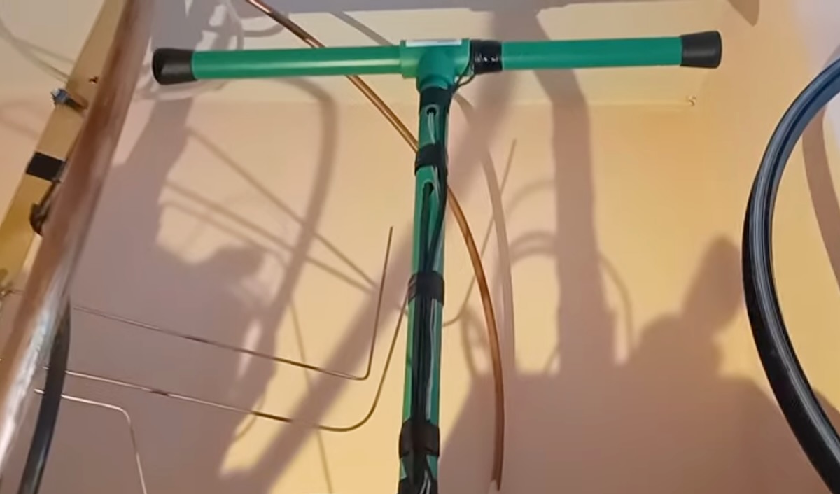
This is one of my builds from a few years ago: the T Ferrite antenna. It’s a minimal antenna designed mainly for mediumwave, but it also performs well on shortwave.

Inside the tube at the top are two 12 cm ferrite rods with 32 turns of telephone wire wrapped around them—this section is for mediumwave. Then, on the outside of the tube, I added four more turns for shortwave. A variable capacitor of about 1000 pF completes the circuit.

Shortwave is activated with an alligator clip. When the clip is removed, only the mediumwave section is active.

I tested this antenna with my old Trio 9R-59DS from the 1970s—a tube receiver still in perfect condition. To my pleasant surprise, the receiver paired beautifully with the antenna.

These tests were done on mediumwave in the early afternoon yesterday while it was still light outside. With the antenna placed above the receiver inside my shack, I was able to receive stations from across the Mediterranean basin and Eastern Europe, even in areas where the sun had already set. I really enjoy testing this antenna before evening, and I’m very satisfied with its performance.

You can see the results in this video on my YouTube channel:

I hope this will be of interest to the friends in the SWLing Post community.

Best regards to you and to all,
Giuseppe Morlè, IZ0GZW

We always enjoy checking out your homebrew antenna designs, Giuseppe! Thank you!

A HUGE difference . . .

By Jock Elliott, KB2GOM

It was a remark from Sebastian Schlüter in response to this post – https://swling.com/blog/2025/10/some-really-inexpensive-ways-to-perhaps-improve-your-shortwave-listening — that sparked today’s post.

He said:

If your RFI is really high, your best weapon is a magnetic loop antenna aka small receive loop. At home, my RFI is so high that I don’t benefit from a larger/longer antenna. For example: Using the telescopic antenna (75 cm) vs using 3m of wire. Reason is that the signal-to-noise ratio is roughly the same in both cases and that all of those very weak signals are below the noise floor anyway, and the ones that make it through the noise are already strong enough to be received with the telescopic only. Conclusion: In a high RFI environment, it’s not about maximising the signal strength but maximising the SNR. You need to find an antenna type that will pick up less of that RFI. A cheap and simple antenna for this is the small receive loop. For a start, you can use a cheap wire terminal with 3.5mm mono jack. Using a 1:1 balun further improves the result.

What really struck my eye was this:

A cheap and simple antenna for this is the small receive loop. For a start, you can use a cheap wire terminal with 3.5mm mono jack.

My CCrane Skywave SSB 2 came with a wire terminal with a 3.5 mono jack, I realized. I hooked it up to my 45-foot horizontal room loop (a single strand of insulated wire run around the top of window frames and bookcases in my radio shack), and then ran the following experiment.

Using the scan function on the Skywave SSB 2, I scanned the shortwave bands using the whip antenna, and then I did it with the loop plugged into the external antenna socket.

The results:

CCrane Skywave SSB 2

Whip antenna: 4 stations detected.                             Loop antenna: 13 stations detected.

Then I tried the same experiment with a Tecsun PL-880.

The results:

Tecsun PL-880

Whip antenna: 8 stations detected                              Loop antenna: 15 stations detected.

Clearly, Sebastian’s suggestion of plugging in a simple wire loop makes a huge difference. And, I should note, I didn’t play fair. I did the test while 3 scanners, an LED light, and two UHF/VHF ham transceivers were operating in the vicinity and probably generating RFI.

So now the question: I ran the experiment with a 45-foot simple loop. What do you suppose would be the minimum wire length for an effective simple wire loop? I look forward to your input.

Coupling Three Homebew Antennas for 40-Meter DX

Many thanks to SWLing Post contributor Giuseppe Morlè, who writes:

Dear Thomas and Friends,

I’m Giuseppe Morlè (IZ0GZW) from Formia, in central Italy on the Tyrrhenian Sea.

This time I wanted to experiment by combining three different antennas that interact with one another through induction. In the video, you’ll see the Milk Box Loop, the SW/MW Tablet, and the Wire Coil all working together to capture very faint 40-meter signals from W2V in North Carolina and ZL3CHE in New Zealand.

This experiment is especially promising as we move into the fall season, when nighttime listening on 40 meters becomes even more interesting.

I’ll continue testing with this fun, simple, and free antenna. You can see more in this video:

Thank you all, and happy listening!

—Giuseppe (IZ0GZW)

Thank you so much for sharing another one of your antenna experiments and impressive results, Giuseppe! 

Giuseppe’s Ingenious Recycled Antenna Board for SW & MW Listening

Screenshot

Many thanks to SWLing Post contributor Giuseppe Morlè, who writes:

Dear Thomas,

I’m Giuseppe Morlè, IZ0GZW, from Formia, in central Italy on the Tyrrhenian Sea.

I’d like to show you my antenna board for shortwave and mediumwave listening with portable receivers like the Tecsun PL-660.

The board has two distinct circuits:

      • A small-diameter loop with two turns for shortwave reception (3.5–18 MHz).
      • Three ferrite rods with 30 turns each, plus a four-turn link coil that carries the signal to the receiver for mediumwave reception.

In the video, you’ll see how the board works on its own, and then how performance improves when I connect a 15-meter wire and throw it over the balcony of my house. In that case, the signal becomes much stronger.

Tuning is done with a 900 pF variable capacitor. To listen to mediumwave, I simply disconnect one side of the shortwave loop. With just that single variable capacitor, I can tune all of the bands.

It’s a surprisingly effective antenna for small portable receivers, and it’s built entirely from recycled materials—at no cost.

I hope you enjoy it. Greetings to all the friends of the SWLing Post.

73, Giuseppe Morlè, IZ0GZW

Click here to view on YouTube.

Many thanks, Giuseppe, for once again sharing your creativity with us. I’m always impressed by the antennas you design and by the performance you achieve—especially considering they’re largely homebrewed from recycled parts. That’s radio at its very best!

[Note that his video is in Italian, but you can turn on subtitles for your preferred language.]