Many thanks to SWLing Post contributor Don Moore–noted author, traveler, and DXer–who shares the following post:
Two Portable Antennas for Remote DXing (Part Two)
By Don Moore
Don’s traveling DX stories can be found in his book Tales of a Vagabond DXer [SWLing Post affiliate link]. If you’ve already read his book and enjoyed it, do Don a favor and leave a review on Amazon.
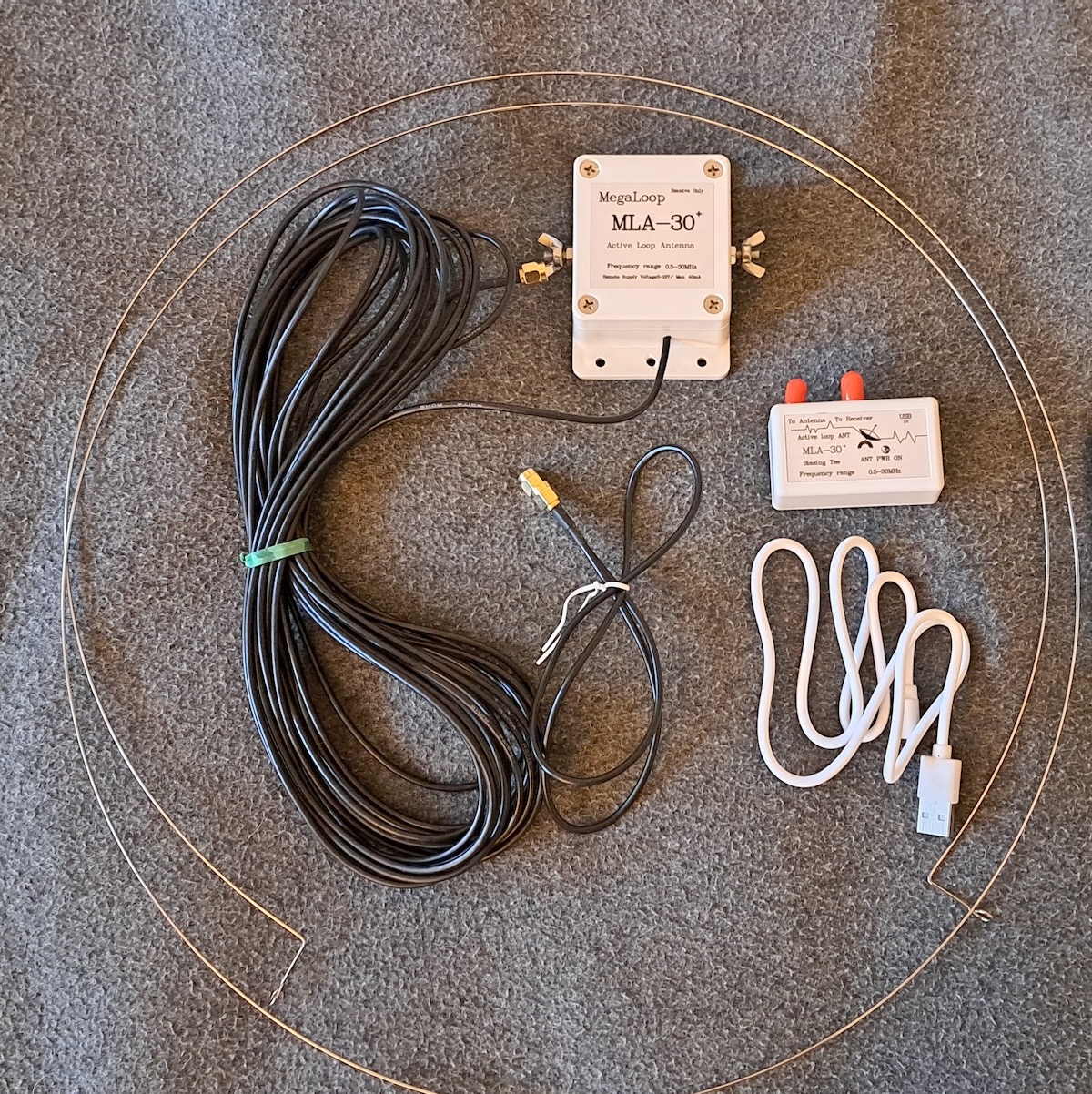
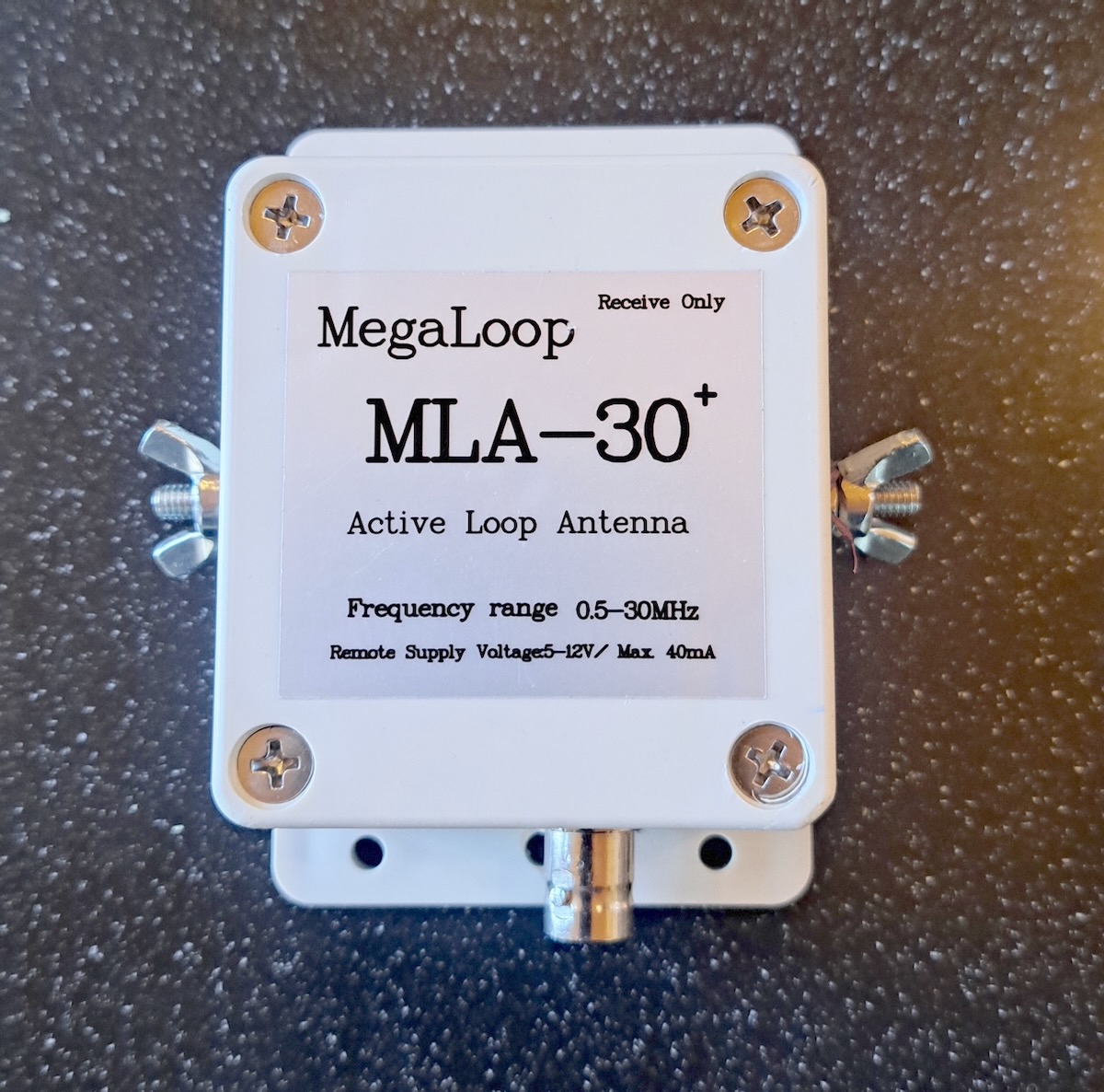
In my initial comparison of the PA0RDT mini-whip and the MLA-30+ MegaLoop, the mini-whip performed best on medium wave and the lower shortwave bands, while the loop worked better on the higher bands. But, I wondered, why should the MLA-30+ be restricted to that small steel loop? The wire loops I use with my Wellbrook ALA-100LN typically range from twenty to fifty meters in circumference.
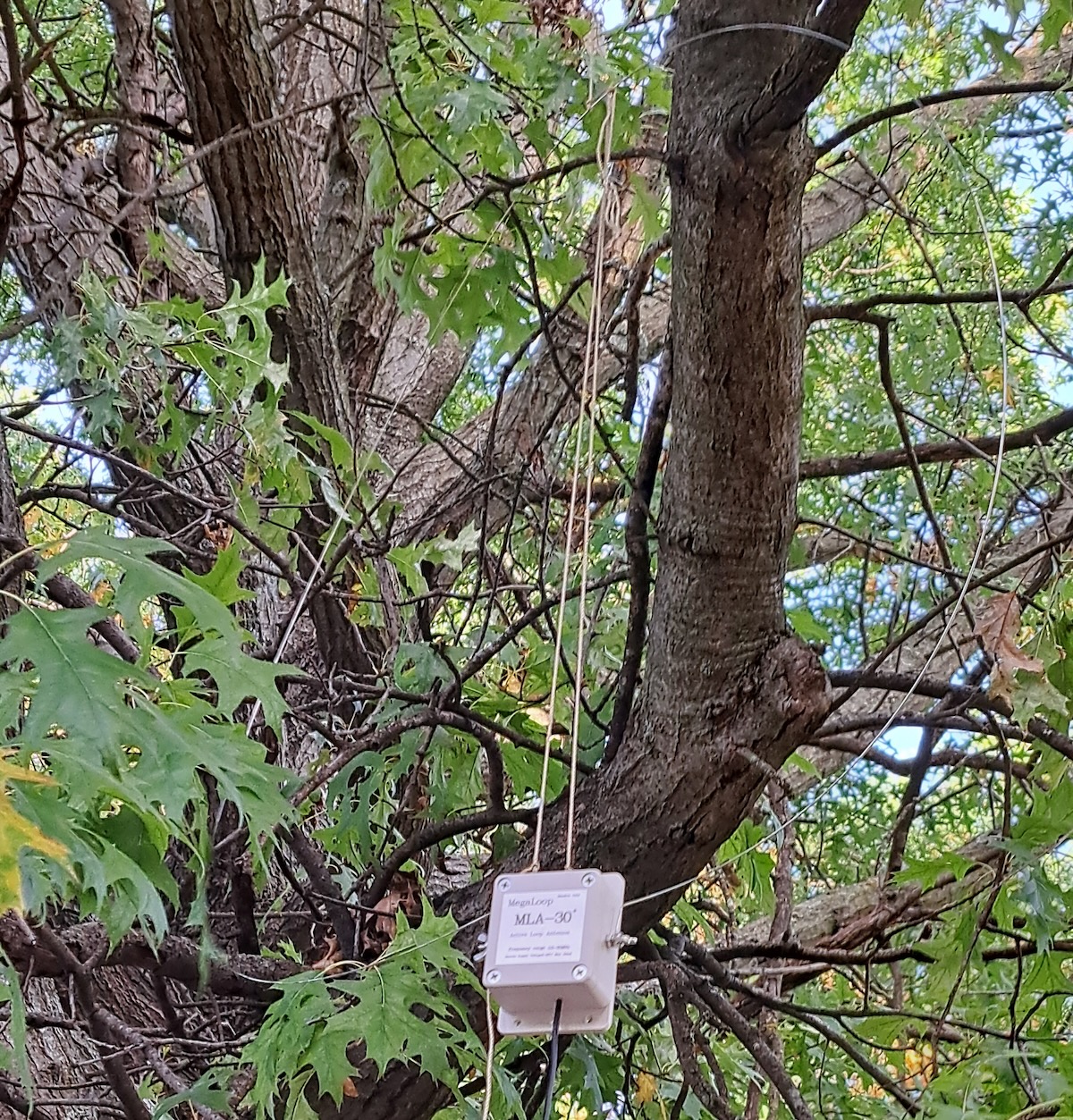
I threw a twenty-five-meter wire over a tree branch and formed it into a delta with the MLA-30+ in the bottom center. Remember, I was testing in the northern Chicago suburbs. My SDRs were completely overloaded. Medium wave was useless and I had strong MW stations all over the shortwave bands. The MLA-30+ doesn’t have the same strong-signal handling capabilities as the Wellbrook. And there are a lot of strong medium wave signals in the Chicago suburbs.
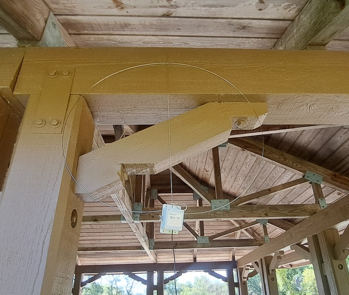
So I took that wire down and replaced it with a loop of twelve meters circumference.

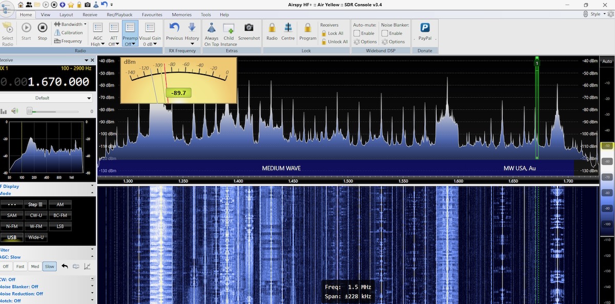
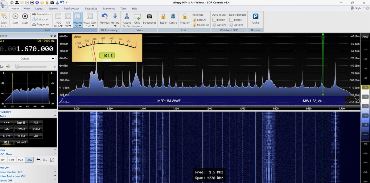
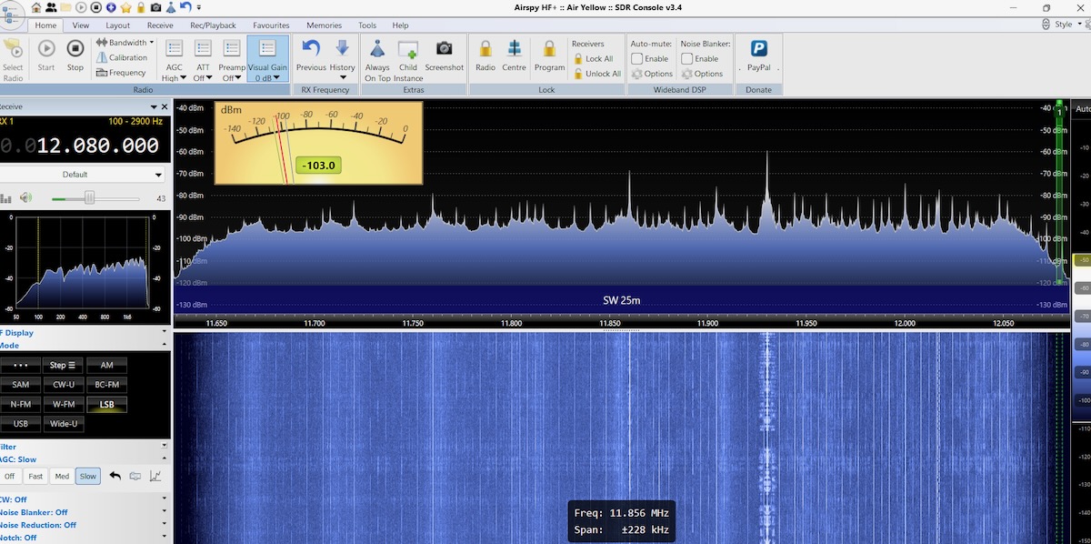
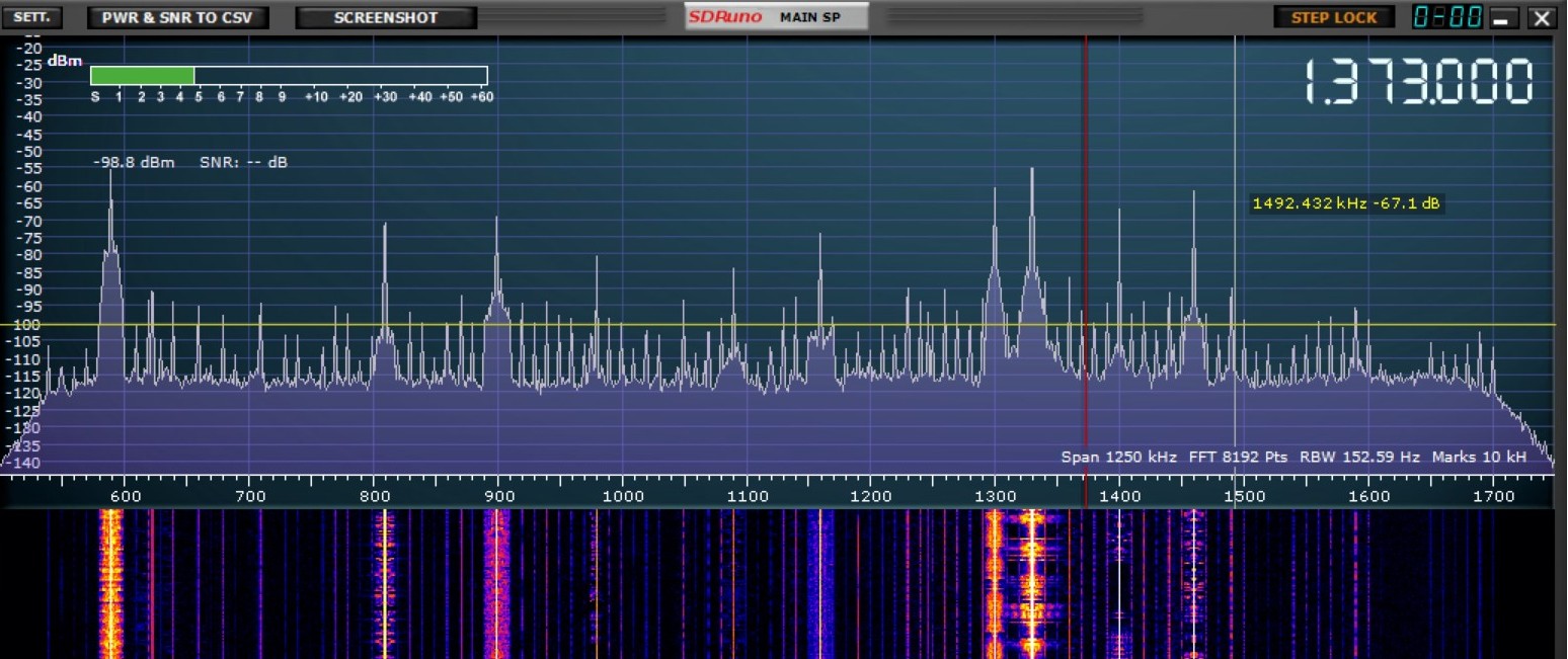
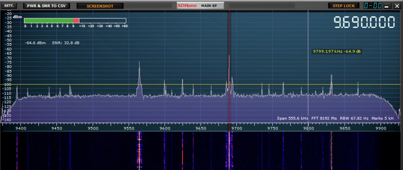
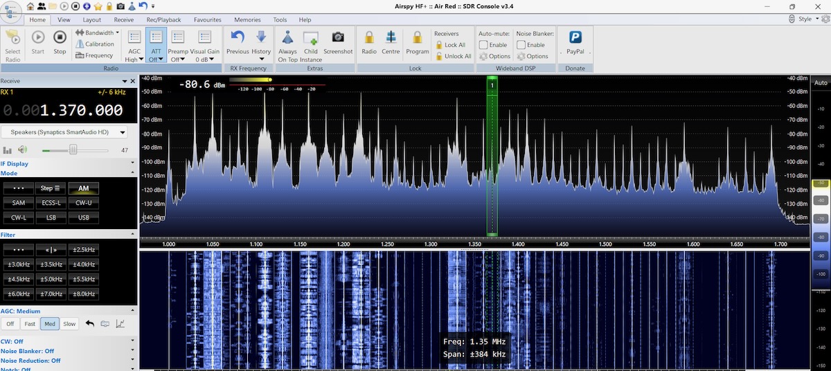
That did the trick. I had lots of signals on medium wave without the overloading. Here’s what the upper end of the MW band now looked like with the MLA-30+.
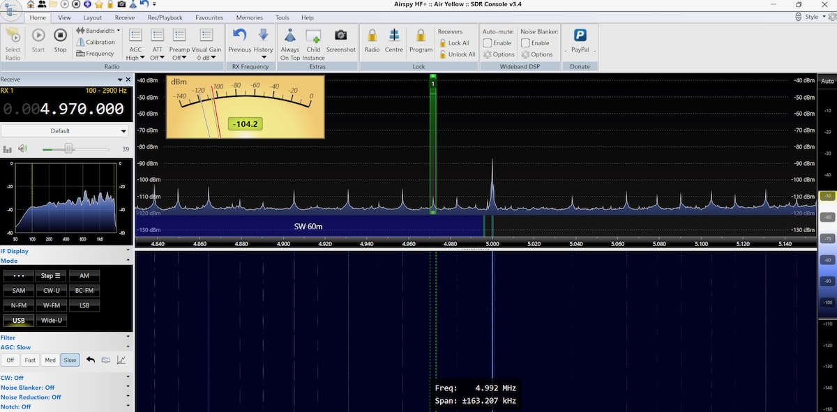
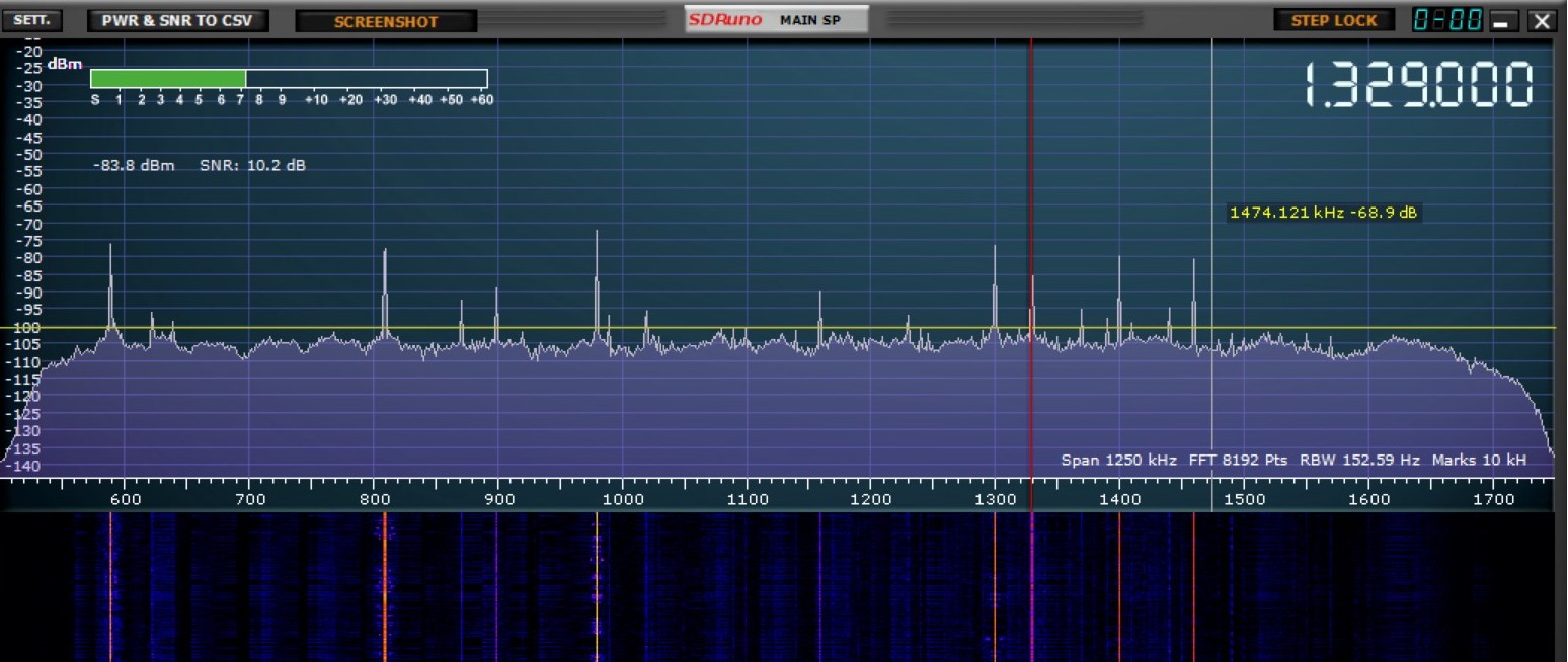
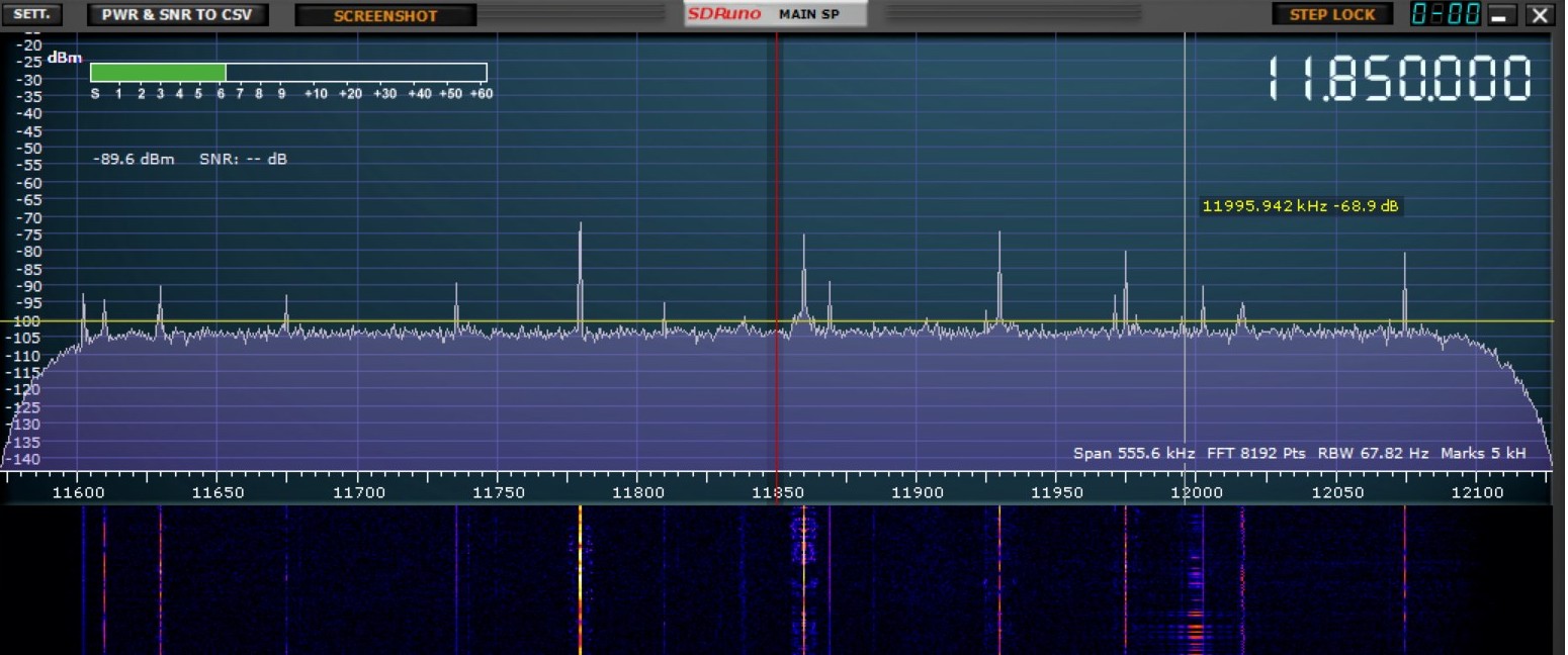
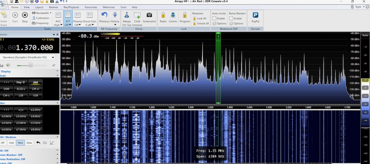
For comparison, here’s the same wire loop using the Wellbrook ALA-100LN. The Wellbrook has a slightly lower noise floor but otherwise the signals are about the same.
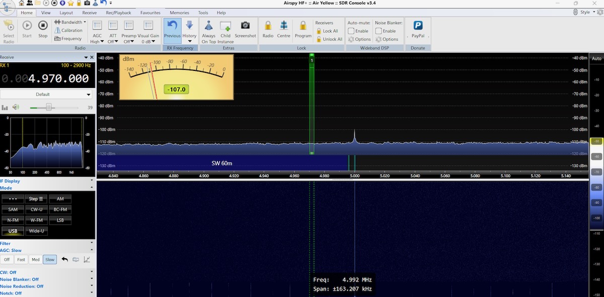
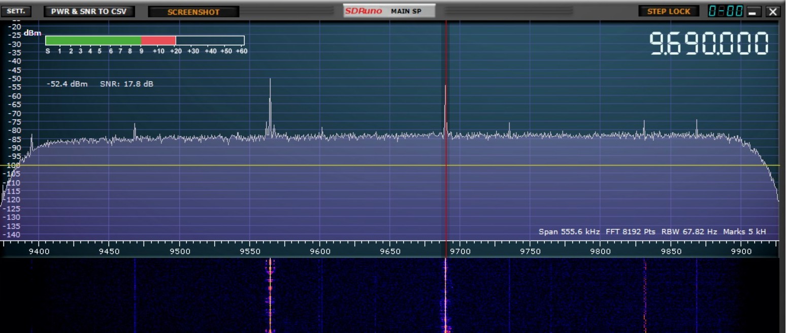
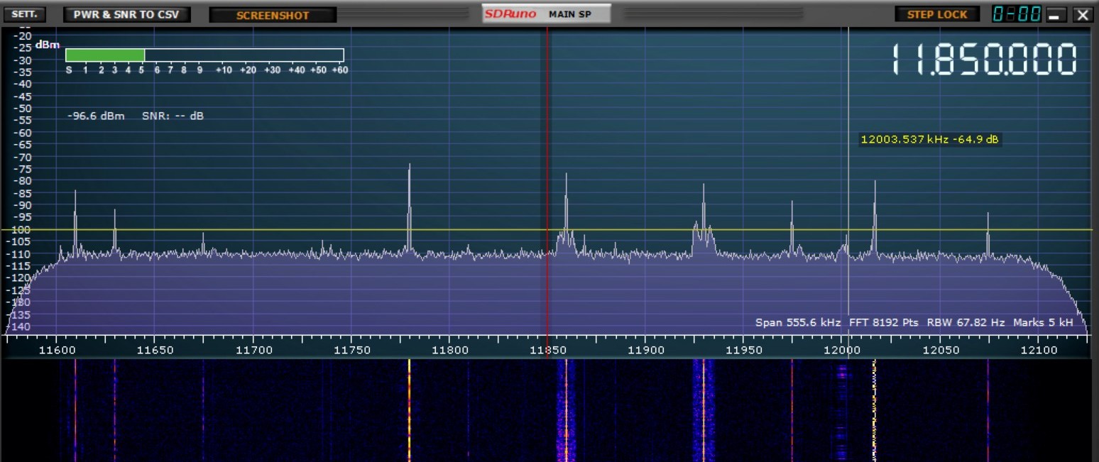
Out of curiosity, I replaced the Wellbrook power unit with the Bias-T from the MLA-30+ but left the Wellbrook antenna head unit in place. With this hybrid setup there’s no visible difference with the full Wellbrook.
I was satisfied with my findings but I still wondered how much wire the MLA-30+ could handle. A few weeks later I ran some more tests in Kansas, where I knew the dial wouldn’t be as crowded. The MLA-30+ easily handled a 25-meter delta loop without overloading.
Two weeks after doing the Kansas tests I was at a DXpedition in rural western Pennsylvania. The MLA-30+ worked fine with a 40-meter circumference loop, other than being a tad noisier than the Wellbrook with the same wire. So how much wire you can use with the MLA-30+ components depends on how strong your local medium wave stations are.
Findings
From the SDR images above it would be easy to conclude that with the right length of wire an MLA-30+ is just as good as a Wellbrook ALA-100LN even though it is significantly cheaper. But that’s not the full picture. Back in the 1990s my Drake R-8 cost about three times what my Sony ICF-2010 did. All other things being equal, I would say that 95% of the DX heard on the Drake could have been heard equally well on the Sony. I wanted the Drake for the other five percent.
I have no doubt that if I did a very careful head-to-head comparison of the two units under serious DX conditions on the same wire that the Wellbrook would get things the MLA-30+ couldn’t. But I suspect the difference would be around that five percent mark. I’m willing to accept that tradeoff for an effective cheap light-weight travel antenna. And the MLA-30+ is like having two antennas in one. I can use it with the steel loop in limited space situations or with a larger wire loop when I have access to some garden space with a tree. Together, the MLA-30+ and the PA0RDT make the perfect DX travel antennas.
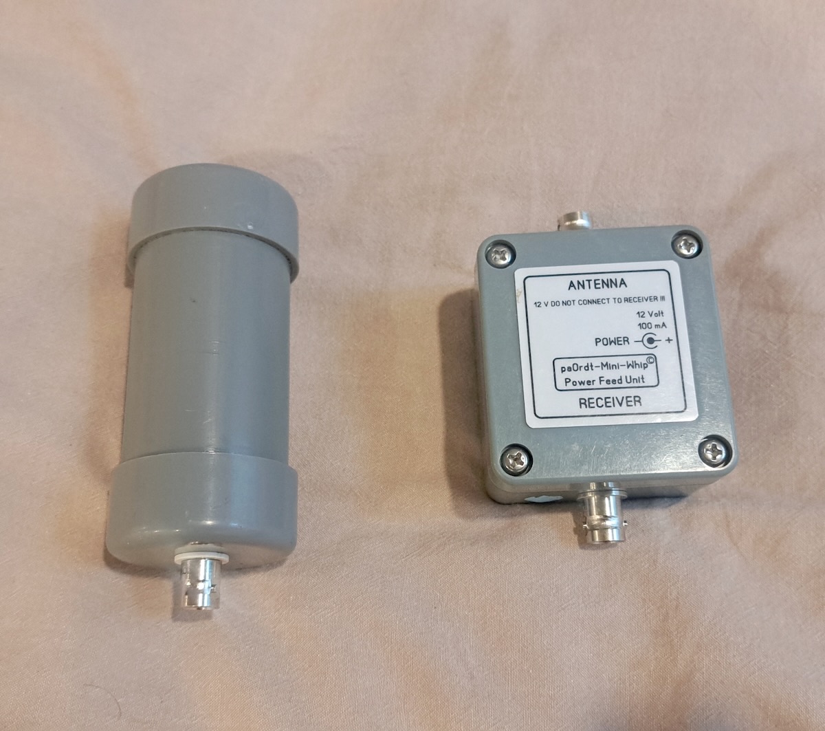
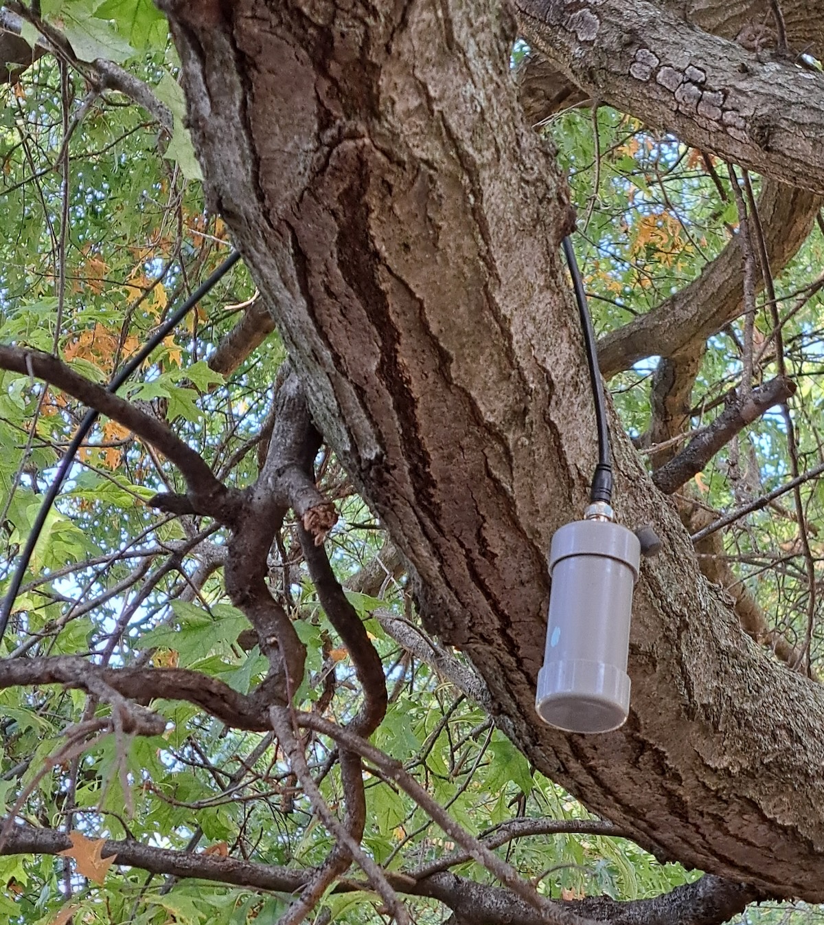
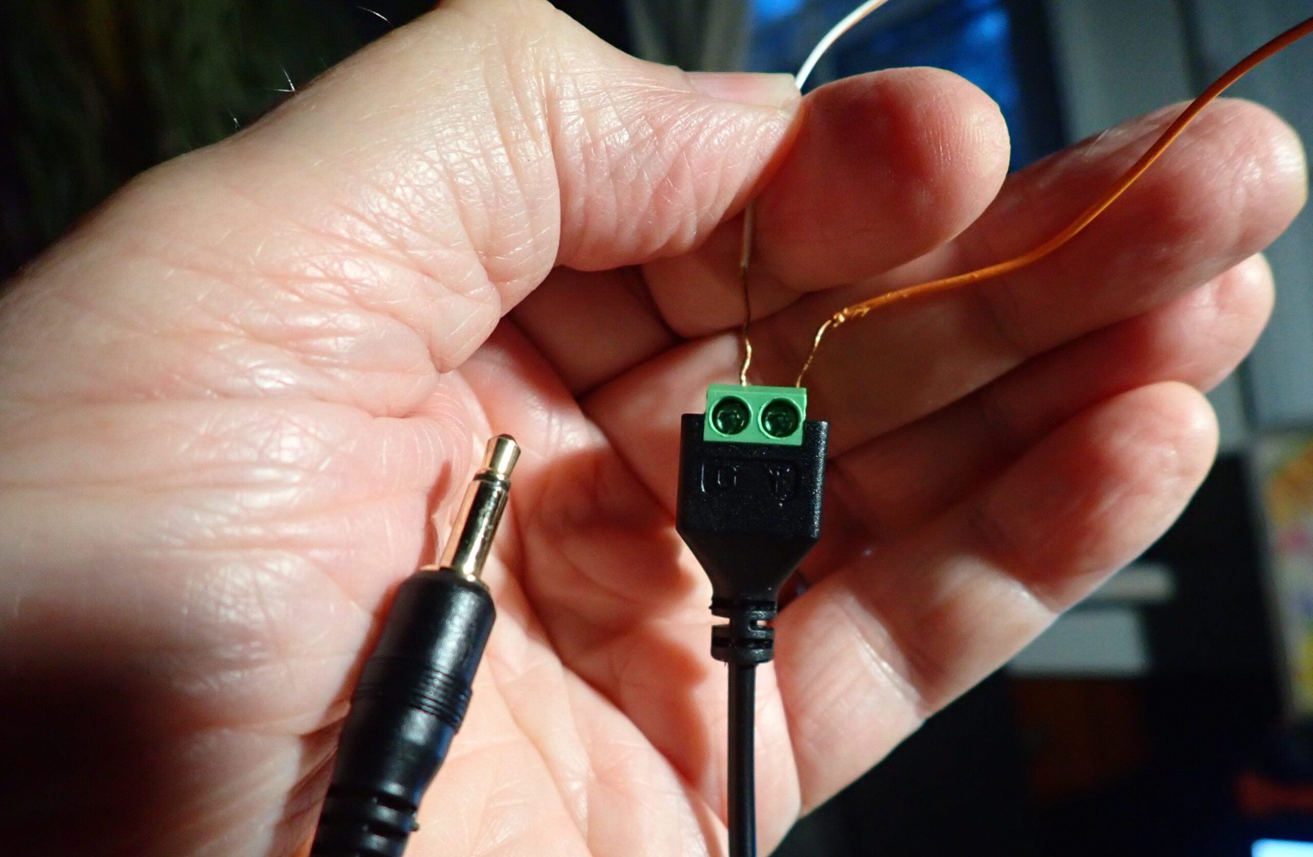
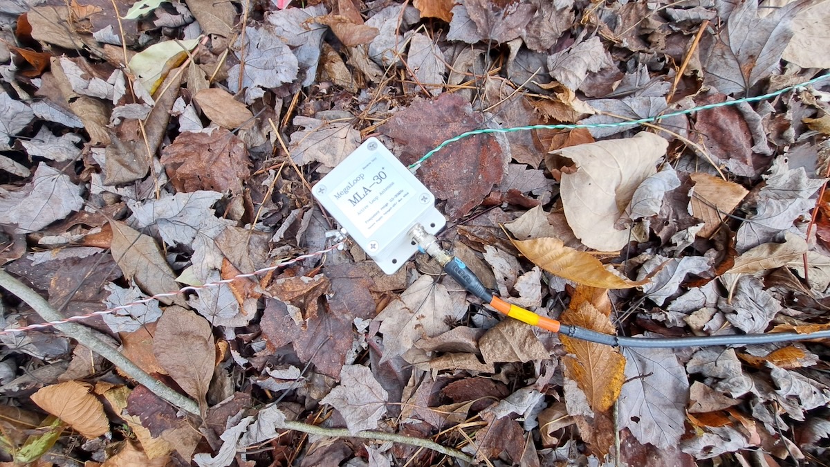
The only thing I didn’t like about the MLA-30+ was that pre-attached coax cable. It’s not the best quality and I’d rather carry my own cable. I’m not very handy with a soldering iron in tight spaces but at our recent DXpedition my friend Bill Nollman replaced the coax with a BNC jack for me.
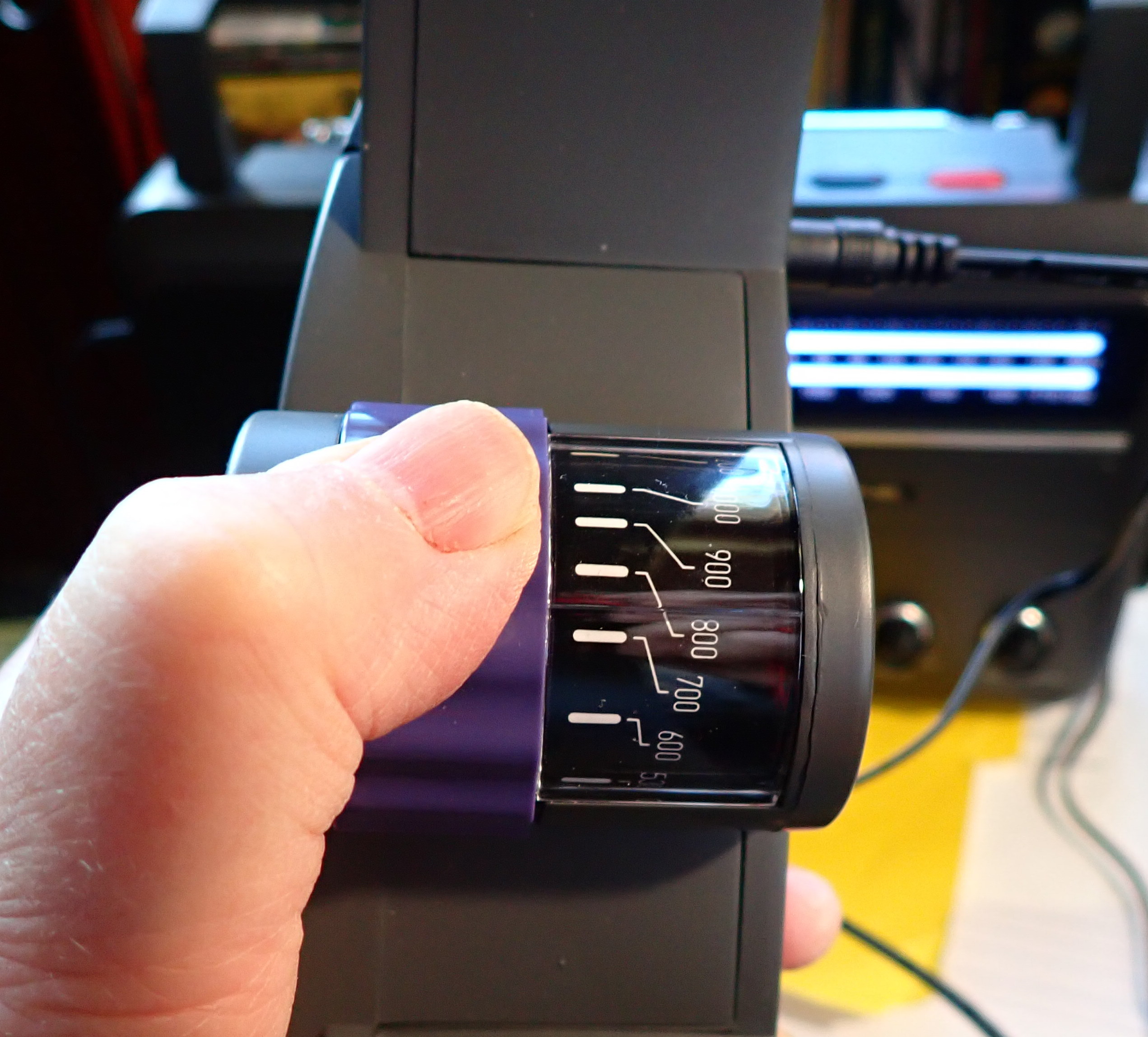
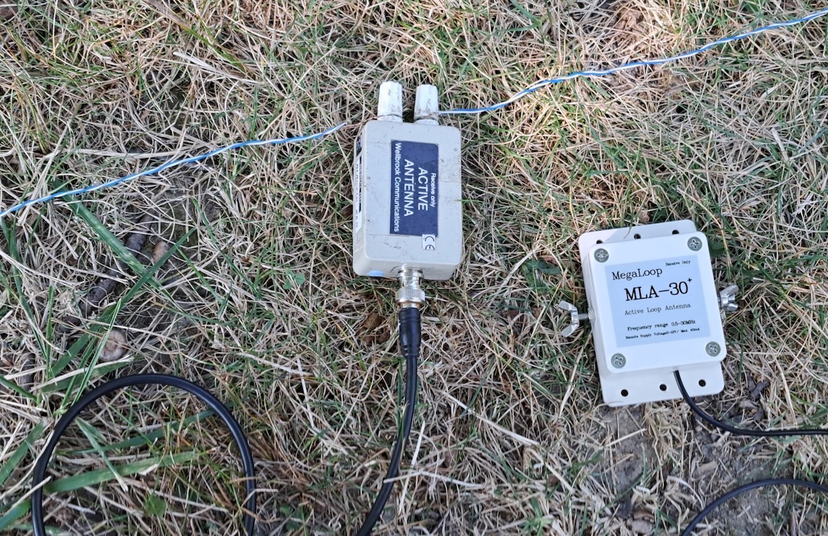
The MLA-30+ now looks like this when connected to a wire loop.
Finally, I should address powering the MLA-30+ via USB. While it can be connected to a spare USB port on your laptop, I found doing that sometimes introduced a tad more noise. Instead I’ve been using one of those battery packs used for recharging cellphones. Mine is rated at 6700 mAh and it can power the MLA-30+ for over 48 hours before needing a recharge. But be sure to test yours before doing any serious DXing. I’ve read that some power packs have a minimum required power draw and will automatically shut off if the draw is too low.
Another Option?
While I was finishing this article I heard about another option from my friend Guy Atkins. This antenna is a combination of the YouLoop with a low-priced Chinese made clone of the LZ1AQ amplifier. Some users say it’s better than the MLA-30+. Guy says it works well on shortwave up to 16 meters but he hasn’t tried it on medium wave. Guy says it’s a “low price, good value” antenna. I’m traveling in Southeast Asia for the winter but will definitely have to try this antenna when I get back to the USA. So maybe there will be a follow-up article next summer.
Links
[Note: Amazon links are affiliate and support the SWLing Post at no cost to you.]
Info on ordering a quality PA0RDT from Roelof Bakker. (Other cheaper versions have had issues with quality control.)
https://dl1dbc.net/SAQ/miniwhip.html
There are various versions of the MLA-30+ and the original MLA-30. This is the version that Mark Taylor recommended and that I bought.
There are numerous YouTube videos on using and modifying both versions of the MLA-30+. This one shows how to replace the coax with a BNC jack.
https://www.youtube.com/watch?v=OAqh2Lawwdc
Here’s the Amazon link for the YouLoop/LZ1AQ antenna that Guy has.
And the same antenna on Ali Express.