
Category Archives: Tutorials

MLite-880: A lot of remarks that may also help you enjoying it more 

By 13dka

After all the recent buzz and watching and reading every video, review, and discussion thread/group I could find about this radio, as per usual, I knew I had to buy one in order to find out if I want one…again. This is not a review, but taking notes while getting acquainted with it and gathering the technical information I couldn’t find, I started thinking that sharing this might be at least entertaining for other MLite owners, maybe helpful to elaborate on a few things for newcomers to complex radios and SDRs on the way and also to tell the undecided why I started calling it names so I had to keep it. Sounds terrible and very much like a review, so let’s get on with it.

Chapter One: What is this thing anyway?  

I couldn’t help noticing the higher-than-usual pile-up of “game changer”, “new era,” or “the radio <brand name> never made” expressions coming with this one, and I was confused. Sure, it is another small, self-contained SDR, functionally more or less just a mildly simplified Malahit redesign with a much simpler display in a more familiar shape, but the Malahits have been around for years, and they’re neither the first nor the only radios with this job description. I couldn’t quite understand what fueled the sudden interest, just because it doesn’t look like Spock’s preschool tricorder and more like the offspring of an Asian travel radio and a Scandinavian business phone? Really? Then I found the price tag and the light came on.

That it’s now also much easier to purchase the new Gründig Sputnik 880 as an official product with authorized firmware from Malahiteam’s new Chinese manufacturer obviously did it for me too, and it may speak even more to people who have really been waiting for an affordable, actual step-up from their first 473x-chip radio for so long that they bought 5 more of those in the meantime. I promise it may be quite an upgrade from any radio that looks similar, and I even deem it pretty user-friendly. However, it’s technically and conceptually still a Malahit and as such much closer to any other SDR hard- and software made to cater to the exotic desires some outspoken radio enthusiasts have, than to anything it is made to look like.

Unfortunately, this is really clashing with very frugal documentation and unusual technical secretiveness about what’s in there; people have to figure out many things on their own and fail at it, and I feel the mimicry is also fueling unrealistic expectations.

Chapter Two: Technical Notes

The “technical secretiveness” extends to filing the markings off most chips, so little is known about the innards of this receiver.  Russian YouTuber Alexey Igonin suspects a single-conversion SDR on shortwave (up to 27 MHz) becoming a dual-conversion radio above. The FM broadcast range appears to be a separate tuner active between 65 and 107.999 MHz and another VHF tuner from 108-165 MHz; both tuners are then downconverted to the high IF of the SW receiver. This abstract string of words explains to the initiated why oddities may be seen here and there, for example, when you tune to 108.00MHz

Operating concept

For a general description of the radio, menus, and general operation of the MLite, please refer to Dan Robinson’s and all the other excellent reviews. I want to sell you on the general concept centered around the telephone keypad, making it strangely not such a big deal for me that it has only one encoder knob and 16 buttons. It’s quite different from all button portables I have met:

Each function menu has its own button, assigned to 9 of the 12 buttons on the phone keypad.  Each function in these menus has a number, too.  That means you can memorize access to your frequently used functions by a 2-digit number, one for the menu, the other for the item you want, and in many cases, that’s all. Dial 25 for AM, 26 for SAM, 21 for USB without further action, 61 is the number of the IF filter warehouse expecting your orders via the knob (unless it isn’t), you get the idea. That means most functions on this radio have 2 buttons you need to tap, but they all have their own 2 buttons right on the front panel.

Direct frequency input is activated by button [4] and is accepting a couple of ways to enter a frequency followed by button [A] for kHz and [B] if you want MHz, e.g. “123*125 [B]” or “123125 [A]” take you to the same frequency, or just hit “123 [B]” to go to 123 MHz and tune up a little. Some even recent radios are much less tolerant and made me give up on typing in frequencies; this is not one of those.

Such an anachronistic flashback to early digitally controlled commercial radios/machines/things or DOS computers seems to be almost ironic on the face of this bundle of latest digital wonders.  But I think it could easily run circles around nested menus on a tiny touchscreen if you can adapt to it. The keys are not backlit but if you could dial 911 in the dark on an old landline telephone like the victim in an old crime show episode, you can position your fingers on the keypad to type “4-27555-A-21” (hyphens for clarity, it’s actually 42755A21), if you have firmware 1.5 or higher this will take you to the CB “highbander” calling channel in USB, hopefully entertaining you until the ambulance arrives.

Unfortunately, there are also multi-page menus like the [AUDIO] page with your filters, so “61” doesn’t always work, and e.g., the steps menu changes its buttons according to the mode, so the “mental phonebook” method becomes a little more involved. Still, when you exit and return to a menu it will still have that previously selected function assigned to the encoder to speed up things and it memorizes that for each menu individually, long press of the SQL [B] or NR [C] button (while they’re on!) takes you directly to their intensity setting in the menu…in short, things have been laid out very well and after a few days that became part of the fun this radio is. Summary: It’s a real asset because it allows you to fly this radio blind, for example, when you’re legally blind or just legally supposed to have your eyes on the road.  

Antenna Input, Impedance Switch, and Bias-T:

An understandable common misconception seems to be that the antenna switch [3][1] is toggling between the whip and the 1/8″ phone-type antenna jack. What actually happens when you insert a phone plug is that the whip is getting disconnected, and the switch is toggling between high and low input impedance. It seems rather important to understand that this high impedance input is provided by the additional amplifier needed for the whip; it remains in the signal path when you use the antenna jack.

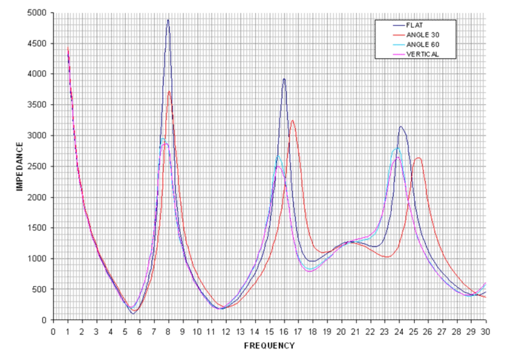
In general, switching impedance allows for external antenna configurations that would otherwise not work well, and in the presence of high local noise levels, the shielded input is highly preferable over open wires alligator-clipped to the whip in lieu of a missing Hi-Z input. Besides matching different antenna types, switching impedance can also increase the number of “good” frequency bands on the same (passive) antenna. Most antennas, including simple passive wire antennas like endfeds etc. exhibit a wild up and down of impedances over the wide range of wavelengths we SWLs use them on. When the impedance mismatch happens to be at its most loss-inducing extremes in the band of our choice, switching the input impedance may or may not improve reception:

VK6YSF’s impedance vs. frequency plot for an endfed antenna in different orientations

For example, a simple magmount whip on the car roof is often all you’d need for a bit of quality mobile SWLing, but impedance mismatches between the external whip, the cable, and the input can suck the life out of it on many frequencies. My “Little Wil” CB magmount doesn’t work well on 20m…switching to Hi-Z can fix this. In other bands, this will not improve anything, and the MLite is kind of giving a clue on this bad constellation by becoming very noisy when you switch to Hi-Z in these cases.

The additional amplifier helps with these small, lossy antennas, but that advantage can turn into the opposite when it gets overloaded by “full-size” antennas, and the simple logic “Hi-Z antenna works best on Hi-Z input” doesn’t always work anymore. Leaving this for everyone to figure out on their own is provoking bad results and bad rep.

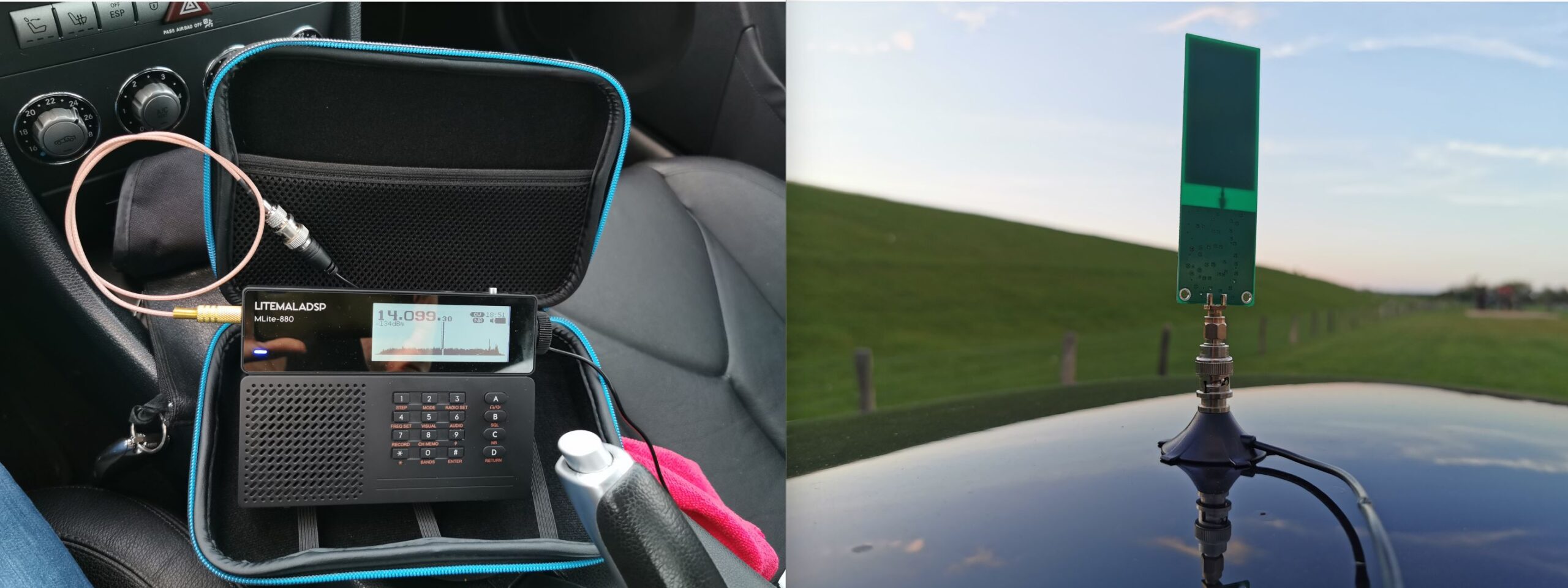
This radio offers to pass the (unregulated, drops during discharge!) battery voltage to the antenna jack for active antennas and LNAs at no extra fees. I could finally try if a tiny miniwhip could be a worthwhile low-profile solution for the car roof, one that gets enough shortwave in while keeping the considerable electromagnetic racket within the car out. Turns out the 15 bucks drawer-queen miniwhip PCB that was once powered up for 10 seconds 10 years ago seems to be pretty happy with sitting on a car roof, it works almost as well as a 47″/1.20m telescopic whip while theoretically giving a very low profile, avoiding the RC-car looks. Too bad nobody makes an autobahn speed compatible, magmount miniwhip for cars, hint, hint, nudge, nudge.

Spectrum Display

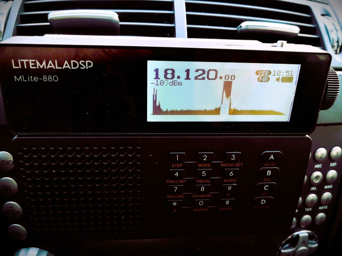
If the Panicsonic RF-KGB-65 is your first radio with a spectrum display, welcome or welcome back to the world of radios that have something nice to look at. I appreciate the feature too, and maybe it’s a good thing that it doesn’t overwhelm people with information, but a spectrum graph line without scale/grid to tell how wide, far apart and strong signals are on that spectrum does not provide very much information beyond revealing the pure existence of something left and right of your tuned frequency. Still a great thing to have and a mesmerizing and instructive eye catcher and only a white cat can make you look more like someone out of a James Bond movie while consuming almost no battery.

How much of the spectrum you can see depends: What you actually get anywhere on AM/SW/VHF is a 40 kHz portion of the band, and you can’t zoom in or out, likely because that’s how much you can reasonably expect to show on a low-resolution dot-matrix display, expecting narrowband signals on the band. Narrow signals are also why the spectrum line should be filled, or unmodulated carriers/CW will be represented by a single, hard-to-see dot instead of a full single line. In WFM we get roughly 600kHz of spectrum from that display, which is just the FM equivalent of “not an awful lot”. On the plus side, you almost never have to bother with spectrum settings (which can be a rabbit hole, trust me).

Averaging means that the height of each dot in the spectrum line is calculated off more samples, the more samples, the longer they live on the display, too. This allows the display (and us) to differentiate between weak signals and noise. I found the most useful averaging settings in the upper half of the range 50-99, not quite as good as a waterfall display (= a history of spectrum plots), but ’99’ will allow you to blink very slowly and not miss an activity, at the cost of display responsiveness. Too little averaging also makes you miss fast events on the “bandscope” even when they’re loud.

To alleviate you from more settings, the radio is automatically scaling the levels of the spectrum line. If a strong station comes up within the spectrum passband (not necessarily within the 40 kHz display range), the scaling changes and the visual noise floor drops. This looks confusingly the same as if the AGC was “pumping” and radio would be actually desensitized by that station. This can actually happen, but then you will also clearly hear the AGC “pumping” the noise floor as the display seems to indicate. That scaling also means that the visual noise floor does not reflect the actual level or proportion of the noise floor; deriving SNR differences from the graphical representation is not always possible.

Both spectrum and signal meter displays seem to indicate frontend input levels pre-AGC; changing the gain in the radio does not affect the display (the built-in attenuator does, of course). Besides the spectrum, the display has the usual status indicators but the very limited display space may not allow for all indicators people could wish for. The bargraph signal meter can be switched to an alphanumeric dBm display aligned with the classic S-meter 6 dB/step scale (not dB/?V) as indicated by the meter refusing to measure signals beyond -73dBm (S9), in which case it just notifies you of the surplus level by adding a ‘greater than’ sign to the value, “>-73dBm”. Still, the numerical measurement is pretty averaged/integrated and therefore nicely readable below that. Which is good because the meter does indicate the noise floor.

Controlling Gain, AGC, and ATT:

Most of the radios the MLite-880 is cosplaying have an AGC that doesn’t require any interaction and many of them just have a “one size fits nobody” response curve for AM and SSB. Likewise, most portables don’t have gain control beyond a “Local/DX” switch on the side. The MLite AGC, on the other hand, offers 4 release speeds with variable ‘Gain’ and ‘Limit’ parameters, plus a manual gain control option.

Of course, I’m pulling this out of the nose since it’s all not documented, based on my observations and similar arrangements: In very simple words, ‘Limit’ sets how loud you want the loudest stations to be, and ‘Gain’ is how loud you need to have the weakest station, particularly in SSB.

To elaborate on that, ‘Limit’ sets the threshold level where a signal causes gain reduction, and ‘Gain’ is basically the “RF gain” control some people think is missing on this radio, giving remarkable gain reserves (60dB). Use ‘Gain’ to bring weak stations closer to the ‘Limit’ threshold. “Limit” defaults to “75dB” and it looks like signals around S9 are going to be, well, limited to that, which means raising that is lowering the overall AGC action as much as decreasing gain while it increases the volume. The closer these two values get to each other, the more compressed, noisy, and “pumping” the channel will sound. Keep in mind that gain does not equal sensitivity, and avoiding AGC action is often preferable over the convenience of not needing to touch the volume knob. Matching gain to the conditions and signal you want to receive is also a prerequisite to make the most out of the noise reduction. This old clip demonstrates the difference it can make when you can control gain to avoid getting loud signals squeezed by AGC and the noise floor not being pulled up unnecessarily (same transmission received on a D-808 (no gain control) vs. a Belka (has gain control), recorded simultaneously):

A sound like this is the sign that you may want to reduce ‘Gain’, or use the attenuator (dial “33”) to that effect.

I’m not sure I understand or experience all of the issues some seem to have with the AGC; other than that, it does not default to the hottest gain settings it is capable of, which adds to a different problem with this radio – the harsh drop in volume in SSB/CW and WFM modes compared to AM/SAM/NFM. That also might be pushing people towards increasing gain beyond reasonable values to compensate.

The ATT can be set to 36dB of attenuation in 6 dB-steps, but for some reason, I can see at best 15dB of it on signals anywhere on the S-meter scale, high or low, which seems as strange as the fact that it didn’t help in the only overload situation I had with this radio. If this is your first ATTenuator, it’s supposed to decrease the signal in front of all amplifier stages, unlike most RF gain controls, it is often the radio’s only reliable (onboard) way of keeping the radio’s first transistors from overloading in the presence of very strong signals. Please note that it says “Attenuator for SW” for a reason: It does not work on VHF, which in this radio seems to start circuit-wise on 27.000 MHz so the 10m-band has to make do without.

Noise Blanker

Unlike most portables, this one has a noise blanker, and of course, it’s not only an on/off switch like in the old days. Invented 100 years ago to mitigate engine ignition impulses, nowadays they can be used to mitigate impulses from electric fences, OTH radar, or local PLC modem (!) impulses, which is why you can often adapt the timing parameters. Of course, this one is hurtfully undocumented again, I assume that the 3 modes of the NB relate to bandwidth presets. The other dimensionless control seems to set the timing of the countermeasure, but it always seems to work best or at all at the minimum value. Since I assume this radio attracts many buyers unfamiliar with these things, be advised that wrong and even the default settings in modes 1 and 3 can cause distortion in the demodulation when you don’t expect it, so it’s better not to leave that permanently on.

Here’s a short video showing how it works on a strong OTH radar, the noise blanker is acting in/before the IF stage so its effect also reflects in the spectrum display:

IF filters:

A big giveaway that the 880 is not to be confused with a radio is that it visually alludes to are “the filters”. Of course, in SDR, there are no physical IF filters and barely any limits to their number, shape, or properties, and it shows:

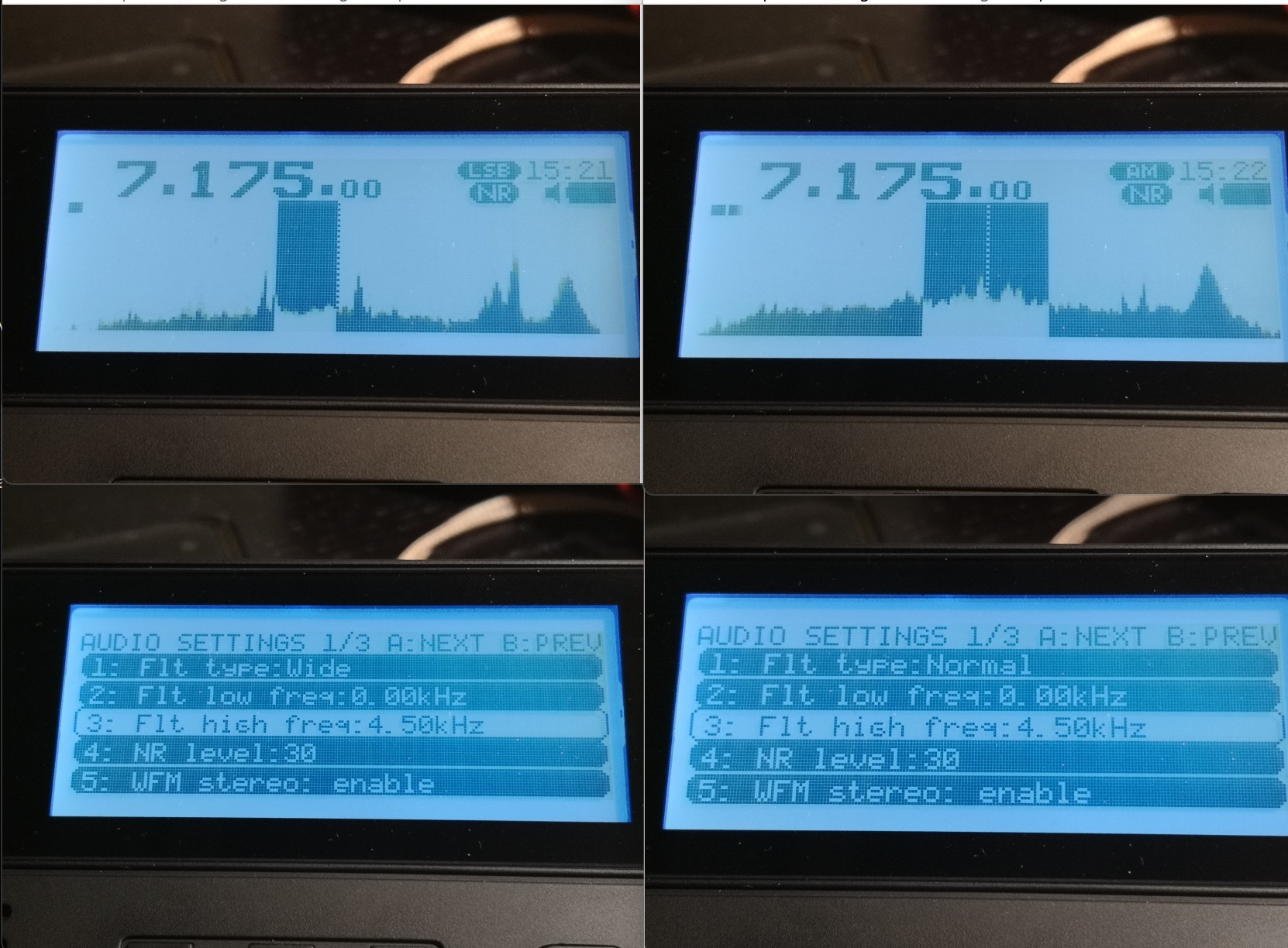
The [AUDIO] menu has 3 slots for your own filter settings named “narrow”, “normal” and “wide” and in each you can define low and a high cutoff frequencies, so that’s 3 variable filters so far. But of course, each mode has its own set of 3 “filters” you can define to your liking. The MLite-880 is one-upping this by giving AM and SAM, USB and LSB each an individual set of 3, too. WFM has 4, that’s 22 (!) places to set filter bandwidth. That’s not mandatory, of course, but still one nice source of confusion for elderly people like me and something to keep an eye on for a while.

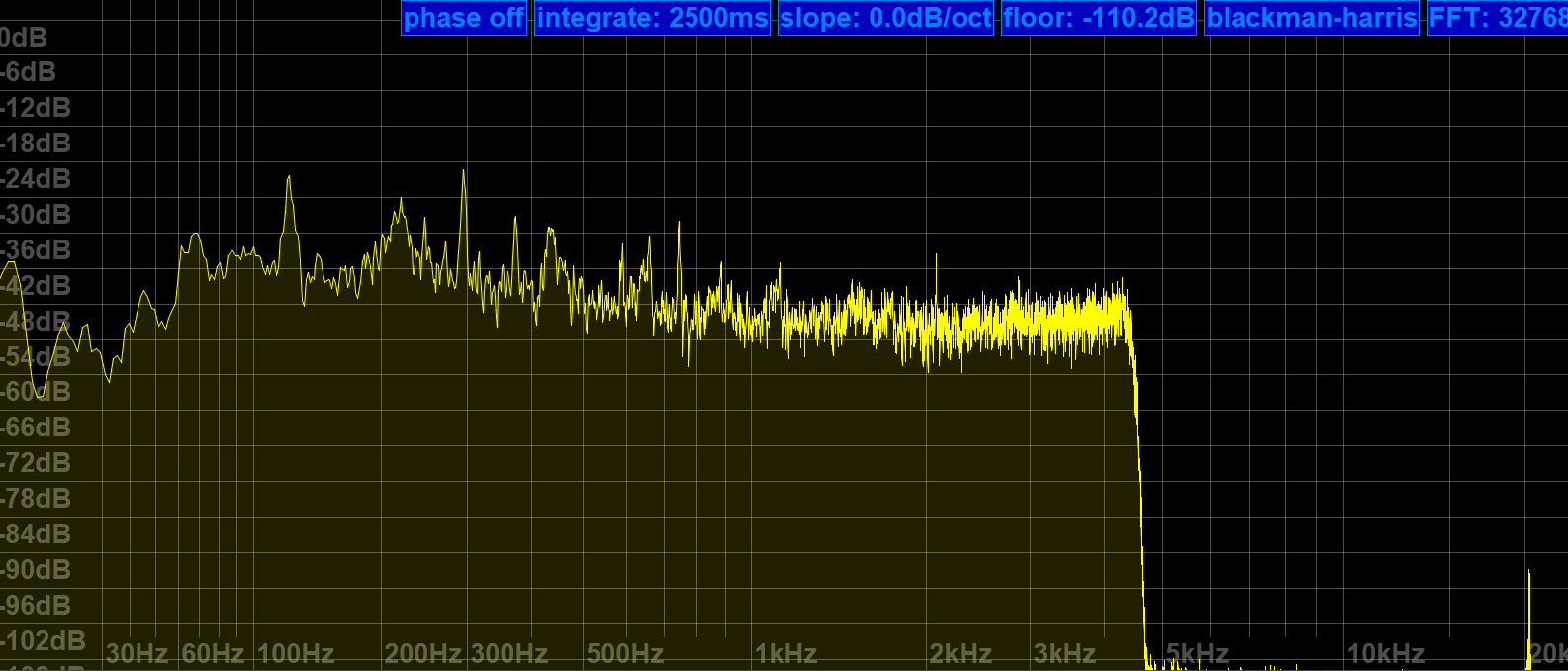
The filter shape itself is fixed, it has less rounded shoulders than what I have in the Belka and the IC-705 in “sharp” mode, with the same quality and perceived stopband rejection of those, and that alone would be enough to lift the long-term reception experience with the MLite way above and beyond the 473x chip radios, or even the best of their small analog ancestors from Japan.

Nice upper filter slope (lower filter frequency = 0) to claim all of a 9kHz ITU region 1 mediumwave channel and still keep the neighbors out.

25m band scan on a 10m vertical at the dike. It also demonstrates that the 4.5 kHz filter setting shown above is keeping the signals 10 kHz to each side of NHK on 11,625 kHz in check (NHK also received on 11,860 kHz, both direct from Yamata).

As for the mildly important question, what bandwidth is meant when you set the filters in AM – this is once again “per sideband” in AM, like on the Tecsuns: 4.5 kHz means 4.5 kHz audio bandwidth, the old-school physical IF ladder filter equivalent for that kind of passband would be labeled “9 kHz” if you want to compare that with some old rig. What sets this apart from e.g. my Icom is the possibility of having very wide sidebands up to 15 kHz for 30 kHz wide experimental AM broadcasts, also in SSB. The MLite reflects the IF filter equivalent in the width of the “dial pointer”:

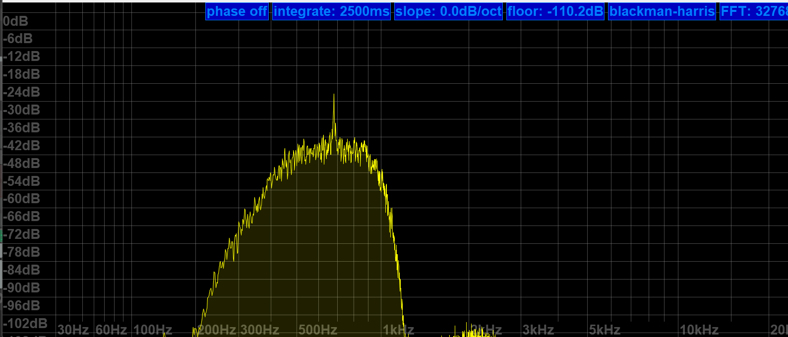
The properly narrow (>200Hz) and SNR-increasing CW filters are what make this ????? Trans-Okhotsk and the Belka the only receive-only portables with proper CW reception and a price tag around $200. Since FW 1.5, it also does CW “offset compensation”, so you don’t have to go through the hardships of subtracting your adjustable CW pitch frequency to correctly tune to a published frequency like in the Middle Ages anymore.

MLite 500Hz CW filter more or less centered at the CW signal at 700Hz

Frequency Calibration and Stability:

You can skip this section if you’re not much into SSB, and the following is not a complaint, just an observation and generally not a big deal, or rather part of the deal: The MLite-880 is not perfect <gasp> and it has “Lite” in the name for a reason:

Besides more obvious things, it lacks the automatic notch filter and the TCXO (temperature-compensated crystal oscillator) of the “big” Malahits. It has to make do with an XO and a lot of XOXO, and with that, it can’t quite match the linearity and temperature stability of the Belka, which is 99% on par with the IC-705. Most people are probably familiar with the need to calibrate their radios, and a few less have a radio that lets them do this, but not needing to do this is understandably one of the expectations people have with this SDR. But unlike the SW range, which is generally close enough to the nominal frequencies for most buyers, the separately calibrated VHF range seems to be in need of an initial calibration on many shipped radios; it was several kHz off in the VHF marine band on mine, too. I just tapped [3][5] and turned the knob until the station showed up right. Easy enough.

On shortwave, I’m talking about very small but occasionally inconvenient offsets/non-linearity in the tens of Hz range, nothing that makes you want to find your pocket calculator even if you’re a heavy SSB/utility listener. Calibration on digital receivers means you can fine-tune the master oscillator conveniently in a menu, and “non-linearity” means an offset varies over the course of the frequency range and does not plot a straight line. The offset is different in different bands, and you may or may not want to recalibrate there.

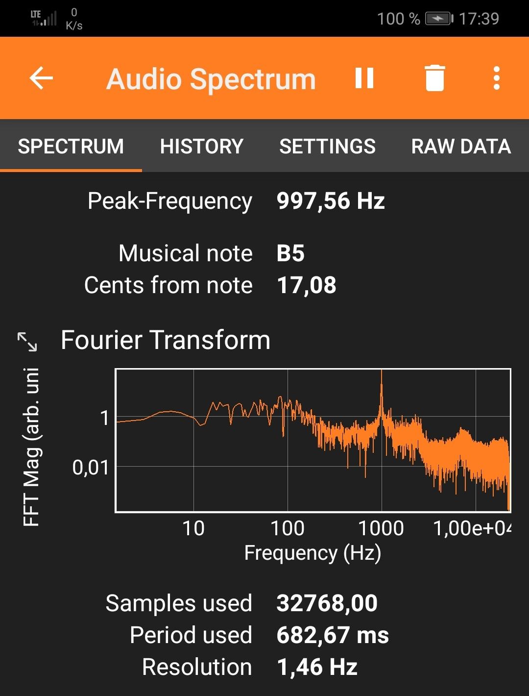
Calibration procedure (may not work on analog receivers!): Find a frequency standard station  (like WWV, BPM, or RWM) or just a regular station with no (or a published) offset. Tune 1kHz lower than this frequency and switch to USB to create a 1kHz het. Put that in a memory slot.  Tune 1kHz higher and switch to LSB to create a het again from the other side.  Now get your cellphone with a free spectrum analyzer app like Spectroid or Phyphox on it so you can easily measure the frequency of the het: It should be close to 1kHz in both USB and LSB. Starting technically at 27.000 MHz, the VHF range has its own calibration setting when you go there and you ideally want to find a calibration station near the top end of the range, like a 2m repeater or something.

For example, the needed offset on 5 MHz is -5 on my radio, on 10 MHz it’s +64, and +72 on 15 MHz at a cozy 25°C. That means I can calibrate for a negligible deviation in the 10 and 15 MHz signals and live with a somewhat bigger offset on 5 MHz, or I can make them all within +/- 30 Hz off, which is still awesome by analog radio standards and not terrible for a modern radio, but requires fine-tuning when you need it better than that. Calculating the indicated vs. actual offsets it dawned on me that the unit used on the shortwave side is still “x0.1ppm” and the math doesn’t math, that should read “x0.5ppm” as well.

The best I can get without 5MHz being off too much – good enough!

On top of the general offset, there’s also a noticeable (at 10-15°C differential) temperature drift, making the calibration efforts less persistent outside than I’d wish for. +72 for 15MHz at home to 120×0.5ppm at 15MHz equals 24Hz of temperature drift, adding to whatever offset was there before, which can amount to “too much” and there seems to be some “ripple” in the deviation curve: Here’s a recording of CHU on 14,670 kHz somehow ending 80Hz off right after calibrating the radio on 15 MHz:

Again, not great but not terrible in the grand scheme of things because deviations below 100 Hz are only ever a factor in SSB, and it may even add to the odd charme of this radio that it is very analog and old school within a tolerable margin in this regard.  But if you try ECSS reception with music, your ideal deviation is none and 10Hz at the end of “tolerable”.

Fixing the tuning emergencies when your fav song is playing and sounds terrible in SSB is done by dialing (think nine) [1][1], the useful number of the fine(st) tuning step in all modes, or just hit [3][5] and use the calibration function as “RIT” knob until it sounds right, and you will be good. It’s not a calibrated Rohdow & Shwartzkiy lab instrument, you can’t break anything, and it provides the needed fine resolution you’d need for true “zero-beating” but yes, it does feel very luxurious to switch to sideband when a $5 TCXO makes sure you can rely on the radio being spot-on in SSB when the station is, on any frequency, even in winter.

Synchronous Detector

…can’t be missing on a decent SW portable and this one seems to be a (non-selectable sideband) “PLL”-type detector and gives SDR-typical results: Remember that AM and SAM have individual filter settings so you want to make sure you match them when you compare that, but this detector is as unspectacular in a good way as it could be, it has super-solid lock and does absolutely nothing, zero, nada to the signal other than keeping the multipath distortion in check, which it seems to do very well.

31m band scan (antenna; car roof whip) with a brief demonstration of the sync detector at 0:16 seconds into the video. Note how the piano distorts when I turn it off again. Continue reading

Unlocking Rare DX Treasures with SDR-Console’s Powerful Data File Analyzer Tool

Finding Rare DX with the Data File Analyzer

By Don Moore

Don’s DX traveling stories can be found in his book Tales of a Vagabond DXer

I’ve been a real jack-of-all-trades in my over five decades of DXing. I began with SWBC (shortwave broadcast) but soon branched out to medium wave and voice utility. Later I added longwave beacons and more recently I’ve gotten into digital utility stations. My goal has always been to log lots of different stations from lots of different places. And the rarer they are, the better.

For SWBC and medium wave stations, as well as scheduled utility broadcasts such as marine and aeronautical weather reports, the DXing process is simple. You tune to a frequency at a time when a station is scheduled to be on the air. It’s either there or it’s not there. If it’s not there then maybe propagation isn’t right or maybe your antenna/receiver setup isn’t the best for that frequency band or the station’s power level. You tune away to find something else with plans to try again another day.

But it’s not always that easy. Most utility stations do not have fixed schedules and only come on as needed. The best example of that is two-way marine, aeronautical, and military voice communications.

In eastern North America, tune to 8906 kHz anytime from late afternoon until morning and set your receiver to USB mode. You’ll probably hear empty static at first but it’s unlikely that more than ten or fifteen minutes will pass before you’ve heard some aeronautical traffic. The frequency is assigned for communication on the North Atlantic and is heavily used by aircraft communicating with New York Radio, Gander Radio (Newfoundland, Canada), and Shanwick Radio (Shannon, Ireland). If you keep listening, the frequency will probably be occupied around 25% of the time. Wherever you are in the world, there are a few heavily used air frequencies like 8906 kHz and listening to them can be fascinating. But I want to log more than just a few easily heard stations.

Sticking to aeronautical DX, there are many assigned frequencies for different regions and air routes around the world. But propagation to those distant areas is unpredictable and less-used routes have fewer flights. Fewer flights mean less radio communication and more empty static. The most interesting frequencies may only see traffic a few times a week.

Hearing the rarest voice utility DX requires listening to lots of empty static just to get a brief DX catch. For years my process was simple. I would set my receiver to an interesting frequency and leave the tape recorder running while I sat nearby listening and doing something productive. I got some very good DX over the years that way. But I don’t want to think about how many long hours of empty static I listened to in order to get that DX.


SDRs offered some improvement. Instead of audibly monitoring a specific frequency I could now make a spectrum recording that included a band of interest, say the 8815 to 9040 aeronautical band. During playback I could visually monitor the SDR waterfall for interesting signals. That works. But watching an SDR waterfall scroll by for three or four hours gets tedious quickly.

(When I refer to SDRs, I mean ones consisting of a small box that is connected to and controlled from a computer using a software program. None of this applies to models such as the Malachite line or the Icom IC-R8600, which use SDR technology inside but mostly function as a traditional receiver.)

Finding a Better Way

That better way is, I think, one of the most exciting DX tools out there – the Data File Analyzer in the SDR-Console program. Since I learned about it a few years ago, the Analyzer has gotten me all kinds of catches that I probably wouldn’t have gotten otherwise. Let’s start with an overview and then dig into the how-to.

SDR-Console is one of the better-known SDR programs and it works well with most of the common SDR radios on the market, including the Airspy, Elad, Perseus, and SDR-Play models. Here’s what the main window looks like:

The Data File Analyzer is a second window that produces a scrollable waterfall display for the entire length of an SDR spectrum recording. The display is similar to a standard waterfall with frequencies along the bottom and times along the side. However, there is also a scroll bar on the right side for browsing through the entire length of the recording. Instead of watching a four-hour spectrum recording slowly roll by in real time, I can scroll through the window looking for DX.

And this is what makes the Data Analyzer really useful. When I spot an interesting signal, I click on it and that causes the main window to start playing at that time and frequency. Now going through a four-hour spectrum recording takes from a few minutes to around half an hour, depending on how much DX I find.

Here’s a closeup of part of that same screen of spectrum recording made on 24 October 2024 at a DXpedition in western Pennsylvania, USA.

“A” marks a short exchange between an aircraft and Ndjamena Radio in Chad on 8894 kHz. “B” is Niamey Radio in Niger on 8903 kHz. “C” is Gander Radio on 8891 kHz. Just to the left of that is a string of digital signals. “D” is New York Radio on 8918 kHz. Again, there is a string of digital signals just to the left. Finally, “E” is communication from Dakar Radio in Senegal and Sal Radio in the Cape Verde Islands on 8861 kHz. I caught four African aero stations in just four-and-a-half minutes. I could also show you long stretches of time when there was nothing interesting coming in. With the Data File Analyzer I was able to visually find and focus on the DX and not waste my time with the empty static.

Here’s another image taken at the same DXpedition. Notice the three transmissions between 8820 to 8845 that seem to be mirroring one other.

That turned out to be Flightwatch Brisbane, the Australian regional aeronautical network. It uses multiple transmitter sites on 8822, 8831, and 8843 kHz to cover the entire country. I had never logged it before and I doubt I would have found it if DXing in the traditional manner.

The How-To

Here I’m going to assume that you already have SDR-Console installed and know the basics of how to use it, including making spectrum recordings. (If not, see the links at the end.) This article was written using version 3.4 of SDR-Console. Some of the functionalities described are not in earlier versions, so upgrade if you are not up to date. And I should point out that while you can do this on a single monitor, it works more smoothly if you have a dual monitor setup and can put each window on a different screen. Continue reading

The Tecsun PL-990/PL-990x as an MP3 Player, Bluetooth Receiver, and PC Speaker

Many thanks to SWLing Post contributor, Bob Colegrove, who shares the following guest post:


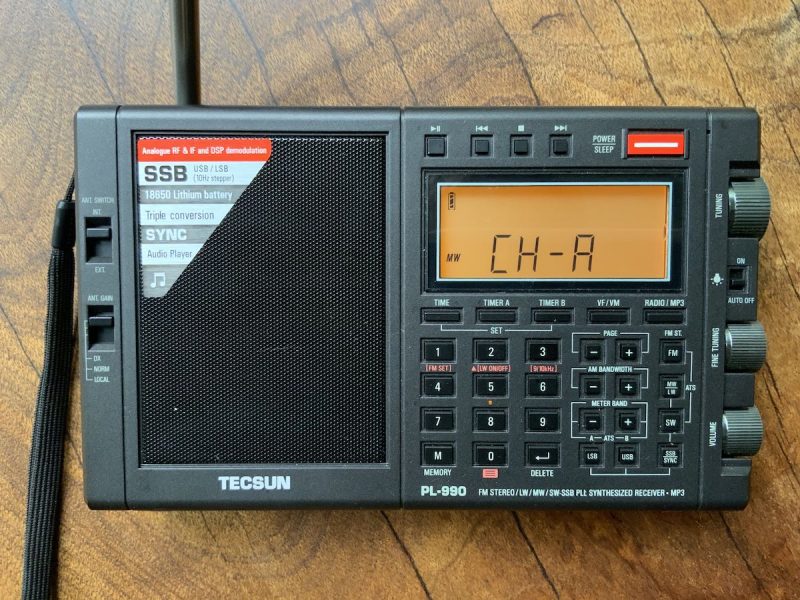
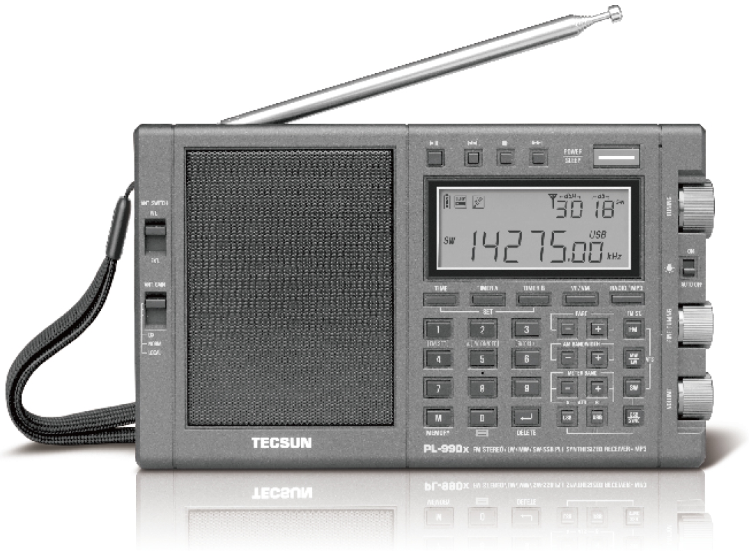
The Tecsun PL-990/PL-990x as an MP3 Player, Bluetooth Receiver, and PC Speaker

By Bob Colegrove

Source: PL-990x Operation Manual

Sometimes after a medium wave or shortwave DX session I just like to kick back and listen to good music.  Perhaps this is an age-related malady.  I recently did a scan of the FM band and came up with 60 listenable stations in my area.  By listenable, I only mean they can be received clearly.  In practice, I only listen to a couple stations.  Although, my tastes in music are quite varied, apparently, they do not coincide very well with local FM broadcast station formats.  No matter, I can still indulge myself listening to diverse favored artists.

The Tecsun PL-990/990x offers a ready solution having both an MP3 player and Bluetooth connectivity.  Actually, there are several compatible audio formats available on the player, but for simplicity I will merely refer to them as MP3.  I really didn’t buy this radio purposely for these additional features.  I bought it as a follow-on to the PL-880, which I still like very much for all its well-known features as a multiband radio.

I spent some time on the Internet reading all the reviews and watching many YouTube videos.  Among useful things, I learned how to take the radio out of its box.  The aggregate of all this information was thorough coverage of all the salient features of the 990 – all except the treatment of the MP3 player and Bluetooth connectivity.  These generally appeared at the end of each review in a by-the-way fashion with little detail.
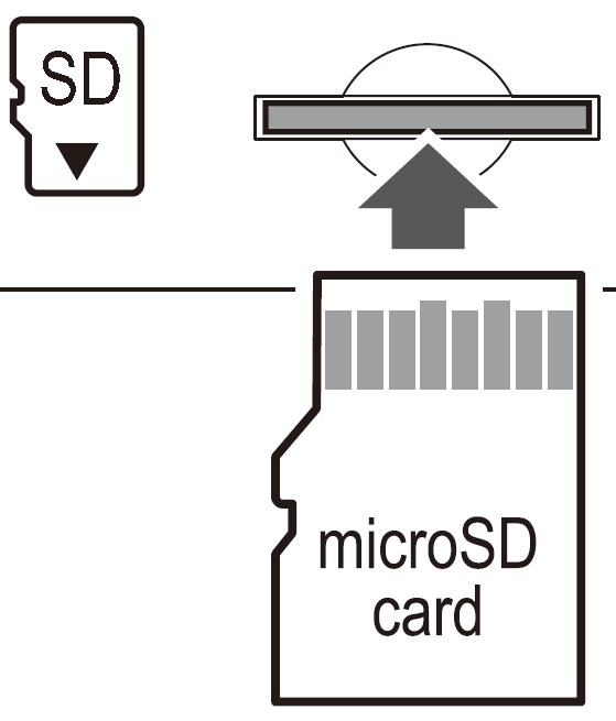
I bought a PL-990x with expectations that it would be a good radio performer, and that has proven to be the case.  During its setup and checkout, I realized the potential for its MP3 and Bluetooth capabilities.  A few years ago, I digitized all our vinyl recordings and cassette tapes, so I had many hours of material readily available for inclusion on a micro-SD card, which can be inserted on the bottom of the cabinet.

Source: PL-990x Operation Manual

The radio, MP3 player, and Bluetooth modes are available by toggling a single switch.

Source: PL-990x Operation Manual

As an MP3 Player

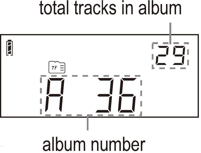
Unfortunately, the display does not have a multi-segment set of characters for text.  This is the way random RDS information is displayed on radios such as the XHDATA D-808 and Eton Elite Executive.  So, selecting albums and tracks on the 990 is limited to numeric representation, which doesn’t provide much of a clue identifying the musical selection.  The user must either remember where favorite files are stored by number or keep some sort of number-title log.

Files are stored on a micro-SD card having up to 128 GB in capacity.  That’s a lot of content.  The radio comes with a 16-GB card, which will probably be large enough for many users.  There are some details to consider when setting up the card.  This information is lacking in the manual, but I have tried to fill in the blanks below.

Some rules:

1. There is no purpose in trying to alphabetize or otherwise edit album or track titles to locate them in a specific sequence.  The 990 doesn’t understand this.

2. Generally, albums and tracks will be assigned numbers by the 990 in the order in which they are saved to the SD card by the computer.

3. Albums equal folders.  Tracks equal (MP3) files within each folder.  You can mix and match the content in albums and tracks any way you want to.  It does not have to conform to the publisher’s album content.

Source: PL-990x Operation Manual

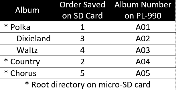
4. An album/folder can contain both its own tracks/files and nested folders containing other albums.  A nested album/folder will be numbered in sequence after the containing folder.  Any previously saved album/folders will be renumbered higher in sequence.

Rule 4 offers some flexibility.  You can come back later and prioritize any album/folder by simply nesting it with another album/folder.

The table below is an example of five different musical genres compiled into separate albums.  On the computer, the polka album was transferred to the SD card first, then classic country.  At that point, the polka album was A01 and country A02 on the 990 display.  Later, Dixieland and waltz albums were added to the tracks in the polka folder.  They then became A02 and A03 respectively, and the country album advanced to A04.  Finally, the chorus album was added in the root directory and became A05.

  • The 990 recognizes the SD card quickly after it is inserted into its slot.
  • The number of tracks and albums (files and folders) is only limited by the SD-card format, which for all practical purposes, won’t be a limitation.  By way of example, I used the default exFAT format and loaded an album with 657 tracks; I don’t recommend that many.
  • A single track can be repeated by long-pressing the PLAY/PAUSE button.
  • The tracks in an album will be repeated continuously.
  • There does not appear to be a way to shuffle tracks.

I did encounter some difficulty with micro-SD card compatibility, which was independent of brand.  A couple micro-SD cards were prepared on a computer using an adapter card and a micro-SD card reader and operated correctly in the computer, but the content was not recognized by the 990.  I suspect this might be due to the early manufacture of the cards, but I’m not sure.

The 990 manual picks up the explanation from there describing operation of the control keys.  I found it most convenient just to scroll through the albums with the FINE TUNING knob and through the tracks with the main TUNING knob.  The number pad buttons will also work for direct album or track selection.  Their application depends on the last tuning knob turned.

Bluetooth

Bluetooth is a hidden feature of the 990.  Activation is partially covered on the hidden feature sheet.

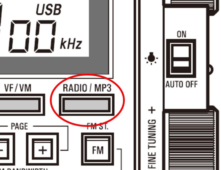
  1. With the radio off, press and hold the PLAY/MP3 button.  If OFF (for Bluetooth) appears in the display, press and hold the button again until ON appears in the display.
  2. Turn on the radio.
  3. Toggle the PLAY/MP3 button until “BT” appears in the display.  The display will have a horizontal, animated dashed line for a few seconds, then it will change to an animated rectangle indicating that the Bluetooth feature is on.
  4. Follow the procedure for your tablet, computer or phone to pair the device with the 990.  “Tecsun PL-990” should appear on the device as a choice for pairing.  The 990 only pairs with one device at a time.  If you have trouble, ensure that the 990 has not inadvertently paired with another device.

Bluetooth, of course, opens Internet streaming from a phone, tablet or computer.  These ‘remotes’ have the convenience of full text capability and offer easier selection of content.  I paired my PL-990x with a Kindle tablet; it has a range of at least 25 feet.  The same micro-SD card could in theory be transferred from the radio to the tablet and function the same way.  A smart phone would add cellular connectivity.

Control:

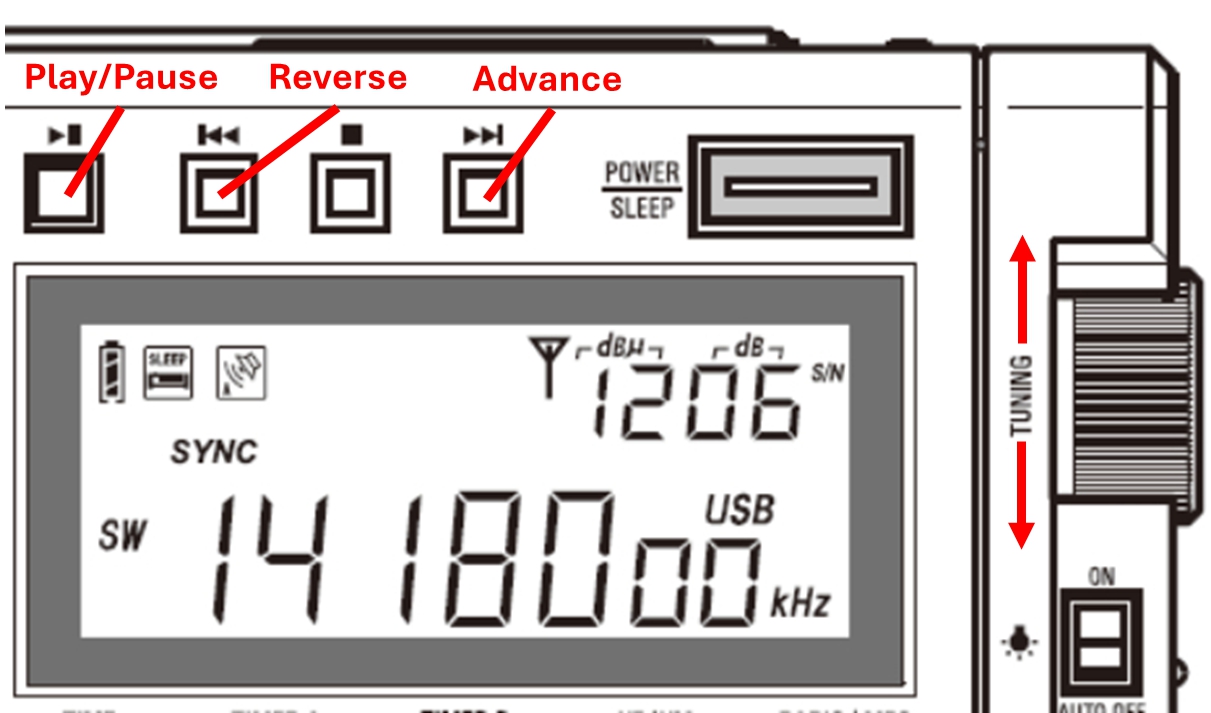
Three of the four player control buttons above the display are active in Bluetooth.  The stop button has no effect.  As with the MP3 player, the main TUNING and FINE TUNING knobs will also advance or reverse the track selection.  Interestingly, this works with audio player apps as well as services such as YouTube, where it advances or reverses videos on the tablet, computer or phone.  In addition to the RADIO/MP3 button, pressing any of the band buttons will immediately exit Bluetooth and tune to the selected radio band.

Source: PL-990x Operation Manual

In MP3 or Bluetooth mode, there is no noise from a USB wall wart.  It might be a good time to charge the battery.

As a Computer Speaker

Finally, there is what the 990 manual calls the computer speaker mode.  Sounds inconsequential.  Why would anyone want to use a monaural radio on a computer that’s likely outfitted with stereo speakers?  Actually, it’s more than that.  By plugging your 990 into a USB port on your computer you have the normal charging feature, but you will also have complete USB connectivity with your PC.

Turn on the 990.  You may have to press RADIO/MP3 button until “PC” appears in the PL-990 display.

  • You will not be able to use the radio.
  • The content of the micro-SD card in the 990 should appear as a USB drive in the computer’s file directory.  You can transfer files on or off the 990, but the process will be very slow.  Transfers from the computer to the 990-installed SD card follow the same rules listed above for the MP3 player.
  • The computer will provide the MP3 play function through its own app.  You can select files from either the 990 SD card or those on the PC and play them through the 990 speaker.
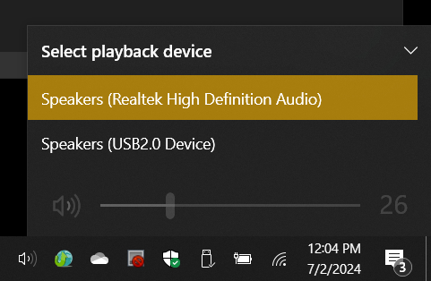
  • You can switch speakers between the 990 or those on the computer by selecting the speaker icon on the computer task bar, then selecting the available speakers.

  • The pause/play button on the player controls will work, but the reverse, stop, and advance buttons will not.

Final Thoughts

Some disappointment was registered in the reviews that the 990 does not have a recorder.  Yes, this would have been nice.  One thing it does have is a line out jack which has adjustable gain.  This makes my outboard recorder much happier than when it is used with some other radios.

Since we are talking about audio, I have noted that some reviewers still prefer the sound of the PL-880.  To my ears, the 990 sounds every bit as good.  Remember, these are mid-size portable radios.

The inclusion of MP3 player and Bluetooth capabilities on the 990 adds very useful functionality to this radio.  After nearly four years of consumer availability, I must wonder why they haven’t received more attention.

D.I.C.A.: Giuseppe’s latest homebrew portable antenna

Many thanks to SWLing Post contributor, Giuseppe Morlè, who shares the following antenna project:

Dear Thomas and SWLing Post Friends ,

I’m Giuseppe Morlè, iz0gzw, from Central Italy, Formia on the Tyrrhenian Sea…
Some time ago I had drawn this minimal HF antenna on paper…

I took advantage of the New Year’s Eve rain to be able to build it with the usual leftover scraps…

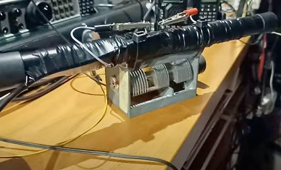
The system consists of a 35 cm tube with two separate windings of telephone cable on it, 2.5 m on each side, green and white…in the center I connected the 4 ends to X…

The green lead with the white and the white with the green to the variable capacitor and the other two leads to the RG58 cable that goes to the receiver.

I started the test and noticed that the agreement was possible from 7 to 21 MHz…

I then placed a long ferrite inside the tube…

I noticed a strengthening of the signal and consequently of the noise picked up and the chord dropped to 3.2 MHz.

Tests inside my shack showed decent reception on all ranges…in the evening on the balcony on 80 m. I could perfectly listen to a QSO between Italian stations.

Everything is still in the experimental phase and I think I will try this minimal system also in QRP transmission.

In this first video I explain how this minimal antenna is made:

The second video concerns a 20 meter test by car. The antenna is placed on the dashboard of the car inside:

In the third video, I explain how it works without the ferrite and with the ferrite inside the tube:

In this video you can see the test on 40 m. outdoors on the roof of the house:

The tests are carried out at home in order to understand what can be achieved in an environment that is difficult to receive.

I will do more outdoor tests and I think this small minimal antenna will receive better. I will keep you informed.

Thank you all for your attention and I wish you all a new year full of satisfaction.

’73 de Giuseppe iz0gzw.

Fascinating, Giuseppe! I love all of these brilliant little antennas you design out of your “junk” drawer! We look forward to hearing more about this antenna and any modifications you make to it!

TomL’s Guide to Audio Plugins For Radios: Part 2 – SDR Recording

Many thanks to SWLing Post contributor, TomL, who shares the following guest post. Click here to check out all of the posts in this Audio Plugin series:


Audio Plugins For Radios, Part 2 – SDR Recording

by TomL

I started investigating using the old Kenwood transceiver to send audio to my laptop and process the receive audio using VST Host for a number of functions: Noise reduction, Equalization, reduce Sibilances and fading distortion, increase presence of vocals without sounding boxy, etc.  It was a qualified success depending on what VST apps I used, in what order they were used, and what settings each of them were set to.  In this episode of ongoing discovery, I will attempt to show how easy it is to OVER-process the shortwave broadcast audio plus comparisons to my regular Audacity post-recording treatment.

Audio Examples

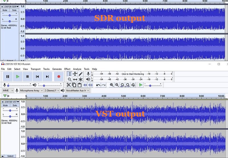
I noticed for the first time that the SDR creates a somewhat compressed file which can be seen when comparing the Waveforms of SDR vs. VST Host output files.  This means that the unprocessed SDR file will always appear to sound louder because of this compression.  This loss of Dynamic Range makes it harder to do the comparison.  Therefore, the Audacity-only examples below are reduced 3dB or 5dB to maintain apparent loudness.

Example 1:  KBS Weekend Playlist – S6-S9 signal, somewhat severe fading and moderate polar flutter.

SDR Console 3.2 using my usual NR4 set to 2dB Reduction, 30% Smoothing, and 3dB Rescale plus a Blackman-Harris-7, 5.3 kHz filter.

AUDACITY file is using my usual Audacity noise reduction:

VST version 2: Used my first set of VST apps.  Sounds harsh with hash-noise and overdriven:

VST version 3: Used way too much bass, too much grunge, attenuated highs, still overdriven:

VST version 4: Using a different order to the Denoiser apps, added in Modern Exciter app, cut back on some bass but still too much, and overly forward sounding midrange:

VST version 5: My current Baseline setup.  Adjusted the Denoiser apps, less extreme bass & treble, adjusted the De-Esser app, set the midrange to be less forward with just a single setting:

To my ears, Audacity processing is nice but as discovered before, sounds compressed and does not reduce some of the other problems inherent in shortwave signal fading and loss of musicality.  It sounds utilitarian.  Also, the noise is a bit more gnarly.

Versions 2-5 go through iterations of listening to the exact same segment over and over (and over) and trying different VST apps and settings.  I think my comments are mostly accurate next to each version.  However, you may think differently and perhaps prefer the sound of one of the other versions?

Example 2: Encore Classical Music, WRMI (fading S9 signal) – Audacity vs. Version 5 VST settings.  VST is quieter and sounds less harsh than the Audacity version.  A generally more smooth sound.


Example 3: RCI in Russian, S7-S9 with moderate polar flutter – 7kHz filter in SDR Console but VST Host is using BritPre, an analog preamp using a 6 kHz low pass filter to try to reduce DSP filter “ringing”.  It shows some interesting possibilities.

Example 4: RCI in Russian – Music from the same broadcast and VST Host setup in Example 3.  The screeching flute is under more control and strings more defined in the VST version.

Conclusions

I like the results of the audio processing that eventually ended up with “version 5” (plus the possibilities at 7kHz, too).  It is not Earth-shattering but is an incremental improvement in my opinion (there is always room for improvement).  I can use it in a simple Workflow anytime I want to record something off of the SDR.  Also, I had already been using Voicemeeter Pro, a software audio mixer.  It is setup with different profiles to do SDR, Ham, FM Broadcast, and now, VST Host audio routing.  This process took a long time but seems satisfactory to use as a Baseline setup, which then can be tweaked slightly depending on various types of audio coming from the SDR.  These changes in VST Host can be stored as their own unique profiles for audio processing.

However, a word of warning!  Messing with Windows audio Sound settings and mixer software is potentially a confusing process and one can easily end up with a spaghetti-pile of conflicting connections, no audio output, doubled echo output, distortion, way too loud, way too soft, etc.  If you start this experimentation, make sure to write down your current Windows Sound settings, both the Playback and the Recording settings for each item listed.

Having an SDR radio + Voicemeeter + VST Host is a very flexible setup.  I can now safely say that the only thing I need Audacity for is to Normalize the peak audio to the -1 dB broadcast standard volume, which is a HUGE time saver.  The SDR Console IQ files can be scheduled and processed from there at a later time.  Also, the use of Voicemeeter Pro allows me to switch when to use VST Host anytime I feel like it, and Voicemeeter Pro comes with its own (manually engaged) Recorder.

Part 3 of this series will discuss Technical details for my setup.  Your setup may need different settings or you may find a better way than I did.  This will take some dedicated time.

Happy Listening and 73’s,

TomL

Click here to follow all of the articles in TomL’s audio plugin series.

TomL’s Guide to Using Computer Audio PlugIns with Older Radios

Many thanks to SWLing Post contributor, TomL, who shares the following guest post:


Using Computer Audio PlugIns with Older Radios

by TomL

Older radios have a way to get audio out to speakers or another audio input device, usually just a headphone jack.  Software for processing audio are plentiful and very useful tools, called VST’s.  Furthermore, most Plugins were made for Musicians needing full frequency spectrum capability.  I will use my Kenwood TS-590S amateur radio as a test case.  I have used its speaker output to a cheap Behringer UCA-202 RCA to USB converter (it has its own volume control to keep it from overloading).

Amazon Link: Behringer UCA202

My Windows 10 Sounds Properties sees this audio as “3-USB Audio CODEC” which I have enabled on a physical USB hub with individual power switches for each port.  Thanks to Steve (K1GMM) and his YouTube channel (K1GMM Green Mountain Maniac) for describing how to use Windows plugins for processing either Receive or Transmit audio.  This article only focuses on Receive audio.

For my simpler needs, I have chosen to use VST Host.  It will run the small “apps” that usually have a file extension of .VST or .DLL.  I downloaded it right from Steve’s website:

https://kc1egu.wixsite.com/essb-ham-radio/copy-of-icom-ic7300-others

I then downloaded a number of plugins suggested by Steve on his web site (“More” Menu pulldown, DAW’s/VST DOWNLOADS).  Each VST file can be copied to a central directory/folder on your computer and all read from the same place inside the VST Host.  Most of these are Windows types but there are some for Linux if that is something you use.  I found that VST Host does NOT like a write- protected directory, so it and the VST’s reside in my top-level Documents directory.

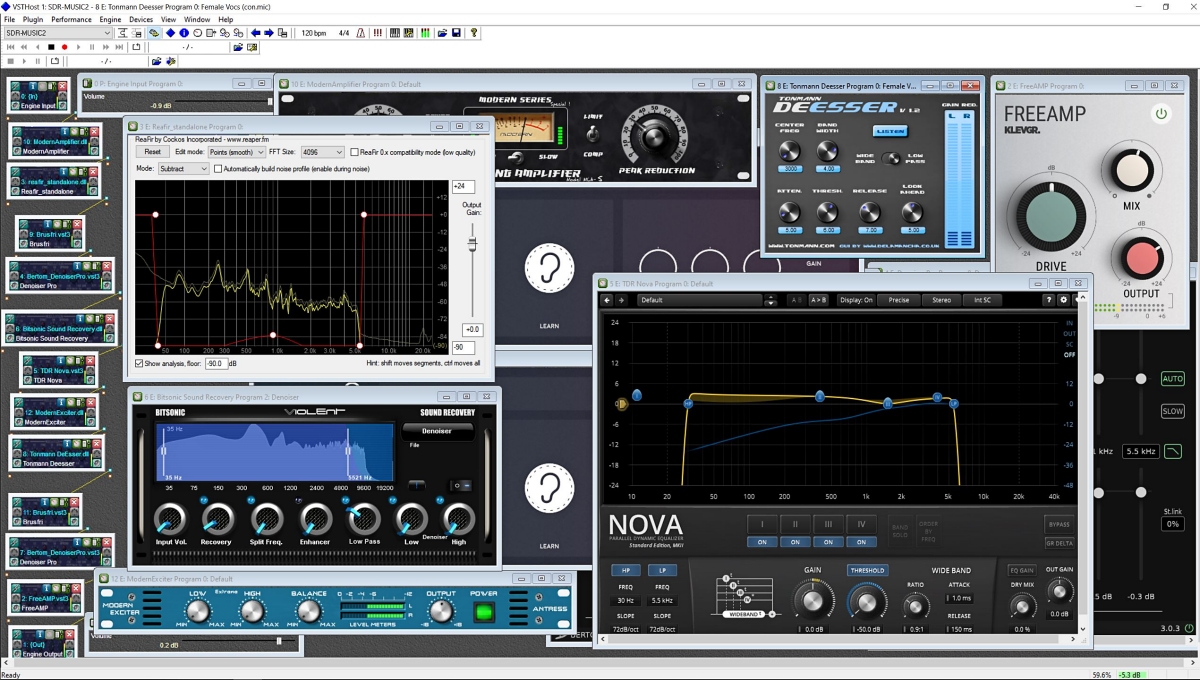
My resulting “chain” of VST’s process the audio from my 3-USB Audio CODEC in a sequential manner, which are:

  • ModernAmplifier (a Limiter to keep strong signals from overloading the processing)
  • ReaFir (an interesting “Subtract” feature where I cut down on the “roar” around 800-1200 Hz)
  • Bertom Denoiser Pro (EXCELLENT static & background noise reducer)
  • TDR Nova (a powerful, well-made Compessor & DynamicEQ combo)
  • Sennheiser-AMBEO-Orbit (a Binaural soundscape).

Once VST Host is installed, create a separate folder for the VST files.  Now just copy the VST3 or DLL file for each of the apps downloaded like the ones I list above.  If you have a 32-bit version of Windows, you will have to use the VST’s that are 32-bit, not 64-bit.

In VST Host, set the Wave Input and Output and sampling rate (Menu: Devices—Wave).  In my case it is the aforementioned 3-USB Audio CODEC for (Microphone) Input Port and VoiceMeeter Aux-Input for the Output Port.  The sampling rate is set to 48000  (You can choose Output to your “Default Speakers” which should be in the list if you do not use an extra mixer software like I do).

Now, go to Menu: File, Plugins and load each plugin that you want to use.  The VST3 or DLL files should all be in the same directory that you made earlier.  You may have to tell VST Host where to find them by setting the Plugin Path (Menu: File, Set Plugin Path…).

Now, once you have all the VST apps opened, you will notice that all of their individual outputs go directly to the VST Host Output.  Not good, since your computer will not have enough cores to parallel-process all of these apps at the same time.  So, Unchain them all by right-clicking on each app and choosing “Unchain”.

Now you will see all of the yellow connecting lines gone.  Arrange (click/drag) each app in sequential order on the screen.  Starting from the bottom up, right click on the app just above VST Output and choose Chain After…

Repeat up the chain, choosing the one above it to Chain After until you are left with a Daisy-Chain of apps, each output going to the Input of the next app in your desired order of processing:

Now turn on the radio to get audio going through the chain of apps.  Tweaking each app is part of the tedious process of learning if an app will help or not.  Just replace and Chain After in the order you want with other VST apps that you find more helpful.  Tinkering with this should yield some satisfactory results if you do not overdo applying features in each app.  To save the layout and VST settings, go to Menu: Performance, Save As and give it a name to store in the data file shown (just a name since it will put it into the default line 000 for you).  You can choose this in future sessions from the main pulldown Menu below File. (Note: It is called “Performance” because this stuff was written for Musicians to save their home studio music along with the settings for shaping the music tracks; 99% of planet earth calls this a “Layout”, a la, Microsoft Office)

Here are two examples of sound from the radio without processing and then adding in each app over a few seconds.

LZ1AA from Bulgaria. Processing 10 secs., off 15 secs., on again 8 secs.


CHU Canada. Processing on, space, processing off. Notice a little “water” effect since AM Broadcast needs quite different settings compared to SSB Ham Radio.

You can check out Steve’s “Green Mountain Maniac” YouTube channel and see for yourself what can be done with sound processing for Radio.  Some of his techniques can be used with old shortwave radio receivers as long as it has a working headphone jack or AUX Out jack:

K1GMM-RXDAP VST HOST YouTube video

Cheers and Happy Listening,

TomL

Tom’s Recommendations: Earbuds and EQ Settings for Shortwave Listening

Many thanks to SWLing Post contributor, TomL, who shares the following guest post:


Earbuds for Shortwave Listening

by TomL

A few years ago I had bought the discontinued Sennheiser MM 50 earbuds for a cheap price on Amazon to use in my various radios.  The portable radios in particular can use more fidelity because of their small, raspy speakers.  I also like to listen without bothering others around me who might not want to listen.  And earbuds are a LOT more comfortable for my ear lobes than any over-the-ear headphones I have ever used.  Furthermore, the old Apple iPhone 4 earbuds were very harsh to listen to.  However, a trade-off is that, generally, earbuds are somewhat fragile; one of the two pairs of MM50’s died through mishandling.

I was generally happy with them while listening to Shortwave broadcasters with a mix of news/talk and music.  I especially liked them on Mediumwave listening; stations can sound surprisingly good when playing music.  Then I tried using these earbuds on my Amateur Radio transceiver, a Kenwood TS-590S.  I was impressed how clear they sounded with a lack of distortion, although there was too much bass.  Fortunately, Kenwood supplies USB connected software with an TX & RX 18 band EQ (300 Hz spacing, not octaves).

Here is a frequency response chart I found from Reviewed.com for this model:

One of the notable things about these earbuds is the total lack of distortion.  Most likely one of the reasons they sound so clear on Shortwave, which has many LOUD audio spikes.

I had not wanted to get Bluetooth earbuds.  However, I had recently upgraded my cell phone and NO headphone jacks anymore!  So, while I do not use Bluetooth yet for radios, I can see a time in the future to get a Bluetooth transmitter to plug into a radio with a headphone jack.  I am reluctant since I do not like having to recharge my earbuds and I put in a lot of radio listening time.  Am I supposed to buy two Bluetooth earbuds and swap while charging?  Maybe in the future.  And also, am I supposed to buy a Bluetooth transmitter for every non-Bluetooth radio I own?  Not likely gonna happen.

In the meantime, I ordered cheap wired earbuds from Amazon.  I had a $5 credit for trying Prime, so when I saw these Panasonic ErgoFit wired earbuds (RP-HJE120-K) for slightly over $10, I said to myself, “why not?”.   Supposedly wildly popular, they are one of the most rated products on all of Amazon with 133,821 ratings/opinions (perhaps Russian bots?!?!?).

Here is a frequency response chart from ThePhonograph.com for these Panasonic earbuds:

You can see comparatively that the bass response in the very good Sennheiser MM50’s is much stronger, being good music earbuds.  But for voice articulation, not as much, even though they have no distortion.  The Panasonic ErgoFit’s have more modest bass, less of a dip in the lower midrange audio frequencies, and more importantly, has a peak near 2500 Hz and its harmonic 5000 Hz.  The highest highs are also modest compared to the Sennheiser model.  This general frequency response to “recess” the bass and treble frequencies and peak the 2500 Hz is very useful for voice intelligibility.

As described by the famous speaker-microphone-sound-system maker, Bob Heil relates what he learned from the scientists at Bell Labs many years ago.  Speech intelligibility is enhanced when audio is compensated for our natural human hearing.  Equalizing below 160 Hz, reducing the 600-900 Hz region, and peaking the 2000-3000 region centered at 2500 Hz will increase intelligibility dramatically.  The story goes that Bell Labs was tasked by parent AT&T with finding out why the earliest phones in the 1920’s sounded so muffled and hard to understand.  After many experiments, the scientists found the most important frequencies for our ears + brain to comprehend speech.  In other words, our ears are not “EQ-flat” like a scientific instrument is. Continue reading