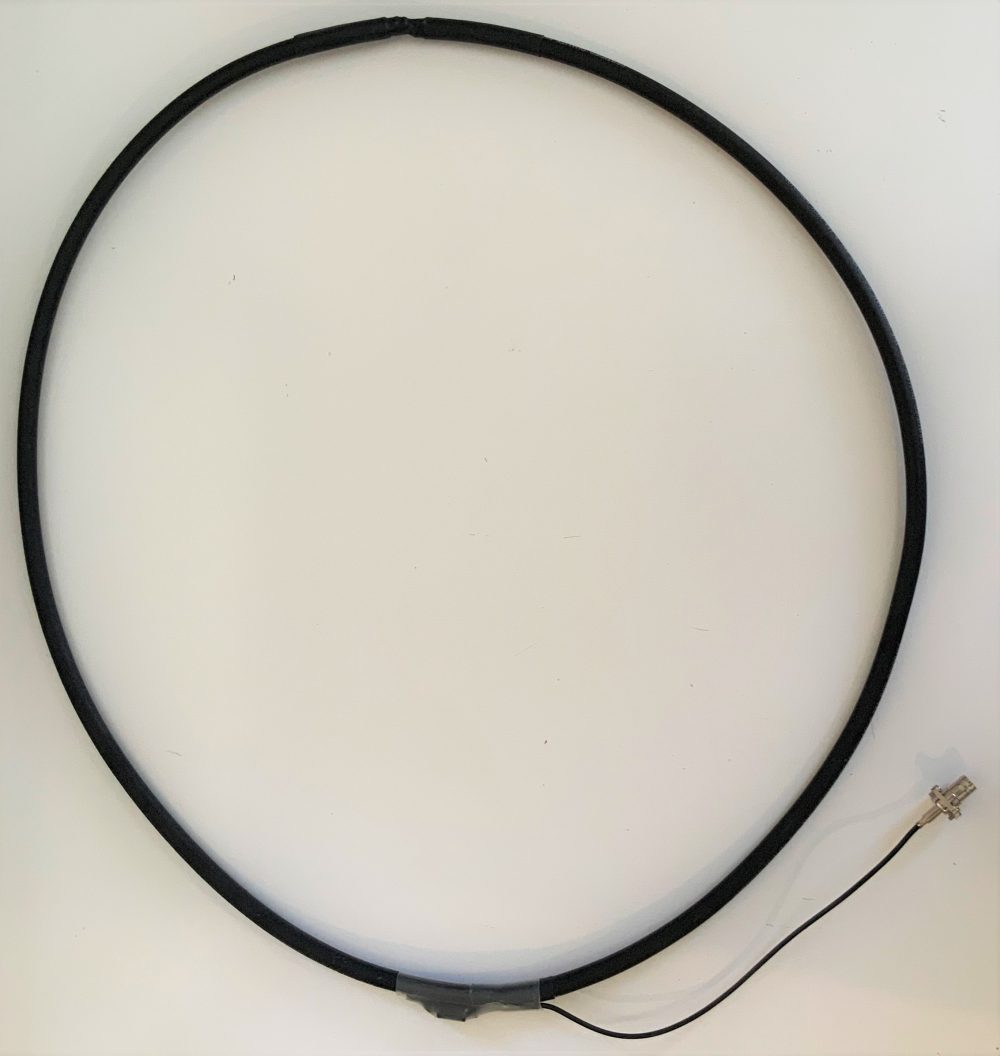
 Many thanks to SWLing Post contributor extraordinaire, 13dka, who brings us Part Two of a three part series about the new SULA homebrew antenna project. This first article describes this affordable antenna and demonstrates its unique reception properties. The second article focuses on construction notes. This third and final article will essentially be a Q&A about the SULA antenna.
This wideband unidirectional antenna is an outstanding and innovative development for the portable DXer. I love the fact that it came to fruition via a collaboration between Grayhat and 13dka: two amazing gents and radio ambassadors on our SWLing.net discussion board and here on the SWLing Post. So many thanks to both of them!
Please enjoy and share Part 3:
Part 3: SULA Q&A
by 13dka
Q: Where can I ask questions, discuss all aspects of the the SULA or collaborate in its further development?
A: There is a thread dedicated to the SULA in the new SWLing.com message board: https://swling.net/viewtopic.php?t=55

Q: Since the antenna is “lossy”, what’s the point of having a “beam”?
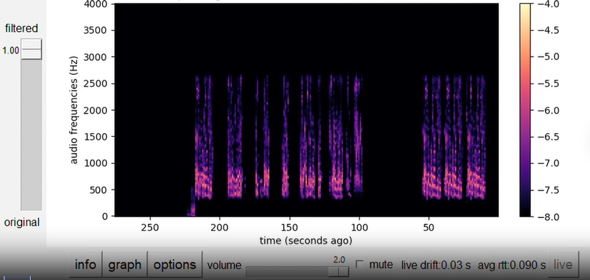
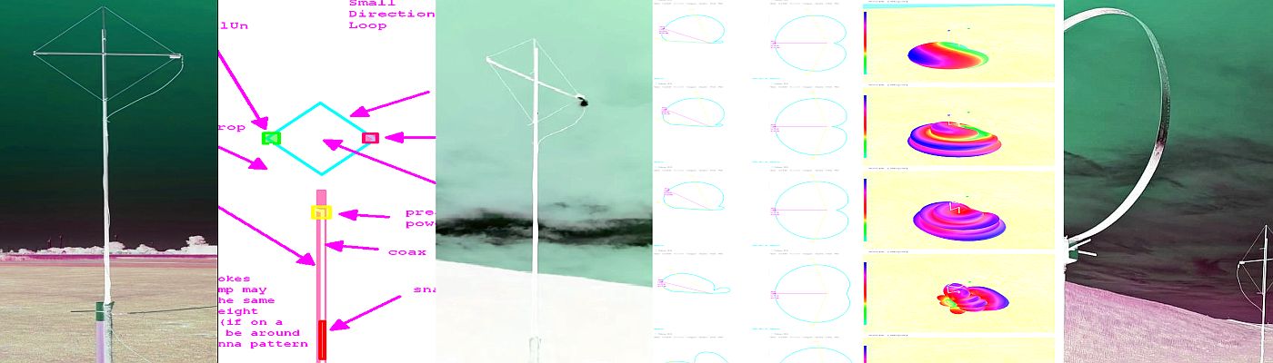
A: The answer is once again “SNR”: First off, remember that the LNA is there to make up for most of the losses. Secondly, this is all about the noise pickup, 20dB less gain/more losses outside the main lobe means also a reduction of atmospheric/cosmic/whatnot QRN and of course everything manmade from all these sides. The wide horizontal lobe is more or less one hemisphere horizontally, but the flat-ish vertical pattern makes that only a slice of it. In other words, there will be less QRN and QRM pickup from the back and the top. The idea is that the SNR will ideally increase more than the preamp’s noise figure will cost and it often sounds like this is what actually happens. Of course it’s also nice that you can turn an unwanted signal down using the more or less pronounced notch in the backside pattern up to 21 MHz – also very helpful for direction finding.
Q: Do I need a rotor?
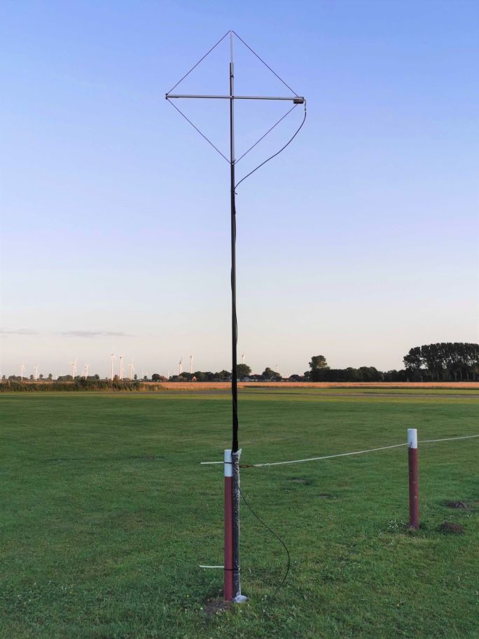
A: It depends. If you are one of the lucky few still having a low-QRM-environment at home and you want to put it in the backyard, you really may want to be able to turn it remotely. If you’re using it portable you can simply rotate the mast manually. If you have local QRM or can’t mount it very far away from your or other houses, you may want to rotate the back of the antenna towards that source, leave it at that position forever and enjoy what’s coming in on the pretty wide main lobe of the antenna. The horizontal lobe covers more or less half of the horizon, depending on your stations of interest and location you could get away with never turning the antenna at all.
Q: Is it better than the XYZ loop?
A: Hey, that’s exactly what I wanted to ask you! 🙂 Even though the SULA is very similar in appearance and performance to a good SML working in ideal (ground conductivity) conditions, the SULA is a pretty different animal with a different behavior: Regular small loops, besides being bidirectional, can lose quite a bit of their low angle sensitivity over “poor” ground while the SULA is supposed to be retaining its properties better over any type of ground. Also, while many SMLs are tuned for VLF through the lower portion of the shortwave, the SULA complements those with quite uniform (good) properties up to 30 MHz and beyond.
Q: I have an end-fed random wire or dipole strung up from the house to a tree etc. – can the SULA beat that?
A: That’s quite possible. To get low takeoff angles from horizontal wire antennas you need to string them up at least 1/2 wavelength high, that’s 20m/66ft on 40/41m, 10m/33ft on 20m and so on. If you can’t do that, the SULA may be your ticket to listen farther beyond the horizon. Also, wire antennas are often strung up to match space restrictions or avoid QRM vectors and that way you may end up with some directionality in directions you don’t want, or no directionality at all when the wire is too low. Another noteworthy point is the ground: For most horizontal antennas, better ground means a considerable higher takeoff angle so the dipole needs even more height for low angles. The SULA’s takeoff angle benefits a little from the better ground and only gets a little worse over poor ground.
Q: Do I really need an LNA?
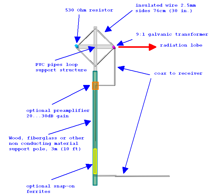
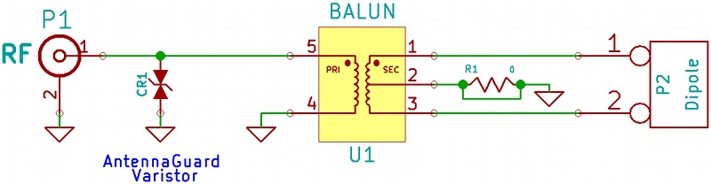
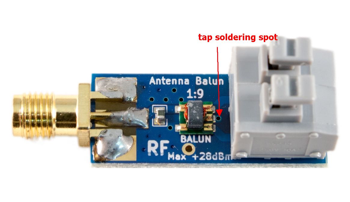
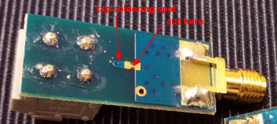
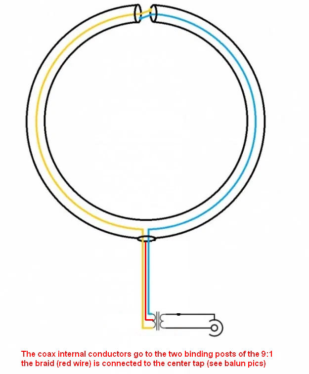
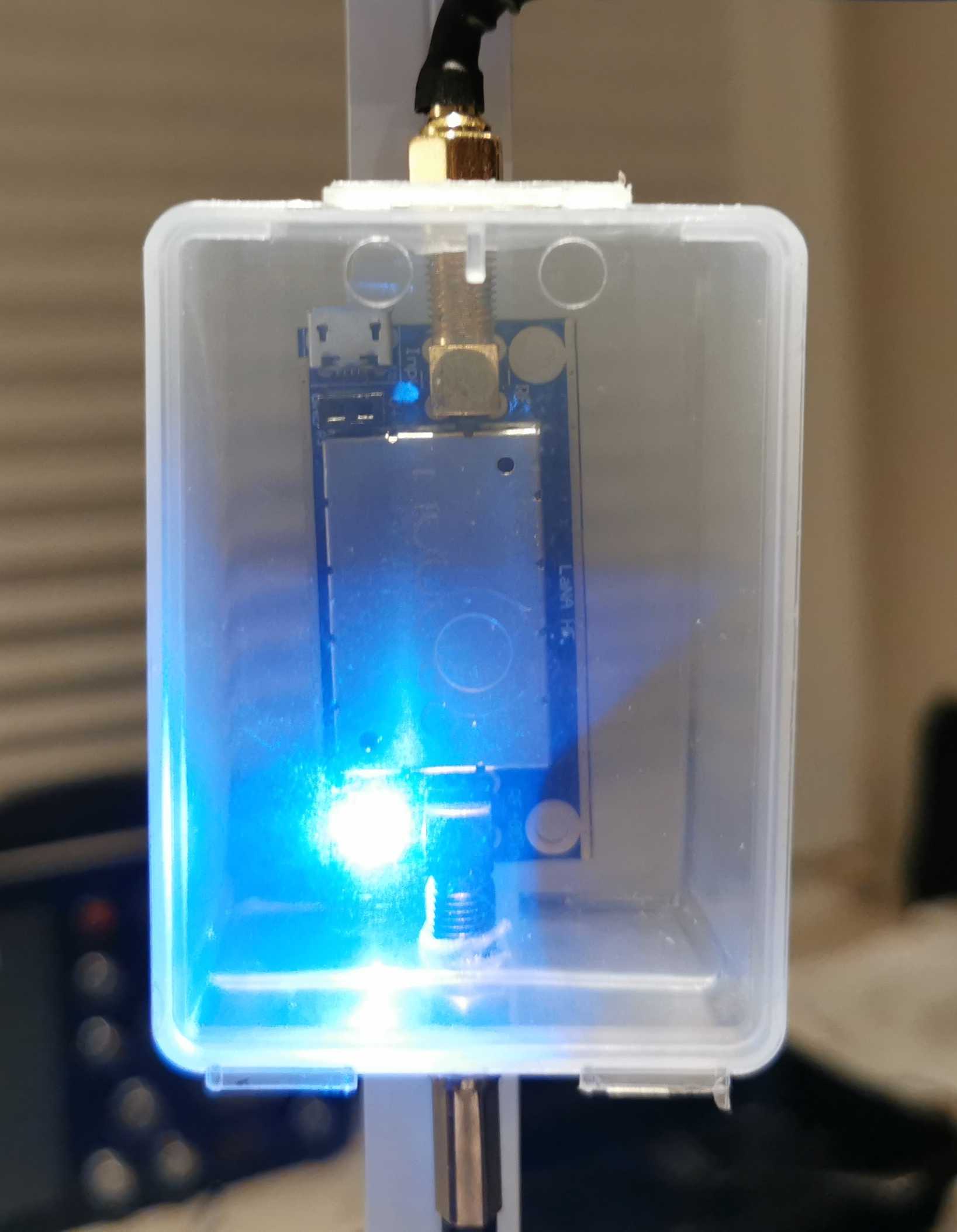
A: I hope so? Of course it depends… if you are going to try this antenna in a very noisy environment, the LNA may have little to no benefit. The noise is limiting your “radio horizon” to very loud signals anyway and for those you may not need an LNA, ever. On the other hand, the antenna is very lossy and in a quiet environment where noise is not an issue at all, weak signals may drop below the sensitivity threshold of your receiver without the LNA. The less noise you have, the more you’ll be able to benefit from an LNA. You will also need one when your radio isn’t all that sensitive, similar to the requirements to run a YouLoop. Andrew kept the loop impedance as constant as possible in order to allow any low impedance coax preamp to work behind the Balun. Any LNA with 20dB of gain should do, as per usual, better stuff may bring better results.
Among the sparse offers for decent shortwave LNAs, the NooElec LANA HF seems to be the only decent LNA sold via Amazon. It’s comparatively low-cost and unlike the other offers on Amazon, ready to be powered via Bias-T or even via Micro-USB and therefore happy with 5V. Since I also had the balun from the same company I could simply connect that all with a couple of these cute little SMA plumbing bits and it worked. The downside is its unknown but perceivably low resilience against intermodulation (low 3rd-order intercept point), this is usually not a problem with such a small loop but it can be in the presence of nearby transmitters.
If you do have nearby transmitters and don’t mind sourcing an LNA from Europe, Andrew recently pointed me to preamps from here. They offer a moderately priced preamp with a 2N5109 transistor (based on the W7IUV design) for a high IP3 value and low noise, which is also available in PCB-only and fully assembled versions including a compartment. They also offer Bias-T boxes.
Q: What is special/different about this antenna? There are already very similar designs!
A: It’s supposed to be simpler and more compact/portable, and it seems to deliver more consistent results over the entire coverage range in different usage environments than similar designs. The SULA was designed to be made with things that are particularly easy to obtain, or which were already obtained — many of us SWLs have some of that Nooelec stuff in our drawer anyway, even when (or because) we’re not habitual antenna builders and balun winders. Now making a better balun and buying a better preamp is not hard and could even bring better results but the point is that you don’t have to. In summary, this is not meant to be a miracle antenna, just number of compromises re-arranged to create a particularly uncomplicated, small, unidirectional loop antenna that aims for DX, for apartment dwellers and DX nomads like me.