Tag Archives: Low Profile Antennas

Jock designs a Horizontal Room Loop to cope with reception issues

Many thanks to SWLing Post contributor, Jock Elliott, who shares the following guest post:


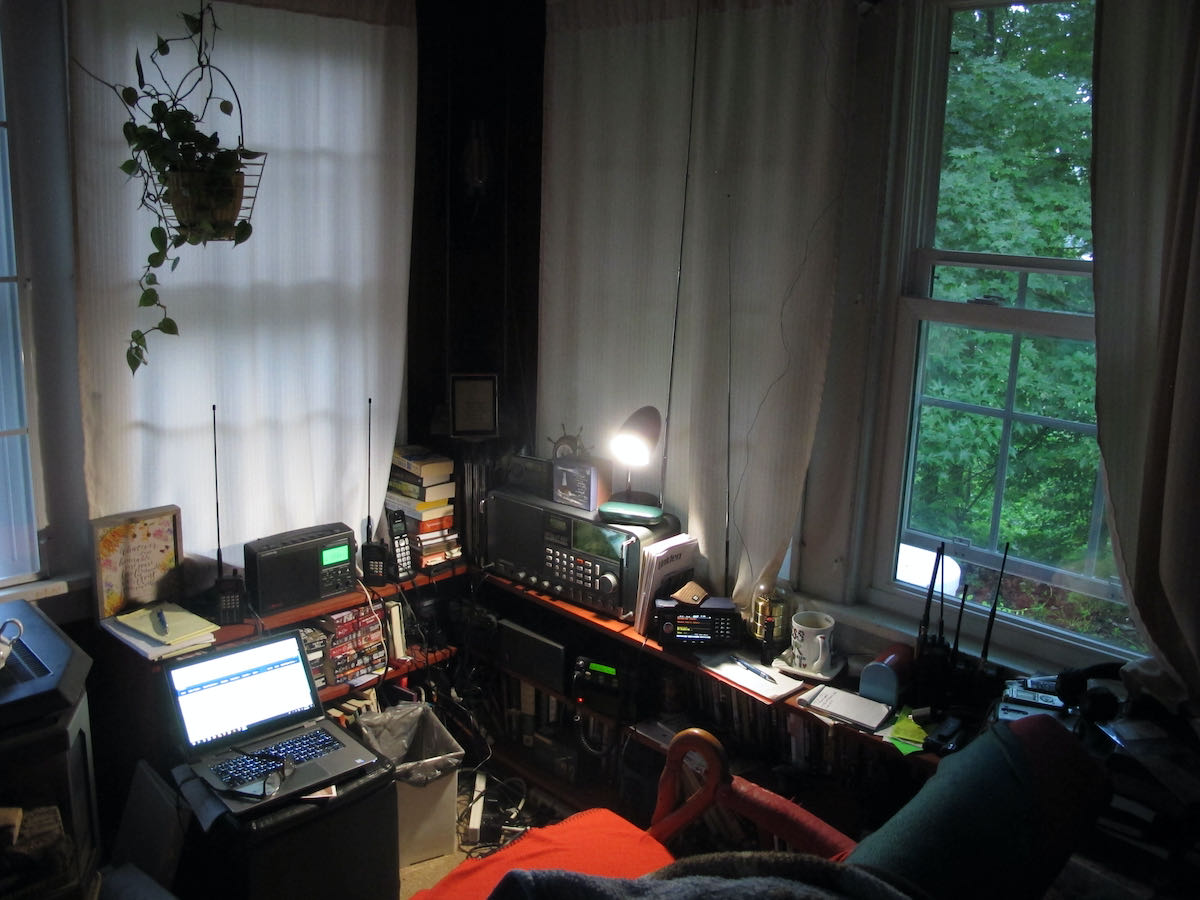
There’s a 50-foot antenna in this room. Can you spot it?

Got reception issues? An idea worth considering: the “Horizontal Room Loop.”

by Jock Elliott (KB2GOM)

When my radio room was in the front of the house (on the east side), it was easy to run a feedline to a large RF-hungry SWL dipole with various stubs and feeders.

Now, however, with my “shack” moved to the SW corner of the house, any attempt to mount an outdoor antenna of any significant length raised potential safety issues because of nearby electrical lines.

Monitoring VHF/UHF is no big deal because of high-performance scanner antennas. HF, however, presents challenges.

My main SWL receiver is a Satellit 800, which has the guts of a Drake R8 and also has a large telescoping vertical antenna. It works okay, but I wanted more signal. I had been looking at small loops and got some great recommendations on Radio Reference, but then I had a thought: what if I turned the 8′ x 12′ room into a giant horizontal passive loop?

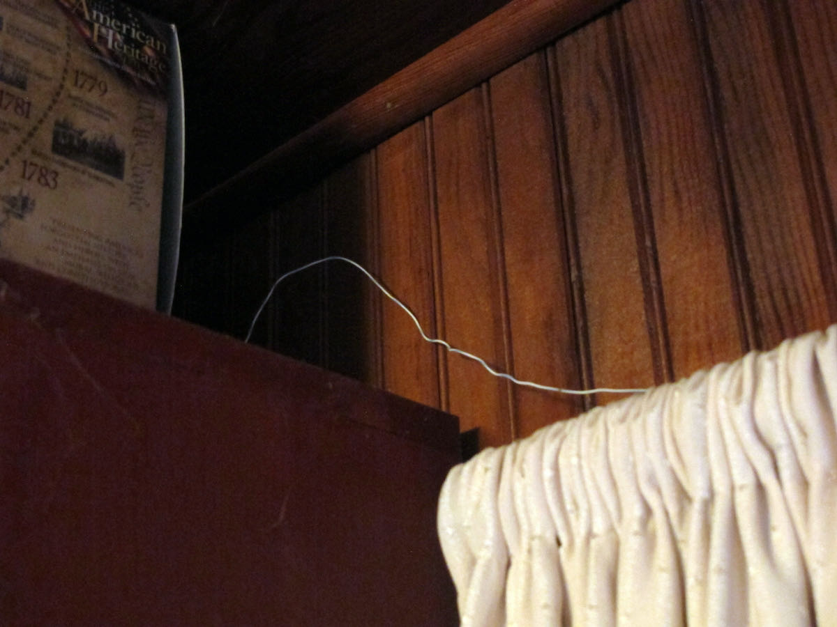
Here’s a hint.

So I called a ham friend and ran the idea by him. “Sure,” he said, “give it a try.” He gave me 25 feet of 4-conductor phone wire. Before I could use it, I had to strip off the outer insulation so I could get at the four separate insulated wires inside. The better half helped. Once I had the four wires, I connected two of them together and ran the resultant 50-foot strand around the perimeter of the room by taping the wire to the top of window frames and hiding the wire on the top shelves of book cases. As a result, the horizontal room loop is near the ceiling, about 7 feet in the air, and the room itself is on the first floor.

With the loop in place, I hooked the ends to the clip-in terminals on the back of the Satellit 800.

There’s a switch on the back of the 800 that allows me to quickly compare the loop with the radio’s built-in vertical antenna. And . . . it works! It pulls in more signal than the vertical (as measured on the signal strength meter), but I have not noticed a dramatic reduction in noise. On some stations, the horizontal room loop brings the signal up to full scale, and then the sound is very agreeable indeed.

In all, I am pleased with the results.

For anyone who wants squeeze more performance out of their shortwave receiver, I can recommend giving the horizontal room loop a try. It’s not expensive; it’s relatively easy to do (and undo if you don’t like the results), and just might improve your shortwave reception.

If you are not blessed with a bunch of window frames on which you could tape the wire for your room loop, you’ll have to get creative, but with lightweight wire, you don’t need a massive support structure. Tape, map tacks, or even self-adhesive Velcro segments might work for putting your room loop in place.

I don’t claim that this is the “ultimate” SWL DX antenna, but it certainly improved my situation. Perhaps others have suggestions for improving it.

— Jock Elliott, KB2GOM

Spread the radio love

How to Build a Simple Linear-Loaded Dipole for Low-Noise Shortwave Radio Listening

Many thanks to SWLing Post contributor and RX antenna guru, Grayhat, for another excellent guest post focusing on compact, low-profile urban antennas:


A linear loaded dipole for the SWL

by Grayhat

What follows is the description of an antenna which may allow to obtain good performances even in limited space, the antenna which I’m about to describe is a “linearl loaded dipole”(LLD) which some call the “cobra” antenna due to the “snaking” of its wires
The arms of the antenna are built using 3-conductors wire (which may be flat or round) and the 3 conductors are connected this way:

That is, connected “in series”, this means that, the electrical length of the antenna will be three times its physical one; this does NOT mean that the antenna will perform like a single wire of the same (total) length, yet it allows to “virtually” make it longer, which in turn gives it good performance even with relatively short sizes. Plus, the distributed inductance/capacitance between the wires not only gives it a number of “sub” resonance points, but also helps keeping the noise down (in my experience below the noise you’d expect from a regular dipole).  At the same time it offers better performances than what one may expect from a “coil loaded” dipole. Plus, building it is easy and cheap and the antenna will fit into even (relatively) limited spaces (a balcony, a small yard and so on…).

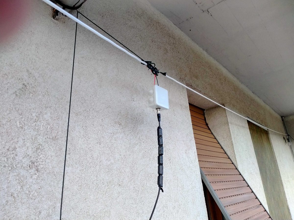
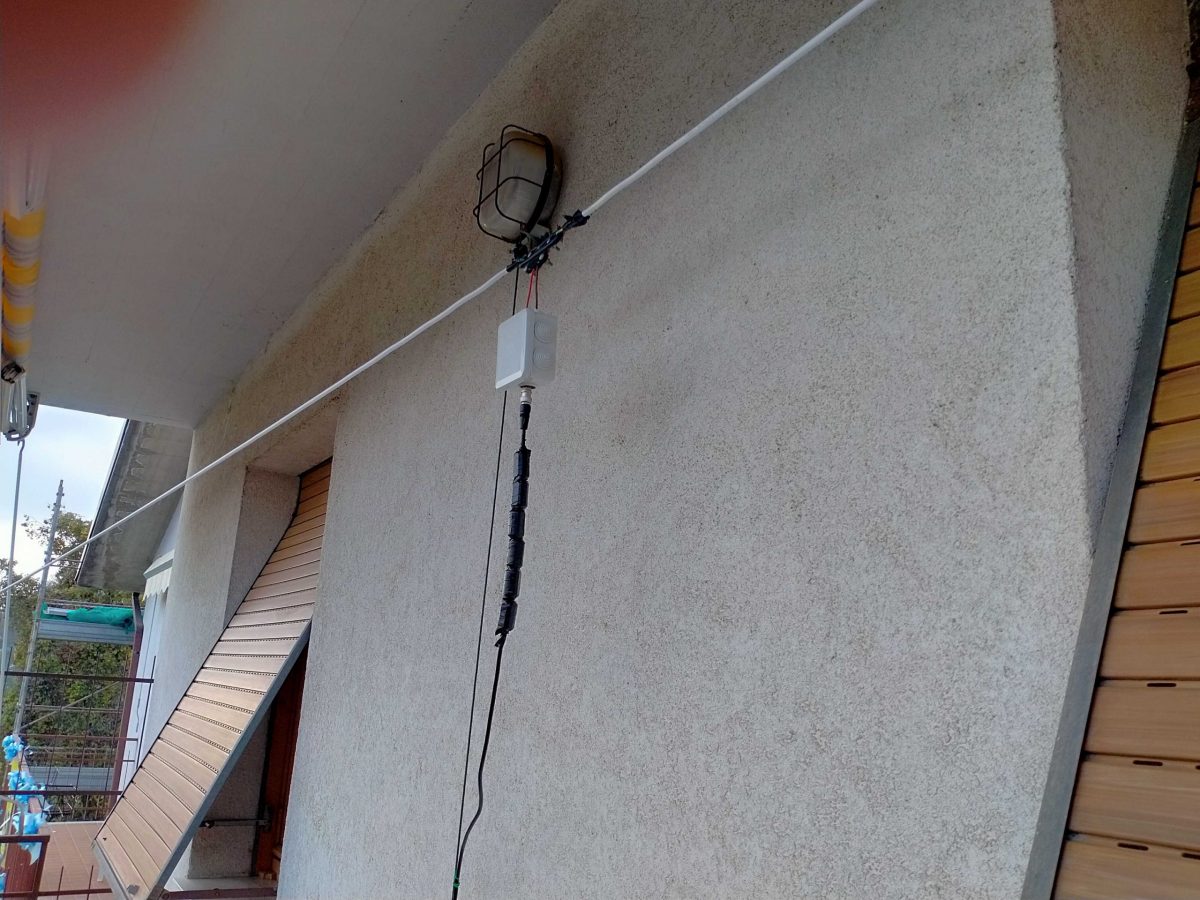
Interested–? If so, read on and let me start by showing my (short – 9mt total) LLD installed on a balcony:

Here it is in all its “glory”–well, not exactly–I fiddled with it lately since I’m considering some mods so the tape isn’t correctly stuck and it has been raised and lowered quite some times, but in any case that’s it.

Bill of Materials

Here’s what you’ll need to build it (the links are just indicative, you may pick different stuff or buy it locally or elsewhere).

  • Some length of 3-conductors electrical wire which will fit your available space (pick it a bit longer to stay on the safe side), it may be flat or round, in my case I used the round type since it was easily available and cheap: https://amzn.to/3g2eZX3
  • A NooElec V2 9:1 BalUn–or, if you prefer you may try winding your own and trying other ratios. I tested some homebuilt 1:1, 1:4 and 1:6 and found that the tiny and cheap NooElec was the best fitting one): https://amzn.to/3fNnvce
  • A small weatherproof box to host the BalUn: https://amzn.to/33vjZy3
  • A center support which may be bought or built. In the latter case, a piece of PCV pipe with some holes to hold the wires should suffice. In my case I picked this one (can’t find it on amazon.com outside of Italy): https://www.amazon.it/gp/product/B07NKCYT5Z
  • A pair of SMA to BNC adapters: https://amzn.to/37krHwj
  • A run of RG-58 coax with BNC connectors: https://amzn.to/2JckHcR

Plus some additional bits and pieces like some rope to hang the antenna, some nylon cable ties, a bit of insulated wire, duct tape and some tools. Notice that the above list can be shortened if you already have some of the needed stuff and this, in turn will lower (the already low) cost of the antenna.

Putting the pieces together

Ok, let’s move on to the build phase. The first thing to do will be measuring your available space to find out how much wire we’ll be able to put on the air; in doing so, consider that (as in my case), the antenna could be mounted in “inverted Vee” configuration which will allow to fit the antenna even in limited space.

In any case, after measuring the available space, let’s subtract at least 1m (50cm at each end) to avoid placing the antenna ends too near to the supports. Also, if in “inverted Vee” config, we’ll need to subtract another 50cm to keep the feedpoint (center/box) away from the central support.

Once we’ve measured, we may start by cutting two equal lengths of 3-conductor wire. Next, we’ll remove a bit of the external sleeve to expose the three conductors and then we’ll remove the insulator from the ends of the three exposed wire (and repeat this at the other end of the cable and for both arms).

The resulting ends of each arm should look somewhat like in the example image below

Now we’ll need to connect the wires in series. We’ll pick one of the cables which will be the two arms of our antenna and, assuming we have the same colors as in the above image, we’ll connect the green and white together at one end and the black and green together at the other end. Repeat the same operation for the second arm and the cables will be ready.

Now, to have a reference, let’s assume that the ends of each arm with the black “free” (not connected) wire will go to the center of our dipole.

Leave the two arms alone for a moment, and let’s install the balun inside the waterproof box. To do so, we’ll start by cutting a (small) hole through the single rubber cap found at one side of the box, then insert the cap reversed, so that it will protrude to the inside of the box and not to the outside. Slide the balun SMA connector through the hole so that it will protrude outside the box.

Now use a marker to mark the balun position and remove the balun from the box. Pick a piece of wood/plastic or other insulating material, cut it to size (refer to marking and to balun size) and drill four holes matching the one found on the balun board. Slide four screws through the holes and lock them with nuts, the screws should be long enough to extrude for some mm. Now insert the balun in the screws using the holes present on the balun board and lock it with nuts (be gentle to avoid damaging the balun). At this point, add some “superglue” to the bottom of the support we just built, slide the balun SMA connector through the rubber cap hole we already practiced, and glue the support to the bottom of the waterproof box.  Wait for the glue to dry.

Just to give you a better idea, see the photo above. That’s a photo of the early assembly of my balun. Later on, I rebuilt it as described above (but took no pics!), the image should help you understanding how it’s seated inside the box–by the way in our case it will be locked by the screws to the plastic support we glued to the box.

While waiting for the glue to dry, we may work on the dipole centerpiece.

If you bought one like I did, connecting the arm “black” (see above) wires should be pretty straightforward. If instead you choose to use a PVC pipe you’ll have to drill some holes to pass and lock the wire so that the strain will be supported by the pipe and not by the wire going to the balun box. In either case, connect a pair of short runs of insulated wire to the end (black) wire coming from each end. Those wires should be long enough to reach the balun wire terminal block inside the box.

Assuming the glue dried, it’s time to complete the feedpoint connection.

Bring the two wires coming from the centerpoint inside the waterproof box. Pick one of the wire terminal blocks which came with the balun (the “L” shaped one should be a good choice) and connect the wires to it. Then, slide the block in place until it locks firmly. After doing so, close the box and screw the SMA-BNC adapter onto the SMA connector coming from the balun. Our centerpiece and arms will now be ready, and will be time to put our antenna up!

I’ll skip the instructions about holding the arm ends and the centerpiece up, since I believe it should be pretty straightforward. Just ensure to put the antenna as high as possible and, if you have room make the arms as long as possible. In my case, due to my (self-imposed) limitations, the antenna was installed on a balcony. The arms have a length of about 3.5m each and the feedpoint (in the image above) sits at about 9m off the ground.

The more acute readers probably noticed those “blobs” on the coax, they are snap-on ferrite chokes I added to the coax (there are more of them at the rx end) to help tame common mode noise. I omitted them from the “BoM” since they may be added later on.

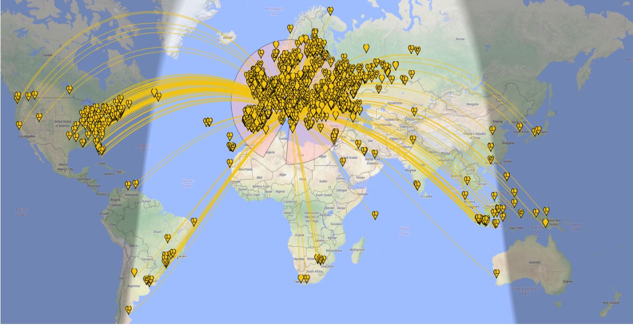
Anyhow, now that you have your LLD up it will be time to give it a test! In my case, I decided to start by running an FT8 session to see what the antenna could pick up during 8 hours, and the result, on the 20 meters band, is shown on the following map (click to enlarge):

Later, that same antenna allowed me to pick up signals from the Neumayer station in Antarctica–not bad, I think!

Some final notes

While running my “balcony experiment”, I built and tested several antennas, including a vanilla “randomwire”, a dipole, and a T2FD.

Compared to those, the LLD offers much less noise and better reception on a wide frequency range. By the way, it won’t perform miracles, but it’s serving me well on the LW band, on most ham bands, and even up to the Aircraft bands–indeed, was able to pick up several conversations between aircraft and ground air traffic control.

All I can suggest is that given a linear-loaded dipole is so simple, quite cheap, and may fit many locations, why don’t you give it a spin–?  🙂

Spread the radio love

Build an SDR station and balcony antenna farm for less than 150 Euros

UPDATE 11 May 2020: We recently learned that the MSI.SDR software defined radio dongle in the following post and tutorial is a clone of the SDRplay RSP1 SDR. We did not realize this when the post was published. Grayhat had done research prior to purchase and believed it not to be a clone, but only using the same chipset as the RSP1 (hence the compatibility with SDRuno). We have confirmed that it is indeed a clone now via SDRplay (clear here to read more via the excellent RTL-SDR blog). What follows isn’t an SDR review. Indeed, Grahat’s post has little to do with the receiver and much, much more to do with building proper antennas! We’ve removed links to the MSI.SDR and would encourage you to invest in the excellent SDRplay RSP1a instead (click here to read our RSP1a review). Thank you for understanding!
Many thanks to SWLing Post contributor, Grayhat, who shares the following guest post. He lives in Italy and has been in lock-down since the beginning of the pandemic. He pitched the idea of building an entire SDR setup from scratch–receiver and antennas–for less than 150 Euros (roughly $163 USD). I thought it was a brilliant idea and I believe he thoroughly enjoyed the challenge of sourcing the components and building a mini antenna farm on his balcony while in quarantine:


From Zero to SDR

by Grayhat

What follows doesn’t pretend to be some kind of “definitive guide” or “last word”, on the contrary, it’s aimed at people who have little or no experience with SDR but want to try putting together a decent station without paying an arm and a leg.

The idea of writing this came to me after reading a number of messages and discussions on various online groups/forums, in a lot of cases, someone bought an SDR (usually the ones coming with a telescopic whip antenna), and after connecting it was expecting it “just to work” or, better said, pretending that the SDR connected to that whip (usually placed on a table right near the computer) could receive ANY POSSIBLE signal, including transmissions coming from the “dark side of the moon.” 🙂 Those folks got scared by the fact that the SDR “didn’t work” and decided to give up; now, this short “guide”  should allow anyone to setup what’s needed to have a working SDR

My self-imposed limitations for this project/experiment were the following:

  1. The whole setup shouldn’t cost more than 150 Euros so that, if after trying the SDR one doesn’t like it, (s)he won’t have paid $$$, otherwise, if (s)he decides to keep it, the resulting station will allow for further expansion/improvement
  2. The available space was considered to be that of an apartment, that is, no large field to put up huge wire antennas or to raise towers, the limit was the one of a balcony (in my home) that is 8 meters (max antenna length) by 3 meters (available height) by 2 meters (balcony width)
  3. The whole setup should be simple and straightforward, no need to solder components or to build special types of antennas
  4. Given the current Covid-19 sheltering, most components should be available online, while for others one may arrange with whatever is locally available (e.g. duct tape)

With the above limitations in mind, I took pencil, paper and rubber eraser (high-tech instruments, indeed) and started writing down a list of the needed stuff, after some writing, wiping and second thought, I came out with the following list, available on Amazon:

Bill of materials

The above includes all the needed stuff to put together a number of wire antennas (random wire, random dipole, loop…) the coax to connect the SDR, a balun to match the coax to the antenna and the accessory parts needed to put up the antenna. The selected SDR isn’t the common “RTL SDR” type, not that they don’t work, but their 8 bit ADC is far from being a good performer, so I decided to pick a different SDR which offers a 12 bits ADC and which also “presents itself” to the system as an SDRplay RSP1.

[Please note: we’ve since learned from SDRplay that the MSI.SDR is indeed a clone of the SDRplay RSP1. Here’s a post from the RTL-SDR blog confirming this. We recommend purchasing the RSP1a as a better alternative.]

Anyhow; all I can say is that after some tests, the MSI.SDR is a quite good unit and offers quite a lot of bangs for the buck, so I believe it may be a good unit for people willing to get their feet wet with SDRs

The above being said, here’s a pic of the MSI.SDR unit with the included stuff:
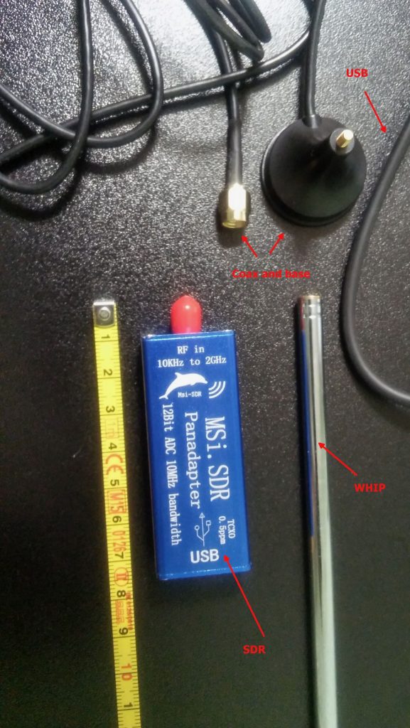
The unit is very small and the box has two connectors, an SMA for the antenna and a micro-USB (like the ones used in cellphones) for the USB cable which is used to both power and control it; the other bits are the telescopic whip antenna (around 98cm fully extended) with a magnetic base and a short run of coax, and the USB cable.

Once I got the SDR I decided to give the included whip antenna a try… well, to be clear, while it will allow you to pick up some strong local FM stations and maybe a bit else, it will only be useful to test if the SDR unit is working (before putting together our antenna), so don’t expect to receive much with that whip, yet… don’t throw it away, it may become useful (more later).

The other important piece is the BalUn. I picked a NooElec “Nine to One” v2, since I’ve used their v1 model and I’ve found it to work well, I decided to pick the newest model which has a better antenna wire connector.  The BalUn, which is in effect a so-called “transformer balun” is really small and the junction box I bought is much bigger, but it isn’t a problem. All in all, the box may host a preamplifier in the future, but for the moment it’s fine for the balun. The following pic shows the balun “installed” inside the junction box:
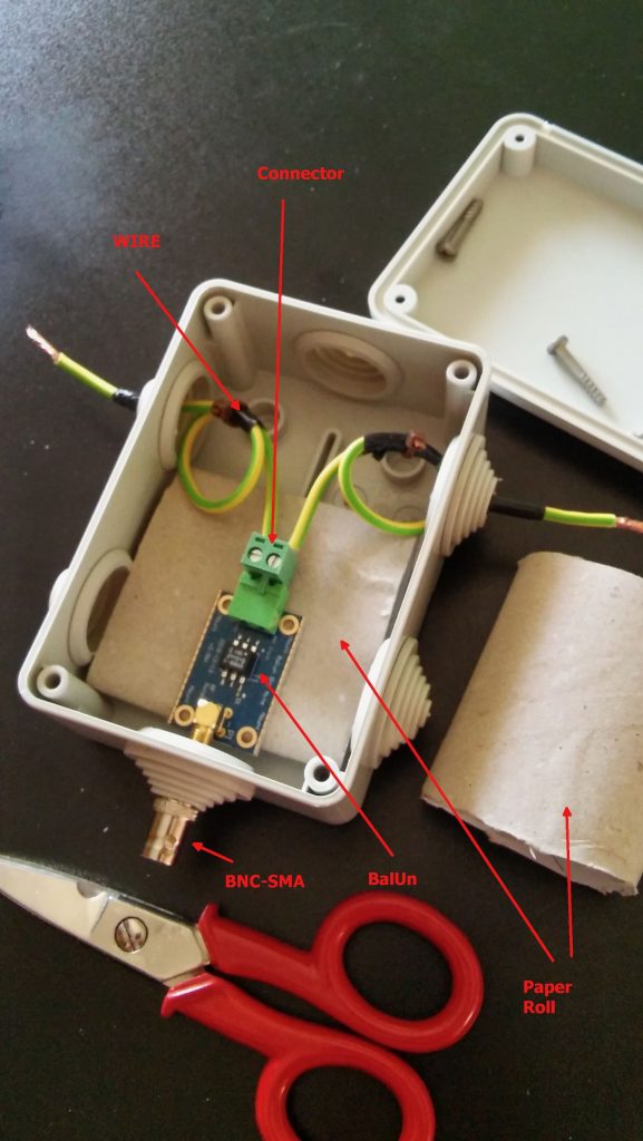
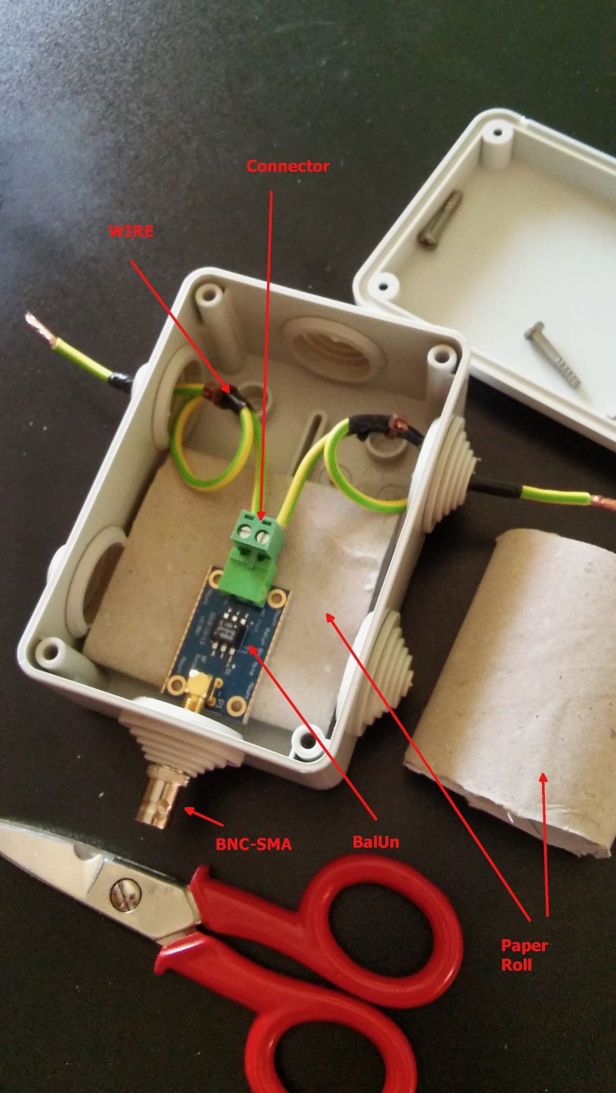
The scissors are there to give you an idea of the sizes; to put together the whole thing, I started by preparing two pieces of wire (the 2.5mm one),  made a turn with each wire and locked them with a nylon cable tier. Those turns will prevent the wire from sliding out and putting a strain on the balun connector.  I did that since I didn’t have plastic washers at hand, otherwise you may just slide two plastic washers (or proper diameter) over the wires and use two nylon tiers to lock them. In either case, the idea is that the “loops” or the washers won’t slide through the box holes and will support that (little bit of) strain caused by the wire connection.

Next, I stripped some of the insulation from the ends and connected the wires to one of the balun connectors (I chose the one in the pic since I believe it’s the most suitable for this setup), at that point I continued cutting the smaller “ring” of the box insulation caps (the two at top and the bottom one). Then I placed a piece of carboard roll (from a kitchen-paper roll) at the bottom to serve as a support (you can see it below the balun). At that point, I slid the balun SMA connector through the bottom hole and used the SMA to BNC adapter to hold it, done so I slid the two wires (connected to the green wire connector) through the side hole and then inserted the connector into the balun. I then placed the other piece of paper roll above the balun and closed the box with its cap. As a note, to properly close it, start by inserting the screw into the cap holes till end, so that they’ll extrude from the bottom, then place the cap over the box and tighten the screws–you may need to use some force to properly tighten it.

Notice that the wire shown in the pic are SHORT, later on I replaced them with longer wires (outside the box) to be able to better connect the balun box to the antenna, but the remainder of the build is the same.

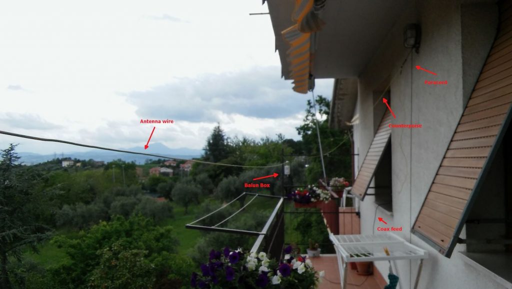
Now that I had my “balun box” ready, I measured the antenna wire and, using the paracord and some nylon tiers, I installed it. I also installed the “counterpoise” wire. For the latter, at first I tried just connecting the remainder of wire to the “gnd” of the balun, leaving the spool laying on the floor, but later on I decided to hang up the counterpoise and the final result was the following:

Click to enlarge

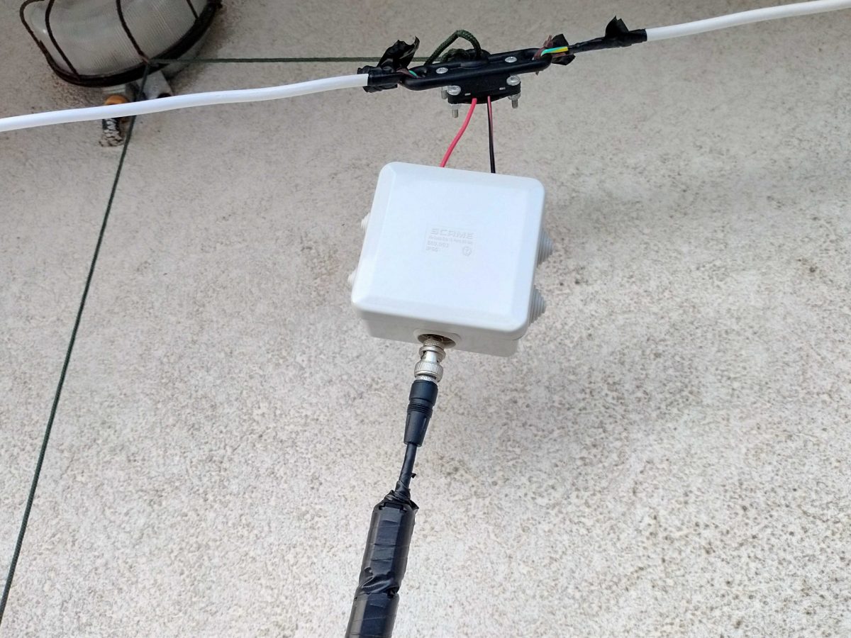
Not a work of art, but then since I was experimenting, I decided not to add PTFE and tape to allow me to quickly rearrange the antenna to run other configurations, yet, the whole setup worked quite well and stood fine to some wind and rain, the picture below shows the balun box with the antenna/counterpoise wires and the coax with the snap-on ferrite chokes.
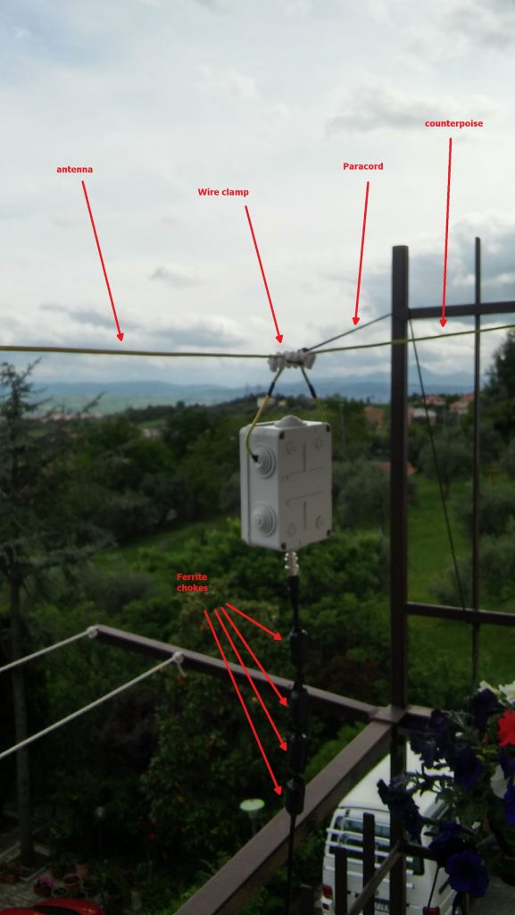
Click to enlarge

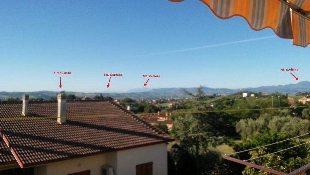
Notice that to avoid putting strain on the balun wires, I used a wire clamp I had in my junkbox–the clamp is then tied to the paracord using a nylon tier and the paracord holds the assembly and keeps the antenna wire in position. The ferrite chokes aren’t properly seated, and I’m planning to remove and re-place them, but for the moment they’re okay. The balcony faces to south/south-west so the antenna has a free horizon of about 270 degrees ranging from the Adriatic coast to the Appennines (Mt. S.Vicino can be seen behind the paracord)–not bad. Here’s another pic showing the horizon to West, just to give you an idea:
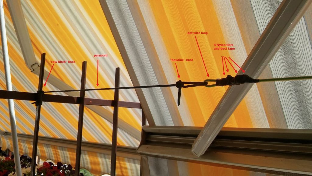
Getting back to the antenna installation, the other end of the antenna wire is tied to the opposite side of the balcony as shown below (let aside the tent/awning, I raise them when using the SDR, also, the bowline knot isn’t correct, I’ll need to tie that again):
The counterpoise instead is supported by a lamp I’ve on the terrace, here’s it’s setup:
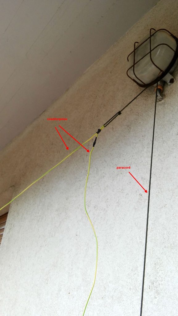
The “paracord” goes down to a plastic bottle filled with a water/chlorine mixture which serves to keep it in place. The remainder of the wire is just hanging down for about 1.5 meters (the counterpoise is shorter than the antenna wire, it’s about 2/3 of its length).

Ok, time to put the antenna and SDR to test, so I brought the coax inside home, connected the other SMA to BNC adapter to the SDR and connected the coax going to the antenna. Note that 15 meters of coax is enough for me, but if one wants a length of up to 25 mt, it won’t be a problem.

I already installed the SDR software, in my case since the unit identifies itself as an “SDR1” I downloaded the SDRPlay “SDRuno” software https://sdrplay.com/windl2.php and since I was at it I also downloaded the PDF manual https://www.sdrplay.com/downloads/ and the “CookBook” http://www.nn4f.com/SDRuno-cookbook.pdf and I heartly recommend reading and digesting them before starting the whole thing (while you wait for all the stuff to be delivered). An important note is that you MUST install the SDRuno software BEFORE connecting the SDR since that way, the SDRuno setup will install the proper drivers and you won’t have issues.

Anyhow, I connected the coax to the SDR and then it was time to fire up the whole thing and give it a spin; so I powered up the laptop (technically, a “transformable” laptop/tablet), started SDRuno, opened the “RX control” and “Main Spectrum” windows and then clicked the “play” button, clicked the “broadcast” band, and the “MW” one and got this:
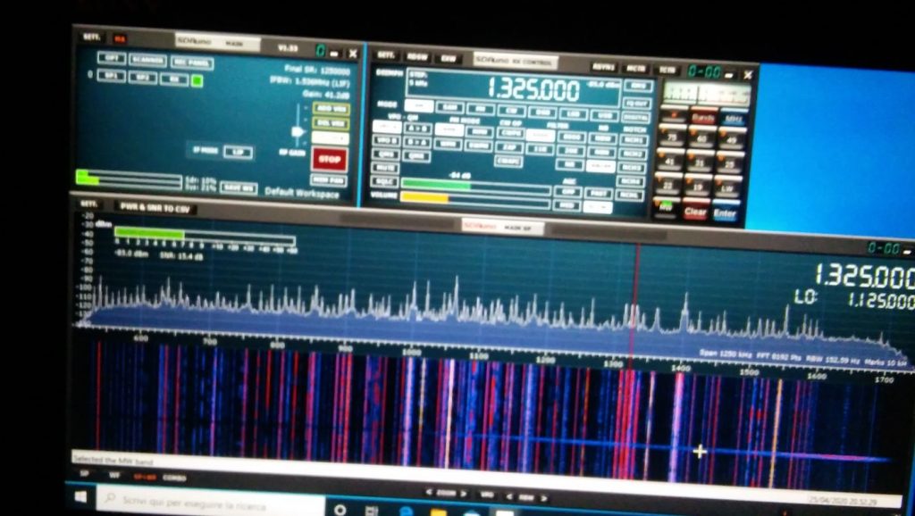
Not exceptional maybe, but not bad, either; in particular if one considers that it’s from a quite short piece of wire which isn’t exactly placed in an ideal position.
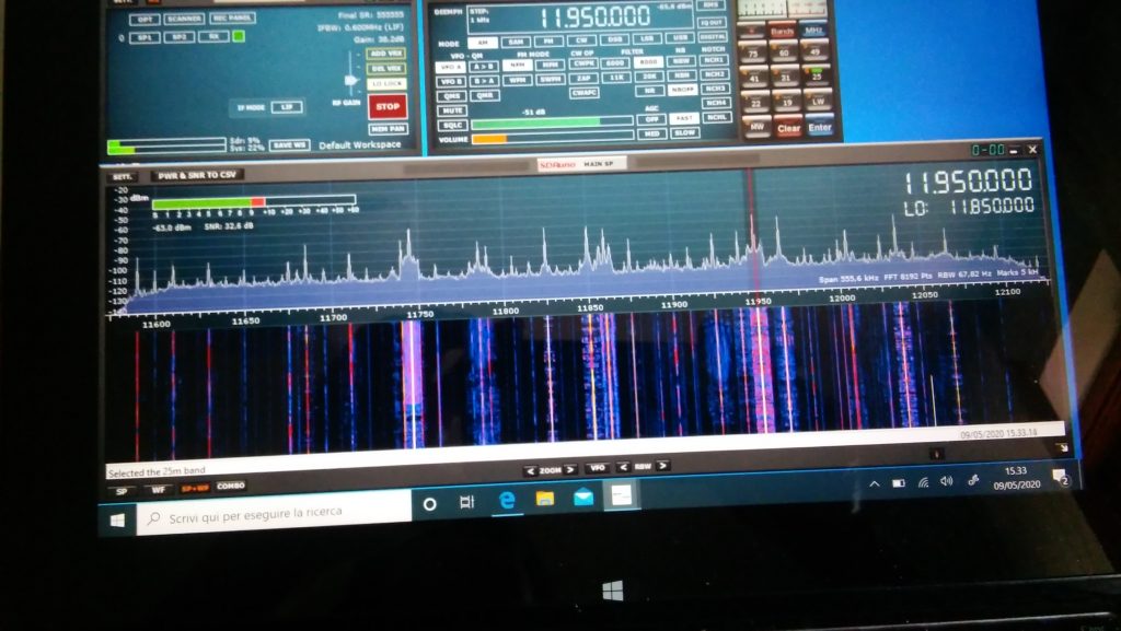
Deutsche Welle

So I went on and explored the bands a bit. On ham bands the SDR picked up signals from the whole mediterranean basin (Cyprus, Lebanon, Spain and then some) and from north too (Russia, Germany, Denmark); then depending on time, I was able to clearly receive broadcasts from China, South America, Africa and more ham QSOs from a lot of places.
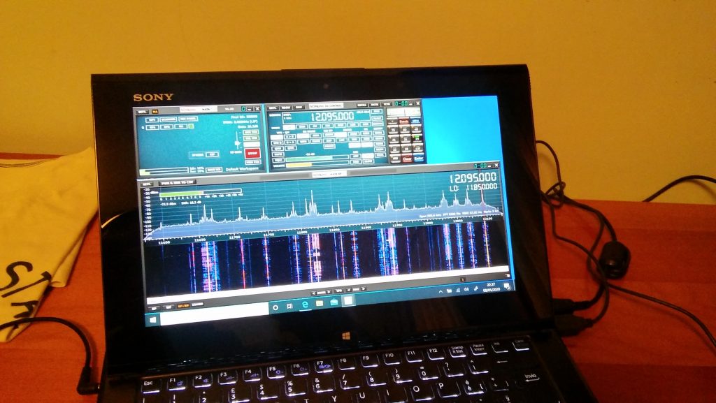
BBC Ascension Island 5/9+ and just a bit of QSB

I must admit I didn’ record the callsigns or stations identifiers (“guilty” your honor–!) but I was more focused on testing the SDR and antenna than running a “DX session” at any rate.  On the BCB bands I picked up WWV, BBC,  VoA, China Radio International, Radio Free Asia, Radio Romania and a bunch of others from Middle East, Asia, Africa and South America. While on the ham bands, I was able to pick up some quite interesting QSOs and then… well, I went hunting for higher frequencies signals!

I got Police, Ambulances, Air control…so even if that “piece of wire” isn’t optimized for VHF/UHF it seems to be working decently there too. By the way, when changing bands you may (and probably will) need to adjust the gain control, but that will be almost the only thing needed to pull in signals

At the end of the day, I can say that I’m quite pleased with the performance offered by this simple and cheap setup. For less than 150 euros you have everything you need, not just the SDR.

Sure, the setup may be improved, but then again you’ll have all of the basic parts, so you won’t need too much. For example, if you live in a really noisy environment, it would be a good idea to use a loop antenna. You would only need a “cross shaped” support (PVC pipes or wood will do). You could quickly put together the SRL (Small Receiving Loop) designed by Matt Roberts (KK5JY) http://www.kk5jy.net/rx-loop/ the balun will be the SAME (yes, no need to wind whatsoever!) so building it will just be a matter of assembling a cross shaped support for the wire (which we already have because it’s the same used for the wire antenna) and you’ll have it. While I already tried the SRL, I didn’t build one to test with this SDR, but I’ll probably do that as soon as SWMBO will start complaining about those “wires on the balcony.”

Also, at the beginning I wrote “more later” when writing about the telescopic whip included with the SDR. Here’s the idea–it requires soldering, so if you don’t want that, skip this: remove the adhesive sheet on the bottom of the antenna base to expose the bottom cap and then remove (extract) the bottom cap. You’ll see a magnetic ring and a “bell shaped” piece of metal (the “ground” for the whip). In the middle of the “bell” there will be the antenna connector which is soldered to the coax wire with a nut holding the connector (and the “bell”) in place. De-solder the coax, unscrew the antenna connector and extract it, at that point you’ll have the telescopic whip and its connector, now you may use them to build the active “whip” antenna described here:

http://www.techlib.com/electronics/antennas.html#Improved%20Active%20Antenna

Notice that it is NOT the “usual” active whip–the circuitry and idea behind it is totally different–yet it works fine and will serve you from VLF (not kidding) up to around 100MHz. It might be a good companion for the SDR. It won’t be as quiet as the loop, yet it may be a valid “all rounder.”

To conclude, I believe that the setup described above is something anyone can afford. You don’t need to be an engineer or to have special knowledge or abilities–it’s just a matter of putting together some bits and pieces.

Obviously, this setup doesn’t require a large space and offers good performance across the bands. Plus it’s so easy to improve since the 12bit SDR is a good starting point

All the best everyone and STAY HOME, STAY SAFE !


Thank you so much, Grayhat!

I love the fact that you invested (however modestly) in a proper antenna setup to better serve you rather than relying on the basic whip antenna that comes with the SDR. You’re right: too often, we invest a receiver, yet invest no money or time into building an appropriate antenna.  The antenna is the most important component in a proper radio setup and those included telescoping whip antennas simply don’t perform well on the HF bands.

Based on our correspondence, I know you had fun piecing together this little system using a simple bill of materials and items you had on hand during the Covid-19 quarantine. Thank you for sharing it here with your SWLing Post community! 

Spread the radio love

Guest Post: More Anti-Noise Ideas

In a previous guest post, SWLing Post contributor TomL, shared his “Evolving, Morphing, SW Listening Station” where he detailed the many ways he’s trying to fight heavy radio interference at his listening post. The following post is TomL’s update:


More Anti-Noise Ideas

(Continuing the hunt for better reception in a foul RFI environment)

by TomL

toml-radios

I have made the following changes:

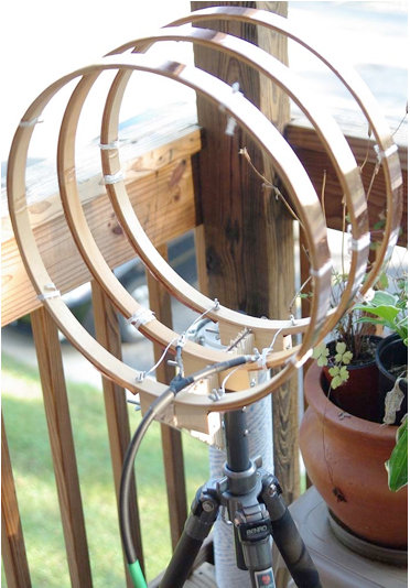
  • Created a prototype mini-loop based on a crossed-parallel idea from VE1ZAC (Jeff).
  • Added a balun from LNR Precision (Parfitt’s EF-SWL) in an experimental configuration.
  • Added to the balun, an outdoor amplifier – Wellbrook ALA-100M.
  • Added a noise canceling unit (MFJ-1026).
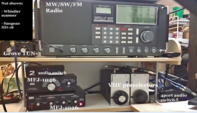
  • Added 2 preselectors, an old Grove TUN-3 connected to the main loop feed and an MFJ-1046 connected to the ground connection of the balun. Both feeds go into the MFJ-1026.
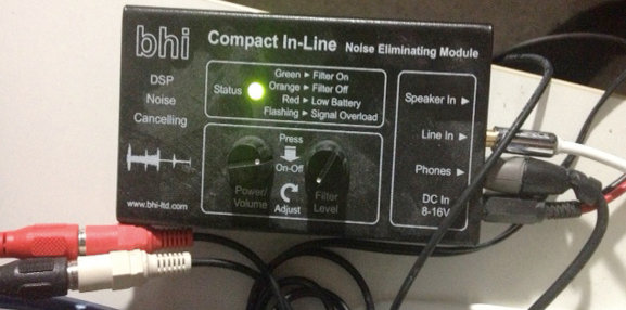
  • Added BHI Compact In-Line DSP filter and two switch boxes to cut it in/out as needed.
  • Added a medium wave noise canceling unit that I have not figured out how to use yet. (Quantum Phaser). The MFJ unit does not work on medium wave without modification.
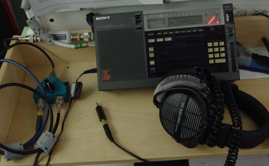
  • Purchased from eBay a used Grundig Satellit 800, a somewhat more robust fixed-station receiver to replace my aging Sony ICF-2010.
  • Other non-related (not shown): Whistler digital scanner + UHF over-the-air TV + FM broadcasts + an AM/FM HD digital radio + high pass filters from MiniCircuits.com – (audio from all these sources is passed to an existing high fidelity stereo power amp and NHT Super One speakers on the computer desk for near-field monitoring). Associated antennas are also hidden on the outside deck (shhhhh!).
  • Large charge card balance!!

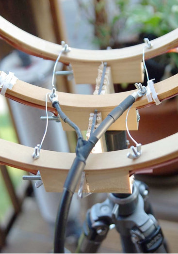
So, here are some pics for the crossed-parallel loop. VE1ZAC web site has all the references if you want to explore further or google him. Mine is purely a prototype and not finished. And should eventually be placed on a rotor (but how to keep my Nazi-like condo association from finding out?!?!?!?).

loops

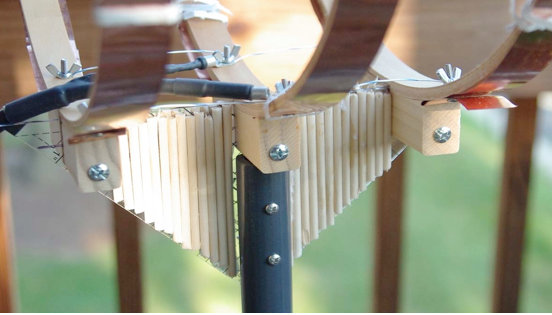
It is three 14 inch quilters hoops from Joann Stores plus some 1-inch copper strips cut from a small 2 meter roll of thin copper from eBay. Then, it is wired in parallel with silver-plated aviation wire on each side with a feed in the middle. Not an optimal placement of the feed, (should go straight down along the pipe). Will fix things up whenever I get some more time.

loops-closeup

loops-closeup2
Seems to be an efficient way to prototype small loops. It is now mounted on a short ¾” inside diameter PVC pipe into a cheap plastic sand-filled deck-umbrella stand. Loops are light and somewhat flimsy, so I mounted the three loops on a plastic triangle ruler and dowel sticks glued to the sides for some extra strength. Good enough for now.

The EF-SWL balun is also in an experimental configuration. Since I read somewhere that loop antennas have a very low impedance at the feed point (like, 10 ohms or lower), I thought I might try a balun that is meant to lower the impedance and mount it backwards. I don’t have a picture of it but the SO-239 output is facing the loop and the screw terminals are facing the direction of the radio. My feeble brain thinks since it is a passive device of coils on ferrite, it should work bidirectionally for receive only applications like this. It seems to work but I have the excuse that I really don’t know what I am doing! 🙂

bhi

BHI unit in action.

The BHI DSP filter is useful in some circumstances but I find it fatiguing to listen to. The audio from the Sattelit 800 is so nice, I mostly like it without the DSP. The DSP narrows the bandwidth significantly, somewhere around 4 kHz or less from my hearing. I like that the Grundig has two tone controls. And it also has a stable SSB and on very strong signals with clear audio, I like to listen with SSB lower or upper sideband. But the DSP is useful at times for hash-like noisy signals; it is not quite as good on buzzing noise and I wish the Satellit 800 had a noise blanker, but that would have been a more costly purchase, like a Drake R8A.

So, in a nutshell, I have a discovery about noise here: it is all around me and ubiquitous, like the air I breathe!

I find it hard to null and also worry about peaking a station signal at the same time. However, I do have a lower noise floor with the experimental loop sitting outdoors, especially on medium wave (the Wellbrook amp + loop works great on the lower frequencies – am able to get eight different medium wave stations carrying Major League Baseball games at night – it would be nine to get WFAN for the New York Mets but the local Chicago Cubs station covers the adjacent frequency with horrible digital hash! ***Bleeping*** digital junk!).

Also, the signal level is noticeably lower using the loop. Then, add in the effect of the MFJ Noise Canceling unit, the usable signal gets even weaker.

The bottom line is, I can now finally enjoy listening to many SW broadcasts, BUT only the strongest signals. Anything else is still hopelessly lost in the noise. So, gains are limited.

On the other hand, and something else I learned by doing is that, any 1 or 2 dB signal/noise ratio improvement will help with the final audio output in the end product. Using low-noise amps, loops, noise canceler, preselectors, grounded connections, ground isolators at the input of every receiver, high quality stereo amplifier and speakers, tone controls, SSB vs. AM Sync, weird antenna configurations, etc, etc. It all helps in the end to some degree.

Tinkering is an art that involves a lot of thinking/doing iterations! And high quality parts must be used all along the chain or it could degrade the signal.

Below are some audio samples, not very well recorded, but can give some idea of the incremental improvement with each enhancement (turn up the volume). NOTE: other people may get better or worse results depending upon individual situations, type of antennas used, etc, etc.

Recording 1: R. Marti. First 10 seconds an indoor antenna with no noise reduction, second 10 seconds the outdoor loop without the MFJ-1026, the third 10 seconds with the MFJ-1026, then switched off and on to hear the difference.

Recording 2: R. Marti. MFJ -1026 is ON. Last 15 seconds is SSB, very thin sounding. Really only good for strongest signals. I liked the AM Sync better (Satellit 800 is really a Drake SW8 in disguise with a quality AM Sync). But, SSB can sound excellent with very clear voices with a steady and strong signal (The Satellit 800 does NOT have IF-shift or a BFO to fine tune an SSB reception, so the station must be exactly transmitting on the kHz mark, which most are nowadays).

Recording 3: R. Marti. MFJ-1026 is ON. Last 20 seconds you hear me switch in the two audio switches and the BHI DSP is on its lowest setting. Narrower and clearer with some reduction of background noise. I find I only like going up to about 4 on the DSP dial, after that the audio fidelity starts getting more choppy with digital artifacts that sound like dripping water. I tend to like higher fidelity. One nice thing about the BHI DSP is a faux-stereo that helps a little with voice intelligibility by helping the brain naturally filter the noise. Faux-stereo is ON even when the noise reduction circuit is manually turned off (power must be on and bandwidth still sounds narrowed).

Recording 4: R. Nacional Brazilia. First without MFJ-1026, then ON, then OFF, then ON, then with the BHI kicked for the last 20 seconds.

Recording 5: Greece. Switching the MFJ-1026 on and off every 5 seconds. In this particular case, the signal was weak and fading a lot. The MFJ OFF was also weaker than with it turned ON. That is interesting behavior, usually it is opposite. It pays to play with the settings a little. At other times, and less frequently, the MFJ unit turned OFF sometimes sounds better than with it ON and tuned for less noise. Go figure!

After all the tweaking is done, and I cannot get any more performance out of this, I will probably have to move to a nice, quiet neighborhood and setup a nice antenna farm!!

In the meantime, I do enjoy listening to the stronger stations from North America, Cuba, Brazil, Europe, and Australia with less noise than before.

73’s

TomL from NOIZEY Illinoiz


Once again, Tom, thanks for sharing your RFI elimination journey!

I love how you take on this noisy problem by experimenting and seeing it more as a challenge than an obstacle to enjoying your hobby.  Great job! 

Spread the radio love

Guest Post: My Evolving, Morphing, SW Listening Station

Many thanks to SWLing Post contributor, TomL, for the following guest post:


Sony-2010

My Evolving, Morphing, SW Listening Station

by TomL, May 26, 2016

My interest in radio listening has been rekindled after a long hiatus in parallel to my dwindling interest in Mainstream Media.  It is now about 8 years without cable TV and I seriously do not miss it, especially with the evolving nature of discovery with respect to other forms of media.  SWL radio was important to me in my formative years during the Cold War; fascinating were the many ways governments used shortwave radio to influence populations, each with their own brand of propaganda!  Young people today know nothing about the endless (and entertaining) tirades of East German editorial commentaries denouncing the evil, decadent West.  Or, of the free, large-sized envelopes full of travel and promotional brochures, pennants, bumper stickers, and booklets sent from the government broadcasters such as Poland, Hungary (yes, communist countries!), Australia, Netherlands, etc. just for sending in one simple QSL report!!!

I quickly realized that those days are gone forever, consigned to a period of history where radio was THE main method of disseminating copious amounts of government propaganda to very large swaths of humanity.  Now, the internet and cable TV fulfill that function in a much more CONTROLLED manner, both technically and socially (Big Brother like).  So, I have diversified my interests and have an unusual listening station.  It is multiple things in one small space.  You see, I live in a very small condo in a noise-plagued environment with only a 2nd floor wooden deck (owned by the Condo Association!) in which to put up any outside antennas.  Only a single “Dish” type antenna is allowed.  So my shortwave antenna needs to be well hidden.  Same for the TV antenna, since I also have a north-facing deck, I cannot have any line-of-sight to the Southern sky for a Dish.

The first wire antenna strung from the top and brought inside was a dismal failure receiving nothing but noise.  I gave up for a couple of years.  I built a loop TV antenna and mounted an FM antenna instead since those were less susceptible to noise issues.  Also recently added to this station are two cheap 4G antennas with wires into a single Verizon USB aircard plugged into my computer and getting up to 14 mbps performance.

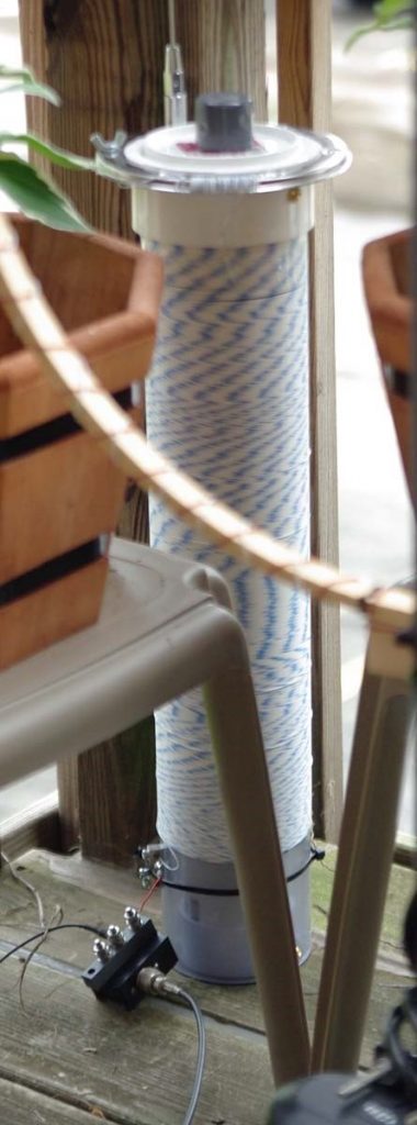
But, I still wanted to try shortwave radio again (and medium wave too) but the noise issues were very, very discouraging.  S9 noise on some bands.  Tried preselector, a noise “phaser”, different lengths.  Nothing worked.  However, I read something from an amateur radio operator in Northern California who had a space problem.  He put up a helically-wound-vertical (HWV) antenna with radials for 160 meters (John Miller HWV antenna).  I also read about various “broomstick” antennas.  So, I tried my own version with an old RF Systems Magnetic Longwire Balun I still owned and NO radials.  Put it together with a 2 foot long, 4 inch schedule 40 PVC pipe wrapped in 200 feet of 18 awg magnet wire.  Well, still noisy but, at least now I had a portable antenna!

So, I went camping in March of this year!  Holy Cow, was it cold out but the helical antenna performed well enough to hear All India Radio for my very first time, a small 1kw Mexican station in the 49 meter band, and various others from Asia that were elusive for me in the distant past.  I was finally encouraged again to continue my research.  I did this a few more times and finally got tired of going camping just to listen to a radio!  NOISE at home was still the big bugaboo to kill (and it still is).

I read up on Common-mode noise travelling on ground and shield components of antenna systems.  So I bought a bunch of toroid ferrites of different types to cover different frequencies (something about initial permeability….) to make my own homemade “Super RF Choke” to cover all frequencies made on a Home Depot Homer bucket lid, winding the coax 5 or 6 times through all the toroids, the full diameter of the lid.

Measurements by Jim Brown published on the web (RFI-Ham.pdf), pages 32-33) indicate good choke performance using coax with these larger-sized coils.  I still hoped to salvage the use of the HWV antenna.  So, added the choke and noticed some improvement across most bands (less noise).  Medium wave broadcast was not effective and decided that I did not want to keep tuning an antenna that HAD to sit outside to get away from the noise inside my listening station.

I also shut off the power to my condo and found out which noise sources were mine vs. other noise that came from all the neighbors (very important step to do!!!).  For instance, I did not know before that USB charging adapters are PURE RF-NOISE EVIL in an innocently small package?!?!?!  I rearranged wiring to shut off certain devices and power strips when I want to listen to the radio!

So, I kept reading.  Found out about another magnetic balun from Palomar.  Tried it but not impressed –  performance was too lossy compared to the good old RF Systems MLB (what a great product that was back then!).  Kept reading and found out good things about the EF-SWL from PAR electronics (product is now made and sold by LNR).  The ground connections on it (and the Palomar) intrigued me.  So, I decided to go to Hamvention for the first time, even though I was skeptical of finding anything useful, I told myself, I could at least buy the EF-SWL on sale (which I did).

Installed EF-SWL to the HWV but no difference compared to the RF MLB. The antenna did perform better outside on the deck in the far corner, so there it still sits.  Then, I hooked up the wire they gave me with the EF-SWL to the ground and it resulted in MORE noise.  Then, took off the jumper (which connects the coax shield to the ground side of the balun) and connected only the middle post (balun ground) to the ground wire and a lot LESS noise resulted along with a small reduction in radio signal level!!!  Finally some progress – the wire seems to be acting like an old-fashioned “counterpoise”, which is misunderstood these days.  Apparently, back in the 1930’s-1950’s, people involved in radio knew the differences between an “earth ground”, a “radial system”, and a “counterpoise”.  Technically, they are all different and their use is different as a result.  Now, people moosh all these concepts together interchangeably which risks creating very ineffective antennas.

Photo of installed EF-SWL at the bottom of the HWV with coax at the output, the red magnet wire input on top, the middle post for the counterpoise wire, and the coax shield post is unused. 

Photo of installed EF-SWL at the bottom of the HWV with coax at the output, the red magnet wire input on top, the middle post for the counterpoise wire, and the coax shield post is unused.

The HWV antenna now has 600 feet of 26 awg teflon wire on the outside PVC, an inside 3 inch PVC “sleeve” with 102 Russian ferrite rods, a 56 inch stainless steel whip at the top, and one inch hole through the center to accommodate the 7 foot PVC mount to my carbon fiber photo tripod when I take it camping again.

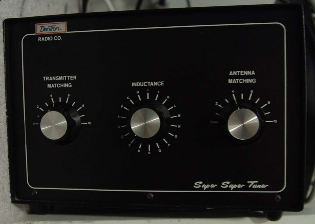
So, I am on a new quest to understand counterpoises, how to actually TUNE them and, hopefully, how to use them to increase the performance of shortened antennas like my HWV (something about reducing the dB loss incurred by shortening….).  A second result I hope will be how to use the counterpoise to keep signal-to-noise ratio high at the same time (maybe with this used $100 Dentron Super Tuner bought at Hamvention?).

Transmatch

Also bought at Hamvention (thanks Thomas W. for the tip!!) and installed Bonito’s Galvanic Antenna Isolator GI300.

If input directly to the input of the radio, led to more reduction in noise and signal!!  Too much actually, so I took off my Super RF Choke and now I had a better result compared to the EF-SWL with the RF Choke (slightly cleaner sound with less hissy noise).  Apparently, the GI300 completely isolates the coax shield, better than my homemade choke!  The requirement is to use coax from the feedpoint and not bare wire.  I then placed a few clamp-on ferrites I bought from eBay to help with slightly higher frequency choking of the shield at various places on the feedline.

Bonito-Galvanic-Isolator

Photo of GI300 on radio with NO extra coax lead into the radio at right (Thanks to Dennis Walter of Bonito for that tip)

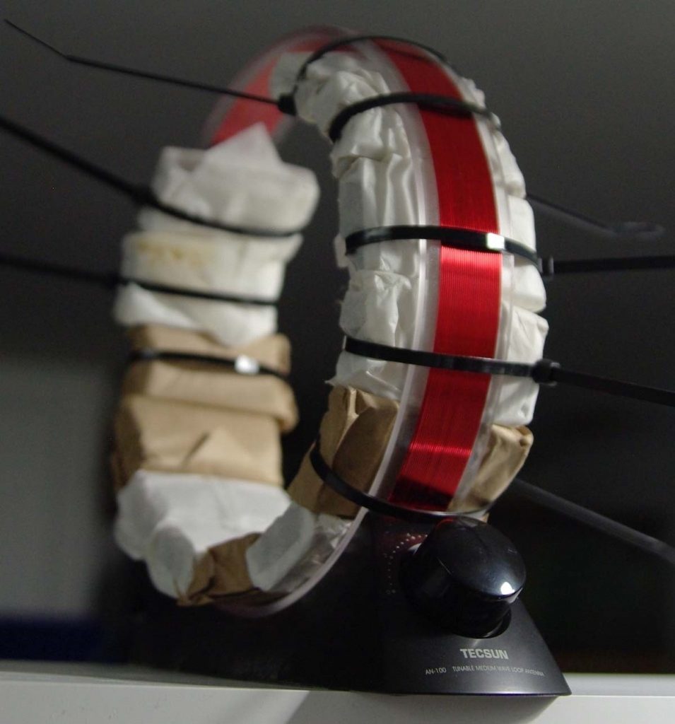
Before Hamvention, I wanted to try out AM broadcast.  I wanted to know more about this “FSL” antenna a well-known eccentric from Ireland (Graham Maynard FSL) developed before he passed away a few years later.  So read up and bought a whole bunch of ferrite rods and tried different configurations.  Well, my particular design did not work all that well because I did not follow directions for winding wire into a balanced design.  So, I added all those ferrite rods to the 2 foot HWV (inside a 3 inch thin-walled sewer PVC pipe).  The antenna is louder down to about 3 MHz with a stronger signal (including noise) than without.  I do not have measurements, and find it too time consuming to document.  Maybe one day, I will compare and document by sliding the ferrites out on the 3 inch PVC and measure actual signal levels.  The ferrite sleeve seemed to pick up MORE noise and radio signal than without it.  So, if you need more signal strength in a small package below 7 MHz, then the idea seems to have merit.  But since it increased noise as much as radio signals, it has limited usefulness to me.  I do have another project where I will put ferrite bars onto a tuned medium wave loop antenna (Tecsun AN100) that is much more portable and directional.  The bars and loop were both relatively inexpensive from eBay.  The ferrites change the tuning lower, so I have to figure out how to make it tune higher again…….

Photo of unfinished MW loop project.

Photo of unfinished MW loop project.

Summary

Evolving understanding of dealing with major problems like overwhelming noise and limited space have led to unexpected additions to my SW Listening Station:

  • A 2 foot long, 4 inch diameter helically-wound-vertical antenna (HWV) with way too much wire on it (and now inserted with 102 160mm Russian ferrite rods on a 3 inch diameter “sleeve”). Originally built because of its portability.  Can now be mounted on a carbon fiber photo tripod with a 7 foot 3/4” PVC pipe through the center length
  • A magnetic balun from LNR (designed by Parfitt) attached at the feedpoint of the antenna
  • A proprietary galvanic isolator from Bonito attached right at the radio’s antenna terminal
  • A “boat anchor” Dentron Super Tuner attached to the HWV feedline to help tune it
  • An unfinished MW loop antenna with more ferrite bars
  • An unused, homemade toroidal Super RF Choke
  • Clamp-on ferrites everywhere in proximity on wires and power leads
  • Re-arranged power strips and wires as needed for easier shutoff in functional groups

For shortwave, I still pick up mostly noise on many bands.  With the uncalibrated S-meter on the ICF-2010 – 49 meters is around S1 (before about S3).  31 meters is MUCH improved and is now listenable to stronger stations (S2 instead of S7 noise!).  Even 19 and 16 meters is improved from S6 to S7 down to about S3 now – noise still too annoyingly loud to understand any language being spoken however.  And forget about DXing from this location!  Will have to go camping again soon.

BUT, listening now to Voice of Greece, Radio Nacional Brasilia, or Radio Romania International is a much cleaner sounding experience than just a couple of months ago.  They are there to re-discover and appreciate, even though many speak a foreign language and I do not understand a word they are saying!  Also, there is the odd observation (like just this morning), that I can actually learn to enjoy listening to Country Music if it is the unique sounding Australian flavor!!

Do I miss cable TV??  Not a bit!!

Future investigations

  • Employ the Dentron Super Tuner in various configurations to find any improvements (currently attached to the coax of main feedline from the EF-SWL, it is helping tune different SW bands (not sure why it helps, does not make sense, must be a mismatch between coax and balun)
  • Obtain old book(s) on counterpoises
  • Get a Linear DC power supply for use with all the EVIL RF-spewing devices that use 5 volts. Maybe this one:  (Tekpower 3Amp Linear)
  • Replace any cheap/old RG58 cables with LMR-240 or similar
  • Finish the AM loop w/ferrites so I can take it places
  • Perhaps an ultra low-noise outdoor amplifier for the HWV, depends on counterpoise experiments: (Wellbrook ALA100M-2)  (I don’t want to spend that much money now)
  • Somehow use a noise antenna with a better phaser: (DX Engineering NCC-1) (gulp, don’t want to spend THAT much money now also!!!)
  • Get some relief from background noise using a really robust noise blanker. I don’t want to spend on the portable radio, would rather get something like the Bonito 1102S or an ELAD model both supposed to have excellent audio quality and excellent DSP noise blankers.  But that means getting a cheap laptop to run it and replacing the Sony.  MOAR big bucks…. but not right now
  • Maybe a real loop antenna, BUT it has to be remotely tunable and remotely turnable and small enough to HIDE. MOAR big bucks, sigh….

TomL from noisy Illinois, USA


Many thanks for sharing your experiences, Tom! Also, it was great meeting you at the Hamvention this year.

I must say that there is something to be said for brute-force experimentation when it comes to mitigating radio interference. I hope you keep us posted as you continue to experiment and improve upon your unique listening system.

Spread the radio love

Have you ever installed a covert shortwave radio antenna?

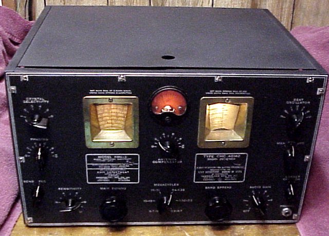
The Hammarlund RBG CHC-46140 (Photo by Rich Post, KB8TAD)

The Hammarlund RBG CHC-46140 (Photo by Rich Post, KB8TAD)

Yesterday, in a comment thread, SWLing Post reader Dan described a covert antenna he once installed in a student apartment:

I’m waxing nostalgic now, but I had a great set-up for a couple of years back in the ’70s. The receiver was a black WW2 Navy surplus Hammarlund RBG CHC-46140. (I still have it).

I was a student living in an apartment on top of a two story, wood-framed apartment building. The attic access for that building was from the ceiling of the wardrobe closet.

During a Christmas break I was probably the only occupant of the building. I snuck into the attic and installed a set of five switchable dipoles. I had a good 60′ of space to work with and the antennas were broadside to the southwest. This was quite a memorable listening post.

When I moved out, I cut the coax to the dipoles and used toothpaste and borrowed pieces of “cottage cheese” to fill the five holes in the ceiling. Those antennas are probably still there.

Indeed, I bet they are still there, Dan!

In reply to Dan’s comment, Walt Salmaniw, noted:

Dan, reminds me when I was stationed in Germany in the early 80’s.

We lived in old French officer’s quarters. Basically, 4 story buildings with the upper floor/attic uninhabited.

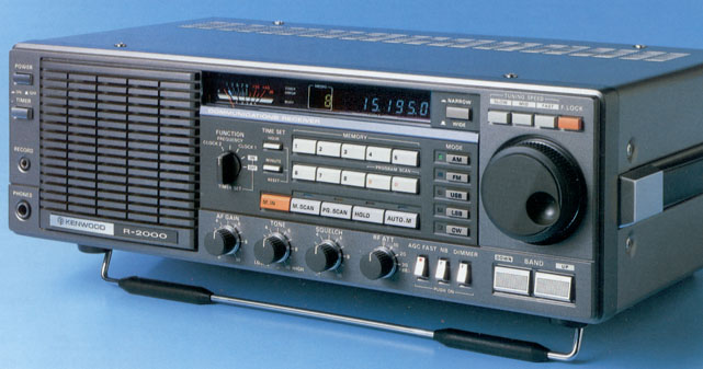
The Kenwood R-2000 (Photo: Universal Radio)

The Kenwood R-2000 (Photo: Universal Radio)

I put up some nice 60 m dipoles in that space, with a goal of hearing a lot of tropical band DX, which I did using my Kenwood R2000 receiver.

Those were the glory days of dxing!

Thanks, Dan and Walter, for sharing those stories. The thread reminds me of a post we published sometime back where one young listener installed a wire antenna in his home while his parents were away. (I can’t seem to locate that post at the moment for a link!).

Though not nearly as elaborate as Dan and Walter’s antennas, I did install a small covert antenna once myself.

In the early 90s, I lived in Grenoble, France, in a four bedroom house in which three bedrooms were occupied by university students. The landlord was a rather fussy elderly woman who lived on the ground floor. I never dared ask her if I could string a random wire outside my top floor bedroom window. Though she was mostly fair and even sweet at times, I knew what the response would be if I asked for permission: a firm “Non.”

One night, I opened the bedroom window and carefully connected a short wire antenna to a nail on the side of the house, above and slightly to the side of the window. I had to stand on the window and hang out of the house to do it.

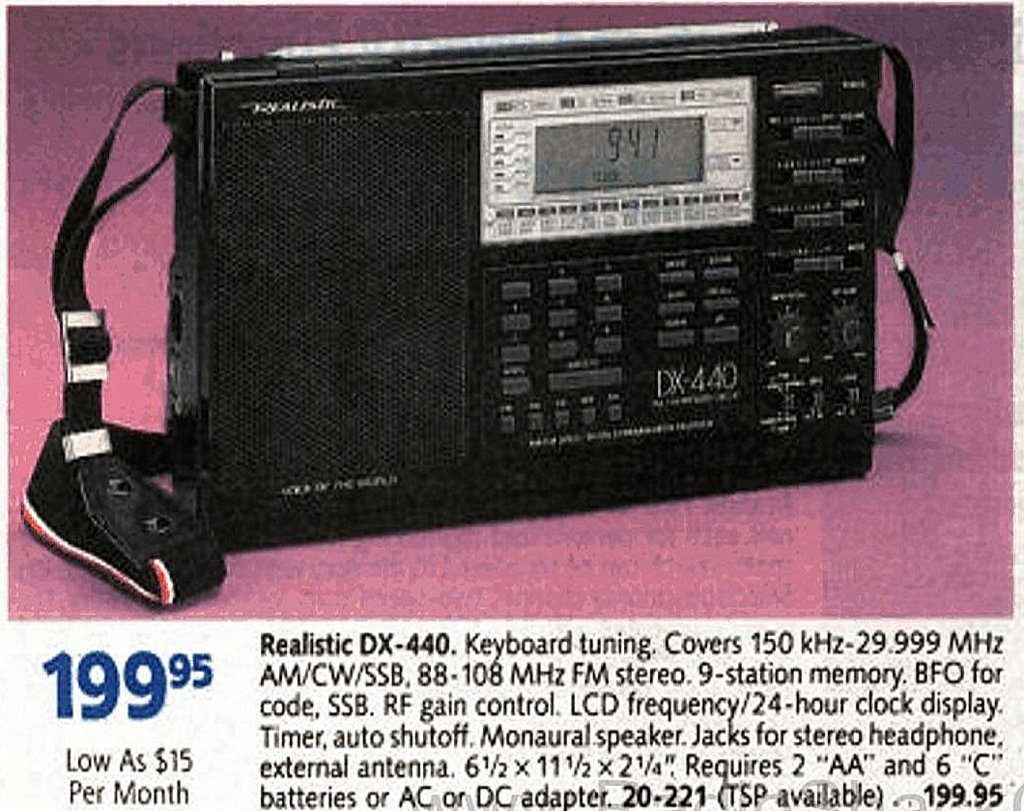
The Realistic DX-440

The Realistic DX-440

The antenna dangled there the whole year I lived in that room and served me quite well. I’d simply open the window and clip it to my Realistic DX-440. I did remove the antenna before before I moved back to the States, but it was virtually undetectable against the  exterior wall of the house.

Other covert antenna installations?

Please comment if you’ve ever installed a hidden antenna as well. (I love this stuff!) Besides…who knows…your antenna might benefit someone in need of a hidden antenna today!

Spread the radio love

Ken’s low-profile, low-cost vertical antenna

Vertical1

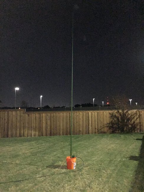
Ken’s antenna “deployed” in his back yard.

SWLing Post reader, Ken Hansen (N2VIP), writes:

A few months ago I purchased a couple S9V18 18′ vertical antennas for $65 at cheapham.com, with the intention of deploying a quick HF aerial at my HOA-laden home for ham radio use. I found they work great for SWL.

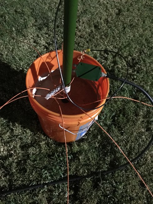
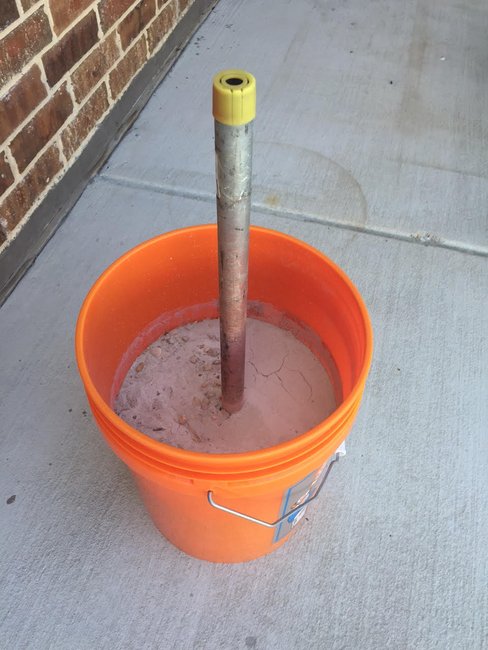
The S9V18 antenna is made to slip over a 1″ o.d. pipe driven into the ground at least a foot, with 12″ of the pipe rising off the ground. You can pound a two foot pipe half-way into the ground, or do as I did and fill a bucket with cement and stick the pipe in that half-way.

This is a 'close-up' of the bucket. Note the plate the ground radials are attached to, it's from Home Depot, it's a bus bar designed to bond the ground wire for each circuit in a breaker box.

This is a ‘close-up’ of the bucket. Note the plate the ground radials are attached to–it’s from Home Depot, it’s a bus bar designed to bond the ground wire for each circuit in a breaker box.

After adding a reasonable ground plane of 8x 14 ga wire cut about 15′ long I hooked up a 4:1 balun and ran it to my Kenwood TS-570D.

What I found was the aerial not only worked well on 20 meters, it also made a great shortwave aerial! Stations were booming in here in Texas at night.

Vertical4

The antenna slides over the pipe sticking out of the concrete in the bucket. Here is a picture of the bucket before the antenna base is slipped over it.

My ‘discovery’ was that a nice, modest vertical antenna can really improve reception on SW bands…

Cheapham.com sells the S9V18 antenna on close out for $35/each, the 2′ pipe is a few dollars more, add in a bit of coax and a modest ground plane and you can really up your SWL ‘game’.

Antenna on closeout:

http://www.cheapham.com/s9-v18-18-vertical-antenna-closeout/

I suggest anyone buying this antenna seriously consider buying additional clamps at the same time, they are just a few dollars and will help extend the life of the antenna:

http://www.cheapham.com/products/S9V18-Replacement-Clamps.html

For shortwave broadcast listening a direct connection without balun would probably suffice, but I used an LDG 4:1 balun to support multi-band ham transmitting:

http://www.cheapham.com/rba-4-1-voltage-balun/

Just thought I’d share my ‘discovery’…

And we thank you for sharing your discovery, Ken! This is a great, simple solution for those who cannot erect a permanent “high-profile” antenna. I’m especially impressed with how budget-friendly your solution is, Ken.

Post Readers: If you have other suggestions for inexpensive low-profile antennas, please contact me or comment below!

Spread the radio love