Screenshot
Many thanks to SWLing Post contributor, Giuseppe Morlè, who writes:
Dear Thomas,
I’m Giuseppe Morlè, IZ0GZW, from Formia in central Italy on the Tyrrhenian Sea.
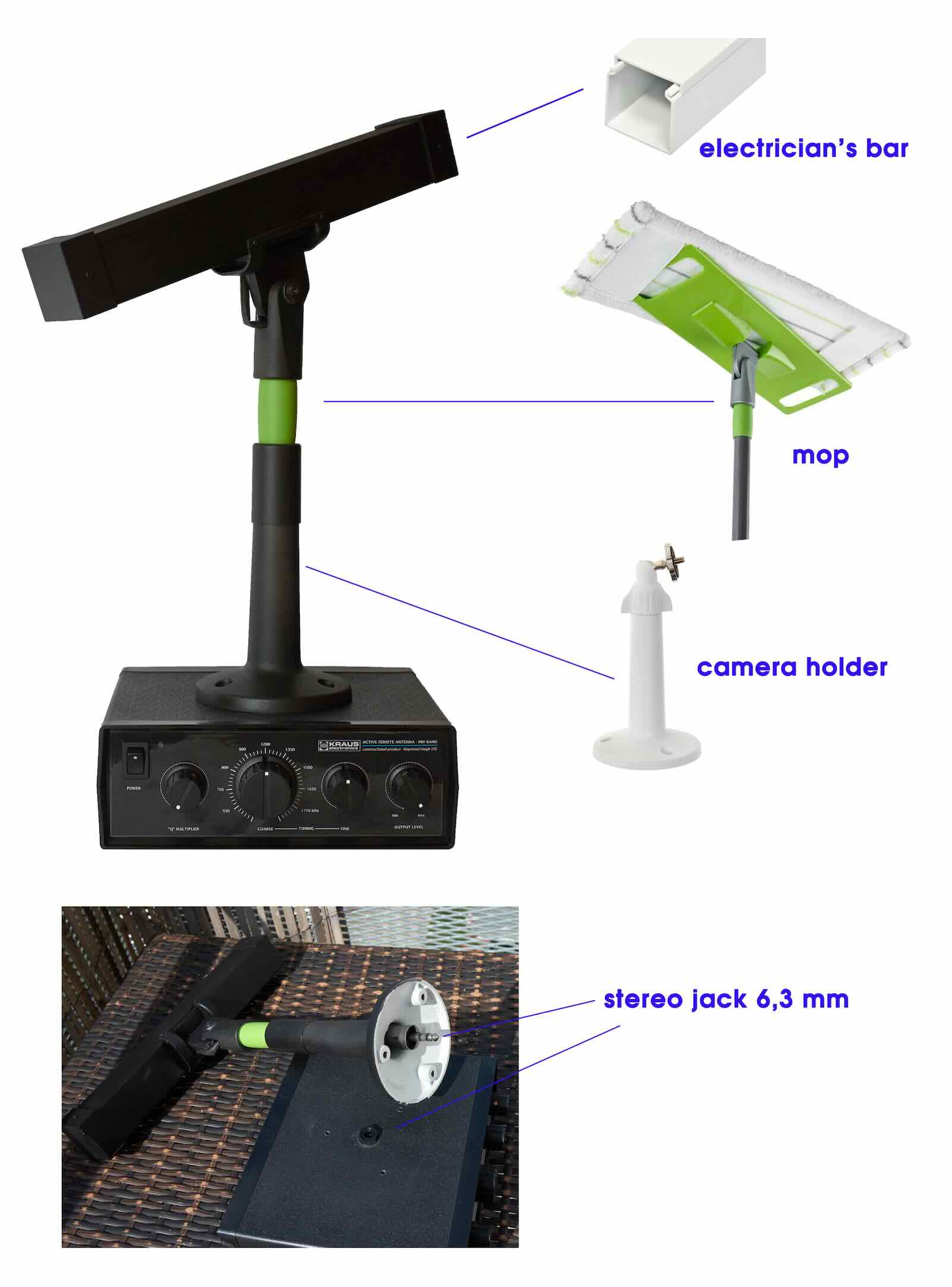
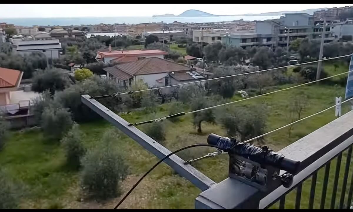
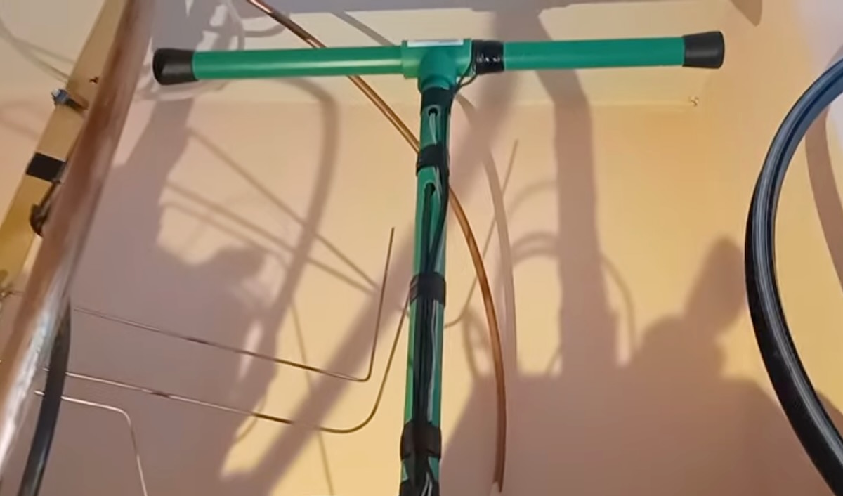
This is one of my builds from a few years ago: the T Ferrite antenna. It’s a minimal antenna designed mainly for mediumwave, but it also performs well on shortwave.
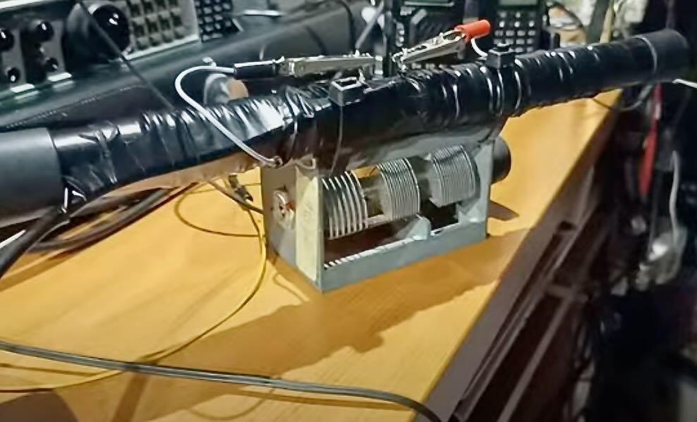
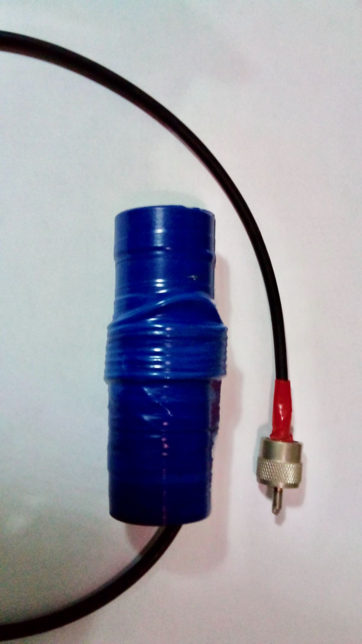
Inside the tube at the top are two 12 cm ferrite rods with 32 turns of telephone wire wrapped around them—this section is for mediumwave. Then, on the outside of the tube, I added four more turns for shortwave. A variable capacitor of about 1000 pF completes the circuit.
Shortwave is activated with an alligator clip. When the clip is removed, only the mediumwave section is active.
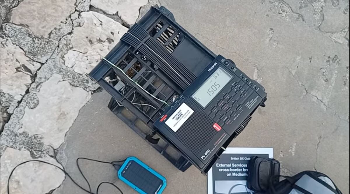
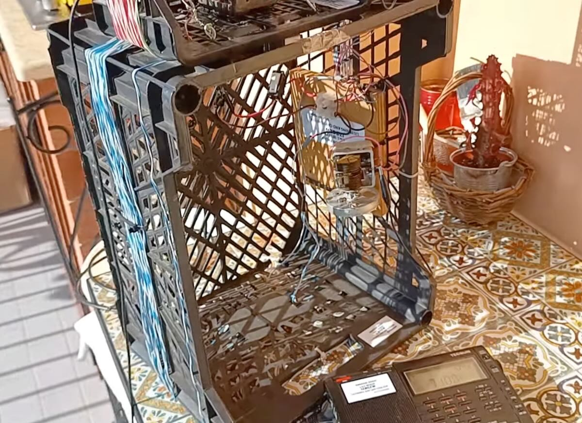
I tested this antenna with my old Trio 9R-59DS from the 1970s—a tube receiver still in perfect condition. To my pleasant surprise, the receiver paired beautifully with the antenna.
These tests were done on mediumwave in the early afternoon yesterday while it was still light outside. With the antenna placed above the receiver inside my shack, I was able to receive stations from across the Mediterranean basin and Eastern Europe, even in areas where the sun had already set. I really enjoy testing this antenna before evening, and I’m very satisfied with its performance.
You can see the results in this video on my YouTube channel:
I hope this will be of interest to the friends in the SWLing Post community.
Best regards to you and to all,
Giuseppe Morlè, IZ0GZW
We always enjoy checking out your homebrew antenna designs, Giuseppe! Thank you!