
 Many thanks to SWLing Post contributor extraordinaire, 13dka, who brings us Part Two of a three part series about the new SULA homebrew antenna project. This first article describes this affordable antenna and demonstrates its unique reception properties. This second article focuses on construction notes. The third and final article will essentially be a Q&A about the SULA antenna. All articles will eventually link to each other once published.
This wideband unidirectional antenna is an outstanding and innovative development for the portable DXer. I love the fact that it came to fruition via a collaboration between Grayhat and 13dka: two amazing gents and radio ambassadors on our SWLing.net discussion board and here on the SWLing Post. So many thanks to both of them!
Please enjoy and share Part 2:
Part 2: SULA Construction notes
by 13dka
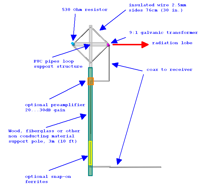
The drawing [above] has all you need to know. You basically need to put up a symmetrical wire diamond starting with a balun at the one end and terminating in a resistor at the other end of the horizontal boom, the sides are supposed to be 76cm/29.92″ long so you need to make yourself some…
Support structure:
I used 0.63″/1.6cm square plastic square tubing/cable duct profiles from the home improvement market to make the support structure. You can use anything non-conductive for that of course, broom sticks, lathes… The plastic profiles I used had the advantage of being in the house and easy to work on with a Dremel-style tool and everything can be assembled using the same self-tapping screws without even drilling. The profiles are held together with 2 screws, for transport I unscrew one of them and put that into an extra “parking” screw hole on the side, then I can collapse the cross for easy fit into the trunk, a rucksack etc.
![]()
These profiles are available in different diameters that fit into each other like a telescoping whip. This is useful to make the support structure variable for experiments and to control the loop shape and tension on the wire. The booms end up at 1.075m each, the profiles come in 1m length, so that’s 4 short pieces of the smaller size tube to extend the main booms by 37mm on each side
On the resistor end of the loop that smaller tube isn’t mounted in the “boom” tube but to the side of it in order to keep the wire running straight from the balun box on the other side.

Mast/mounting:
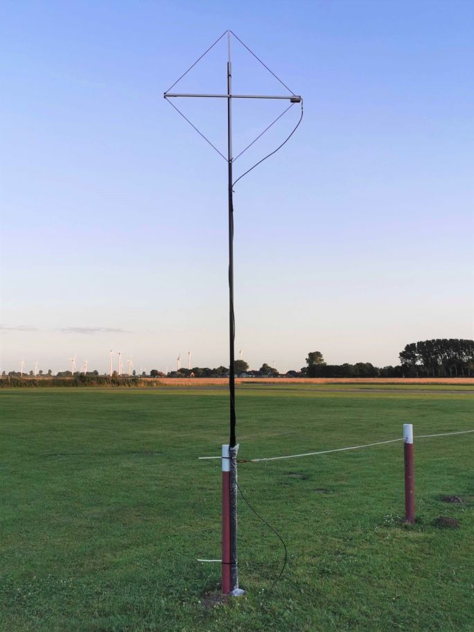
You can use anything non-conductive to bring it up to height. On second thought that is indeed bad news if you were planning on putting that up on your metal mast…and we have no data on what happens when you do it anyway. I don’t know if the smallest (4m) telescoping fiberglass poles would suffice for portable operation, but I’m a fan of just using the big lower segments of my 10m “HD” mast for the stiffness they give me (3 segments for the height, the 4th collapsed into in the base segment for easy rotation). Telescoping masts also give you easy control over…
Height:
The published patterns are for 3m/10′ feedpoint height over “average” ground. Increasing height further has no expectable advantage, instead it will deteriorate the favorable directional pattern of the loop. Flying it lower, or even a lot lower in windy weather on the other hand is causing a surprisingly moderate hit on performance.
Wire:
The wire should be 2.5mm diameter or (I think) AWG10, again, you can use whatever you see fit, I used flexible copper litz wire hoping this is a good choice for a mobile version of the antenna. Thinner wire may work too, but 2.5mm provides a better match across the entire SW range. Speaking of which, here are the SWR/Impedance curves for this version:

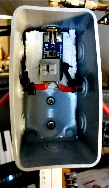
Balun/transformer:
The Nooelec “One Nine”-balun works fine, but it needs the R1 center tap connection cut to achieve galvanic isolation (which is a recommendable modification that can be easily undone). Please also see here: https://swling.com/blog/2019/10/the-nooelec-balun-19-v2/
You can also wind your own: Andrew writes “otherwise it can be wound on a binocular core just like the “NCPL” transformer but winding 2 turns to the antenna and 6 turns to the coax (winding ratio 3:1 which results in a 9:1 impedance transformation – the winding ratio is the square root of the desired impedance transformation ratio), the core may be a #61, #73 or #43 – but the transformer is important, since a bad one will ruin the antenna performance.”.
Resistor:
For the terminating resistor I used 4x 2.2kOhm and one 22 kOhm 1% tolerance metal film resistors in parallel to get A) as close as possible to 530 Ohms and B) to get a nice “pack” of resistors. The wire ends of the resistors can be twisted together, then generously tinned to form a pretty solid pack of resistors that has some mechanical robustness and removing the need for a box etc.. For easy testing of different resistors on the prototype I used luster terminals to connect the resistor pack, you should simply solder the loop wire to the resistor pack and apply shrinking tube to make it even more rugged.

Of course you can use any kind or size resistor except wire resistors but I recommend staying as close to 530Ohm as possible. Less resistance will make the lobes steeper while more resistance tends to form extra backside lobes or at least decrease the F/B ratio.
Current balun:
The optional “current balun” or “common mode choke” consisting of clip-on ferrites on the coax at the bottom of the mast is optional but highly recommended. It will help with both preventing the coax becoming part of the antenna and keeping noise away from the antenna. I could see once again how important that is when I compared the SULA with other antennas at the dike: While charging my Icom from a powerbank, the other antennas (without chokes) picked up some converter hash from that power bank, propagating over the coax up to the antennas, while the choked feedline to the SULA kept that away. Amazon has packs of 10 that should do fine, a row of at least 6 of them should go onto the coax.
Feedline:
Our attempts to have the feedline going to the balun via the horizontal boom (and also tucking away the choke there) resulted in reduced directionality and other bad results on some frequencies. Also, it made the weight-distribution worse, so don’t do that.
Upper row: Feedline inside the loop = bad. Lower row: Feedline outside of the loop = better
Price:
If you make your own balun and preamp and wait for the right scrap parts to show up you can save a lot of money but if you have none of the things needed and just want to source the most convenient options off Amazon etc., the total could rise to pretty substantial $150 or even more for the full system including coax and mast etc.. What you may get in exchange is a quite capable little beam antenna disguised as SML, with a performance profile promising some fun with the upcoming high frequency band openings between 15 and 6m. I’m looking forward to have this antenna up when the conditions are – for a change – slightly elevated again at the dike. At the same time I hope nothing goes wrong and everyone brave enough to make such an antenna (based on weird stories of some sleep-deprived OM) can find as much benefit in Andrew’s awesome design as I do.
The donut modification
The SULA derives its directionality from termination in the middle of the loop. But what happens if you replace the resistor with… thin air?
Top: Regular SULA. Middle: closed loop w/o resistor. Bottom: Air gap instead of resistor
As you can see, you get a nice donut-shaped and flat omnidirectional pattern like from a vertical with a good groundplane! In other words, the antenna still has its pretty low takeoff angle but now with good reception from all around. At the same time, the losses decrease and here’s maybe the most interesting part, the most gain increase is happening on LW and MW , while it retains its low angle profile! That doesn’t turn it into a MW DX antenna unfortunately, since directionality is an indispensable requirement for MW DX antennas but it’s certainly a great option to have when you’re not on the hunt for specific stations or countries, or when the DX station has a frequency all for itself.
You may have noticed the 3rd variant – the wires connected directly to form a regular loop. This might give you excellent NVIS performance and less of that pesky low-angle DX. Unfortunately, both variations will greatly mess up the formerly good impedance match and how exactly that is bad is yet another aspect of the antenna nobody has explored yet.
Here’s the link to Part 3: The SULA Q&A
See the March 2021 issue of QST which shows my design of a 2 x 4 foot portable flag for MF/HF radio direction finding. Same concept as being discussed above (terminated loop).
73, Don wd8dsb
Nice antenna, it looks like a the one I built, in use for Low Bands receiving.
This one:
https://www.ok1rr.com/index.php/antennas/9-the-w2pm-mini-diamond-receiving-flag
It needs a preamplifier of course, without one it just can receive very strong signal of several dB over S9… The polarization is vertical.
Anyway the S/N ratio is optimal for the low bands DX’ing on 40 and 80m, on 160m it’s not a good performer in my opinion.
It has good performances from 80m to 10m, mine is at 7 meters above the ground and 1 meter from my home roof, made of stone, height of the feedpoint.
Best Regards / 73
Franco IZ1RZO
To all; I invite all the people interested in building the SULA antenna, in need of further details, willing to ask further questions or just to further discuss the antenna to join the forum which Thomas kindly offered to the SWLing community and which can be found here https://swling.net/ I just started a new discussion on that forum exactly to carry on whatever SULA related topic which may emerge, you can find the discussion start here https://swling.net/viewtopic.php?t=55 feel free to post your questions/comments/… there
Thank you
To all:
I respectfully ask all the people which wants to further discuss the SULA (modifications, further infos, test results…) to join the SWLing forum https://swling.net/ which Thomas kindly made available to us and to post their messages in this discussion https://swling.net/viewtopic.php?t=55 this will be of great help, not only since the mail alert here on the blog never worked (at least for me) but also since there will be a common place where the infos/discussions will be connected
Thank you all !
What happens if you use 1/4″ copper tubing for the wire?
Mikek
At an educated guess, and based on previous modelling/experience with similar antennas, not much. In theory, signal level will be ever-so-slightly higher (due to slightly lower losses in the conductors and slightly lower conductor inductance) – but infinitesimally so because they’re both dwarfed by the source/termination impedances. Again, in theory, bandwidth will increase ever-so-slightly (again, due mainly to lower inductance) – but dwarfed by the fact that (a) bandwidth is already quite flat and broad (mainly because the antenna is significantly smaller than a wavelength), and (b) again termination resistance and source inductance dominates the inductance of the loop elements themselves.
While both signal level & bandwidth increases with increasing conductor diameter *can* be noticed in traditional electrically-small loops and also resonant-ish antennas, with this one I’d be very surprised if the difference was even noticeable.
I’ve previously run simulations using the SULA model and increasing the loop conductor diameter up to 5cm, running the simulation on 7MHz shows that the cardioid pattern almost disappears, to restore it we need to lower the resistor value to around 270 Ohm (if I recall it correctly) but then, with such a combo, the pattern is quickly lost going up in frequency so my opinion is that there isn’t any advantage nor reason to increase the loop conductor size
Here was my thought, I’m assuming we are matching the 450? impedance of the antenna with the 9 to 1 transformer. When you match, your output voltage drops by 1/2. When you open circuit it, the voltage doubles. My understanding is that’s a 6db gain.
Explain how I’m wrong on this. I’ve seen this with some of Dallas Lankford’s antennas.
It’s not wrong. But voltage isn’t the only thing to care about.
Something to consider: why care only about voltage? Why not current? Or power transfer – which is what one really wants* from an antenna, since maximum power = maximum signal? After all, maximum power transfer occurs when source and termination impedances match.
In an antenna there’s also secondary effects that arise from those (and other) relationships, and they’re often effects you want to maximise e.g. directionality/radiation/reception pattern. But It’s amazing how far even a simple understanding of basic principles like Ohm’s and Joule’s laws can get you…
(* Or, in most cases for receive antennas, minimum noise – which usually occurs not quite /at/, but /very close to/, the point of maximum power transfer…)
Re: lop amplifiers. What happens to the pattern if you unload the loop? As in use a high input impedance amp with a 50? output. You gain 3db, but what about the pattern?
Mikek
hi Andrew (grayhat),
as I am not familiar with 4nec2 i would like to know how you “described” the balun/transformer, the resistor and the choke in the sula.nec file. a link to a tutorial is also welcome!
I would like to run my own simulations and would like to be consistent with yours.
best 73
de
i2NDT Claudio
Not really a rhombic – the defining feature of those is being equal to or greater than 1 wavelength circumference, and a secondary feature is fairly acute (~45 deg or less) angles at the feed/termination end.
As noted on the loopantennas group, though, it **is** however nearly identical to a Beverage design/patent from the later 30’s / early 40’s. That covers the primary difference from the earlier rhombic (in his words, “diameter of the loop is substantially less than 1/4 wavelength” ); the only substantial difference between his patent and this antenna is that the patent specifically talks about a *horizontal* loop (since it was primarily designed for TV reception i.e. low angle, horizontally polarised).
For those interested, look at US Patent US2247743A…
Ron, thanks for pointing me at the “loopantennas” group; reading the comments there makes me think that someone didn’t understand the SULA, see, most people there compares the SULA with much larger antennas and seems to think that a loop will only be used on the lower frequencies, that isn’t the case, the SULA was developed in an attempt to have a small antenna capable of working honestly over (at least) the whole HF (SW) range (say 1MHz and above), while those larger antenna named on the “loopantennas” group won’t work well at higher frequencies, also, someone commented about “invention”, well, we never wrote we “invented” something, we just took a design and tried to optimize it, nothing else.
As for the patent, that was designed to work on a well given and limited range of frequencies, so while the SULA resembles it, I don’t think it’s the same
What else… oh, yes, if someone wants to play with the NEC model, it’s freely available on the SWLing.net forum, so one may just fetch it and play with it at will
If you prefer, here’s the NEC model, feel free to play with it
CM ———————————-
CM File: SULA.nec
CM ———————————-
CM
CM Small Unidirectional Loop antenna
CM
CM feed using a 9:1 balun transformer
CM keep the bottom corner at 3mt from
CM ground to avoid pattern distortion,
CM optionally add a 20…30dB preamp
CM
CE
‘ symbols definition
SY freq=7.100 ‘ test frequency
SY hght=3 ‘ height of bottom corner from ground
SY side=0.762 ‘ length of one side
SY diag=(sqr(2)*(side/2)) ‘ half diagonal
SY wire=0.00125 ‘ wire radius
SY vres=530 ‘ loading resistor value
SY segm=13 ‘ number of segment in wires
SY segs=5 ‘ short wires segments
SY wfed=1 ‘ feedpoint wire
SY sfed=segm ‘ feedpoint segment
SY wres=4 ‘ wire hosting the resistor
SY sres=1 ‘ segment hosting the resistor
SY drop=hght-diag ‘ coax drop section length
SY spac=(wire*5) ‘ spacing to simulate coax routing
SY dist=diag+spac ‘ spacing for coax feedpoint
SY coax=(wire*2) ‘ simulated coax radius
‘ wires geometry
‘ ID seg x0 y0 z0 x1 y1 z1 wire rad
GW 1 segm 0 0 hght -diag 0 hght+diag wire
GW 2 segm 0 0 hght diag 0 hght+diag wire
GW 3 segm -diag 0 hght+diag 0 0 hght+(diag*2) wire
GW 4 segm diag 0 hght+diag 0 0 hght+(diag*2) wire
‘ coax feeder “simulation” (may be changed to TL)
GW 20 segs -dist 0 hght+diag -dist 0 drop coax
GW 21 segs -dist 0 drop 0 0 drop coax
GW 22 segs 0 0 drop 0 0 spac coax
‘ ground parameters
GE 1
GN 2 0 0 0 13 0.005
‘ wires loading
LD 7 0 0 0 2.1 wire ‘ insulation
LD 5 0 0 0 58000000 ‘ copper wire
LD 1 wres sres sres vres 0 ‘ resistor
‘ enable extended kernel for calc
EK
‘ feedpoint
EX 0 wfed sfed 0 1 0 0
‘ initial test frequency
FR 0 1 0 0 freq 0
‘ end
EN
This is a scaled down version of a Rhombic Antenna. Check out designs on the internet.
They were a tad off in their load resistor build (4) 2.2K Ohm with (1) 22K in parallel yields 536 ohms, not 530 which is their desired value. Using a 15k instead of the 22k gets you 530.546 ohms which is virtually dead on. Normal resistor variations and selection could get you exact if desired.
Other than buying the 1:9 balun, ferrites & suitable wire AWG for loop, fairly simple design.
Hi Chuck! I bought a box of resistors off Amazon, containing only 17 different values and this was the closest I could get with what I had. 530 is the calculated target value, the actual “pack” measures 534 Ohms, however one-digit (and low 2-digit) offsets are certainly perfectly negligible.
Right so, keeping just “around” 530 Ohm will be fine, a shift of a few Ohm won’t cause issues, but a large change will, an example is here https://swling.net/download/file.php?id=94
Since the 10-foot height above ground seems to have quite an effect on performance
where (exactly) is the 10-foot point on the antenna
ie:
-the point at the bottom “V” of the wire
-the center of the antenna
-or ??
thanks
In this case the center of the antenna (which is also roughly the center of radiation and the feedpoint height), however a foot more or less will not make a huge difference.
Well, if you want to exactly follow the NEC model the 3m height is measured from the bottom corner of the diamond and the coax drops down the feedpoint for a lenght equal to a full diagonal (about 1m) where it reaches the support pole and the preamp
To be honest, I do not get what there is so special about this antenna. I have been building all kinds of T2FD’s, Flag and Lira antenna’s the past 2.5 decades. It is like re-inventing warm water. If you look around on the web, there are several designs in the same ballpark. This said, the 9:1 balun of NoElec is a bad performer. Better build your own. May I suggest building this with a Wellbrook FLG100ln amplifier in place of the balun at the feed point and change the resistor by a 450 Ohm value or a vactrol controller to get the most from this hardware design. And please do not run the coax parallel to close one of the sides of the loop (capacitance) as showed in the design.
Ron, the target for this small project was to find a receive antenna which could fit even in restricted space, and be easily built by anyone, hence the selection of commercially available components like the ones from NooElec, then by the way, nothing forbids one from picking different components or building his own.
That being said, I disagree with the idea of replacing the BalUn with a loop preamp and changing the resistor value, both the NEC modeling and the field tests show that doing that will change the antenna pattern and worsen the performances, and the same goes for chaging the coax routing; I don’t pretend that you trust my word on this, by the way, but I invite you to try the SULA “as is” and then modify it as you prefer and observe the results
Again, I’m not pretending that the SULA is “the ultimate antenna”, just saying that the design we came out with is the result of some months of experimentation/testing both with NEC and (thanks to Ollie) on the field
Hi Ron,
Adding to what Andrew said, the one thing that’s special about this antenna is the considerably smaller form factor that has practically no disadvantages, it is still in the same ballpark. It looks like none of the very similar but twice as big designs I learned about in this discussion is actually better, besides a few dB less losses on MW.
The form factor also means losing some of the mechanical complications of similar designs, a small packing size for portable operation and easy deployment: Any construction element exceeding 1.10m won’t fit into my tiny European car w/o backseats. ::D This thing does fit and it doesn’t really need assembly, just screw in the second boom screw, hook in the wire, done.
The electrical trunking you use is available in the UK in various lengths, including x 3 m from wholesalers/electrical specific suppliers. I feel sure this may be so elsewhere.
@Don
No cigar, the design in QST “seems” the same but isn’t; there are some pitfalls which we avoided/solved with the SULA; the larger size of the QST loop means that it “may” work a bit better at lower frequencies, but going up in frequency the pattern will loose its characteristics, also the folk at QST failed to consider the effect that the coax routing has on the antenna pattern, so again, the SULA is a different kind of beast 😀
@Mike
Thanks, but see… those are LOOP amplifiers, the SULA doesn’t need them since due to the BalUn at its feedpoint (and the resistor), the SULA presents an impedance around 50 Ohm over the whole range, so the preamp used may be whatever LNA accepting a 50 Ohm input from the antenna, no need for “special” preamps designed to be connected to loop antennas 😀 so a normal LNA offering 20dB (or more) gain will just fit
Very good !!!
Thanks.
Essentially the same loop was featured in QST back in early 2021 as a noise df’ing loop, written by WD8DSB. Pretty deaf without lots of preamp. Fine for the purpose he built it for.
https://sites.google.com/site/portableflagantenna/home
Has anyone else commented yet on the 10 AWG Litz wire? The narrative talks about this, I think I saw a photo caption with it. I could be wrong, but I can’t imagine that’s what they used.
KB2DAJ
Hi Steve,
Thanks for that! Indeed, 10AWG would be 5mm^2 and not the 2.5mm^2 we used later, which would be roughly 13AWG. The sentence should read “The wire should be 2.5mm^2 cross-section or AWG13,”
For those wondering, this is a variant of the flag/pennant antenna style.
See https://www.qsl.net/wa1ion/flag/flag_antenna.htm
https://www.angelfire.com/md/k3ky/page37.html
And look it up in various other publications, such as the ARRL Antenna handbook.
My question is how did the author(s) arrive at this particular resistor value? Was there any testing done, or was this just from the models?
Hi Jake,
530 Ohm returns the best horizontal pattern in the simulation and I tried 1kOhm, out of curiosity 220Ohm and later a 760Ohm “pack”: Even with 760 Ohm the minimum was so degraded that I didn’t bother exploring this further/with finer granularity, also based on the fact that this result was just another instance of the actual antenna’s matching the predicted behavior surprisingly well.
We have a number of loop amplifiers listed here…
https://wiki.radioreference.com/index.php/Loops#Loop_Amplifiers.2FKits
Mike
Oh, this is good. Thanks!