
 Many thanks to SWLing Post contributor extraordinaire, 13dka, who brings us a three part series about the new SULA homebrew antenna project. This first article describes this affordable antenna and demonstrates its unique reception properties. The second article will focus on construction notes. The third and final article will essentially be a Q&A about the SULA antenna. All articles will eventually link to each other once published.
This wideband unidirectional antenna is an outstanding and innovative development for the portable DXer. I love the fact that it came to fruition via a collaboration between Grayhat and 13dka: two amazing gents and radio ambassadors on our SWLing.net discussion board and here on the SWLing Post. So many thanks to both of them!
Please enjoy and share SULA Part 1:
Introducing the Small Unidirectional Loop Antenna (SULA) 1-30MHz
A small and simple, unidirectional and DX-capable loop “beam” for SWLs!
by 13dka
In early June, Andrew (grayhat), SWLing Post‘s resident antenna wizard suggested a variation of the “cardioid loop” on the SWLing Post message board: The original “cardioid loop” is a small loop receiving antenna deriving its name from a cardioid shaped (unidirectional) radiation footprint. The design is strikingly simple but it has a few downsides: It relies on a custom preamp, it needs a ground rod to work and it is unidirectional only up to 8 MHz.
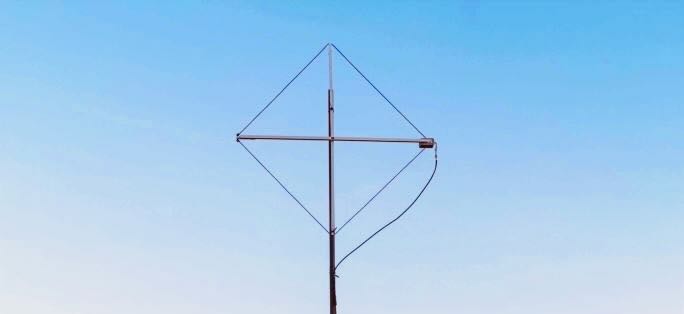
Andrew’s version had the components all shuffled around and it did not only lose the ground rod, it also promised a nice cardioid pattern over the entire shortwave, from a small, diamond shaped loop. Wait…what? It can be made using parts available on Amazon and your DIY store:
You need some 3m wire and PVC tubes to create a support structure to hold the wire, a 530 Ohm resistor and a 9:1 balun like the popular “NooElec One Nine”. Since it’s a “lossy” design, adding a generic LNA like the NooElec “LANA HF” would help getting most out of it. When you put that all together you have what sounds like an old shortwave listener’s dream: a small, portable, tangible, and completely practical allband shortwave reception beam antenna with some more convenient properties on top, for example, it is a bit afraid of heights.
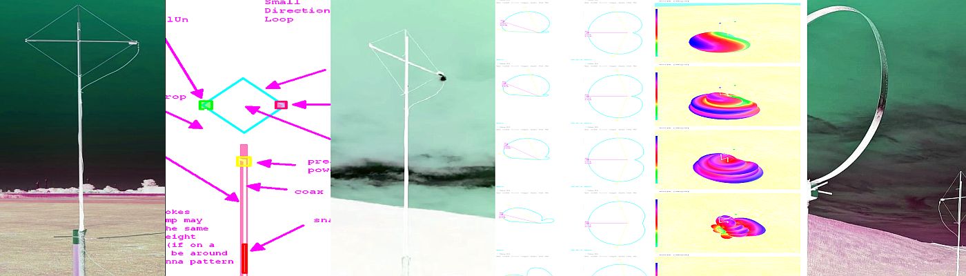
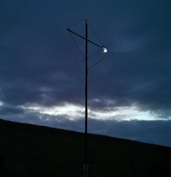
That sounded both interesting and plain crazy, but the .nec files Andrew posted were clearly saying that this antenna is a thing now. Unfortunately Andrew suffered a little injury that kept him from making one of those right away, I on the other hand had almost all the needed parts in a drawer so I ended up making a prototype and putting it through some of its paces, with Andrew changing the design and me changing the actual antenna accordingly, then mounting it upside down. Let me show you around:
- Small, diamond shaped wire loop (with 76cm/29.92″ sides), needing as little space as most other small loops.
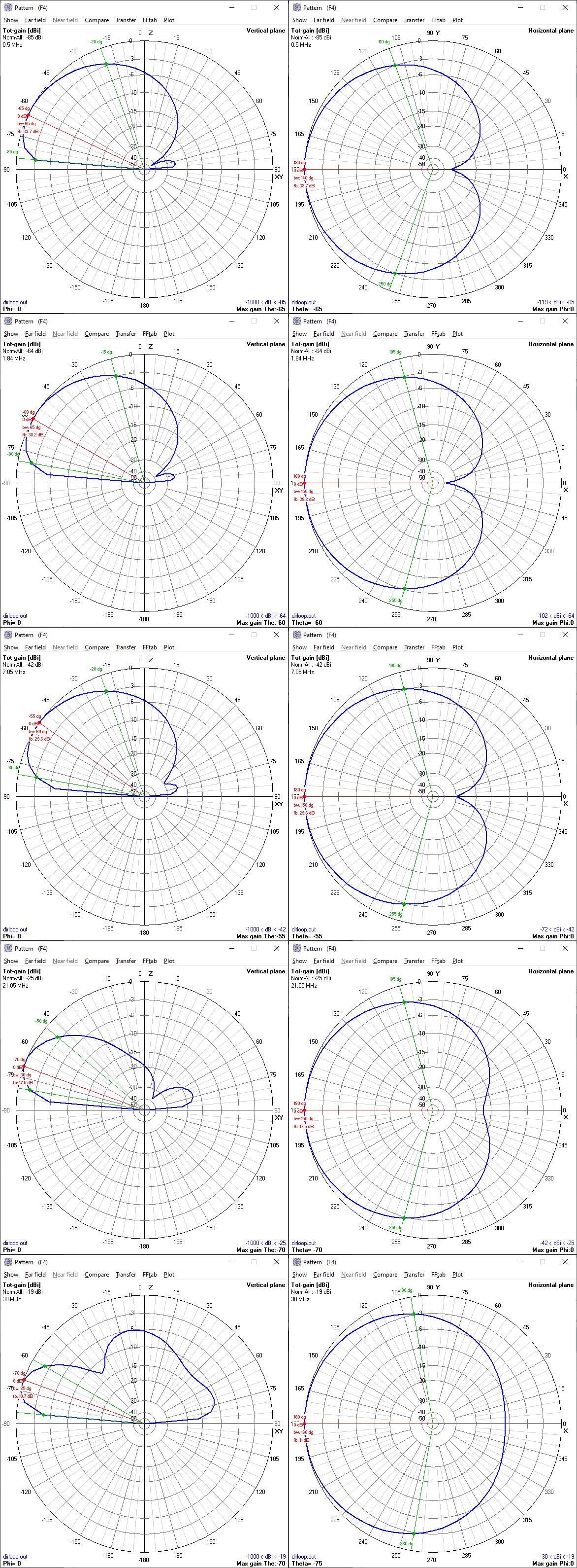
- Unidirectional with a ~160° wide “beam” and one pronounced minimum with a front/back-ratio of typically 20dB over the entire reception range 1-30MHz.
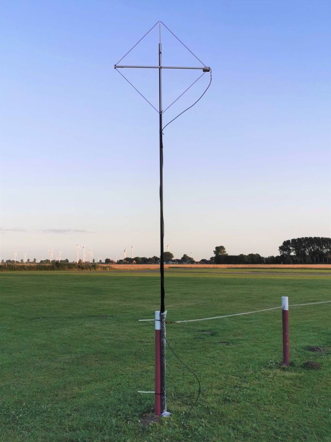
- Moderate height requirements: It works best up to 3m/10′ above ground, where it gives you…
- …a main lobe with a convenient flat takeoff angle for DX
- Antenna is comparatively insensitive to ground quality/conductivity.
- Wideband design, works best on shortwave and is pretty good up to 70cm.
A functional small beam antenna for shortwave reception that’s just as small and possibly even more lightweight (prototype:~250g/9oz) than your regular SML, that can be easily made out of easy to obtain parts and easily carried around for mobile/portable DXing and due to its cardioid shaped directional pattern also for direction finding, a “tactical” antenna that’s also doing DX? Unlike conventional, Yagi-Uda or wire beams it can achieve a low takeoff angle at only 3m/10ft height or less, the front/back ratio is typically better than that of a 3-element Yagi, with a particularly useful horizontal pattern shape. That it’s rather indifferent to soil quality could mean that more people get to reproduce the good results and being a real wideband antenna is making the SULA an interesting companion for multiband radios and SDRs. Really? A miracle antenna? Is it that time of year again? If I had a dollar for every….
The proof is in less than half of the pudding
Full disclosure: I’m not an optimistic person.
Of all the things I expected to happen, that it actually works was not the top one. But let me just share with you how it greeted me out in the field, the first thing ever recorded from such an antenna at the dike (sorry for the video orientation):
This was the first time ever I heard a small pile-up of specifically Japanese stations out at the dike, calling for lovely sounding TF/LA5MUA in Iceland. That I had the new antenna turned a bit towards Japan may actually have contributed to that specificity. These signals came in with a comfortable SNR, and this was only the passive version of the SULA (I forgot to bring the power bank for the preamp that night). Most importantly this didn’t sound “meh” at all, which was what I expected more than anything else – that it kinda works but it’s too “meh” to bother with. Rarely been more happy to be wrong! After changing the feedpoint to “outside the loop” for improved lobe shape and stability, the real SULA confirms the 4NEC2 simulation in most if not all of its predictions, it…dare I say that…it works!?
Video: checking directionality on 40m
Expectations need to be reasonable of course, beam antennas are not like flashlights, the highest difference in “brightness” between front and back is 1-3 S-units, even though the SULA has the potential to be better than that. Let’s also not forget that this is a quite lossy antenna, that’s why it may not work well for many radios without adding a preamp to the antenna, and even with that help it will not have super hot levels. What we hope for is that it can yield a better SNR from its smaller reception lobe compared to regular loops of that size, and the evidence collected so far indicates that this is very often the case, sometimes more, sometimes less…
Note: Brighter waterfall background = ML-200, darker background = SULA
The key information you’re all probably waiting for is where on the big roster of antennas this one could be sorted in and after only 4 weeks in chronically disturbed conditions here’s some mostly speculative performance ballpark guesswork – the overall performance of the preamplified version is comparable with ideal results from regular, high quality active loop antennas of comparable size, but the SULA offers some potential perks over them.
Whereas “Ideal results” for an SML are what the ML-200 is picking up at the beach, because it’s close enough to the water to have good low angle coverage. The more you move away from the water, the more the results are supposed to drift apart in favor of the SULA. But even with a preamp it’s pretty much deaf on LW and still quite insensitive on the lower part of MW…and that still brings us right back to the good things:
Directionality
Video: Separating BBC and Radio Romania on 909kHz (Indoors)
Even down on MW it has a pretty deep minimum on the backside that can be used to separate pretty strong AM stations on the same frequency and it generally works pretty OK at night on MW. Beyond 1 MHz it opens up and starts doing what it says on the imaginary tin. The pronounced backside minimum (to avoid the term “null”) is getting flatter with increasing frequency but it has still excellent (>13dB) directionality up to 10m and beyond. This is pretty educational, too: All of a sudden I can tell if a signal comes short path or long path and an azimuth map is my new friend. That’s fun!
SDL Radiation
As a pseudo-practical example, here’s how it sounded when I accidentally turned the back of the antenna through the loudest station in a pile-up (IU5PTB). Note how a station from Belgium suddenly comes through. There’s no QSB on the Italian station, I was just obsessed with fading him in and out with the antenna, nothing personal either. 🙂
Up in the FM band the pattern changes due to the loop becoming a “big” (1 Lambda) loop for the wavelength and the unidirectionality makes place for a bidirectional pattern shifted 90°, which is then perpendicular to the plane of the loop. The loop stops having losses and if you have nearby FM transmitters you may need to add an FM bandstop filter in order to avoid overloading the LNA, that the SULA is a surprisingly competent antenna on FM, VHF and beyond for its odd 3m restriction is probably not helping with that.
Video: Early morning 137 MHz satellite band vs ML-200.
Elevation/takeoff angle and height
Again, this antenna works up to 3m/10ft of height, more will quickly deteriorate the lobe pattern. At 3m/10ft the takeoff angle is typically centered at 25° on 20m, lowering the antenna to 1.5m/5′ makes that 30°, 5m/15′ would yield 20° but at the cost of directionality. Mind you, 25° is only the gain peak of the lobe, the 10° takeoff angle is there too and only a few dB quieter over average ground.
The takeoff angle of the SULA still depends a bit on frequency as in “higher=flatter” but the slightly steeper angles on the 160-40m bands at constant 3m height are rather welcome variations catering for the different usage of the 80- and 40m-band . The best is maybe that this behavior is all “wideband”, with similar properties on all bands and all frequencies on shortwave.
This video is an unlucky pairing of an amplified YouLoop with the SULA, trying for RNZ after sign-on on 15720. It was made to illustrate the newly discovered, surprisingly steep angles at the dike for the (amplified but unmodified) YouLoop, disqualifying it as an antenna to compare with the SULA. What remains is the recording of what is basically a “steep angle/flat angle” demonstration with one of the world’s favorite DX stations, admittedly making the SULA sound inappropriately better.
Video: Antennas must receive RNZ or they officially suck
BTW, this is Auckland VOLMET on yet another morning with thoroughly messed up conditions, USA skip severed, no signal from WWV but Auckland comes in long path.
Video: ZKAK with uncool propagation…long path (July 30th) (Direct Audio Recording)
The low height requirements are making this great for portable operation on short, portable fiberglass poles or for permanent installation in small backyards. Obviously you can turn its main lobe away from your house for some attenuation of QRM from the house. For the same reason it could be good on a balcony, depending on the noise situation of course. It probably only kind of works indoors or in the attic, this may not be the ideal indoor antenna in very noisy environments, or when the relative height of the antenna is too high, or just because the patterns may be all pretty off indoors. OTOH, mounting this 3m high over a big metal roof on a high-rise could be pretty awesome…
Another nice trait of the SULA is its relative independency from ground properties – the difference in takeoff angle between “good ground” and “poor ground” is only +/- 5° (10° flatter near salt water), so in theory it could bring in some DX where other antennas would have great difficulties to do that. Whether that’s true or not…that’s for you to find out!
So far we only verified some basic properties of the SULA on open area test sites, there’s only one of these antennas in existence right now…and building your own would be a chance to explore something (I think) new and if you’re inclined to, share your results!
Everyone would be super interested in practical demonstrations, particularly comparisons with other antennas and performance in different environments!
Stay tuned for Part 2: SULA Construction notes!
We will post Part 2 of the SULA antenna series within the next few days. Once posted, we will link to it here. You can also follow all three parts of the SULA series by bookmarking the tag SULA Primer. Edit: Here’s the direct link to Part 2!
Now I have something to build when solar flares wipe out the HF bands, the repeaters are dead and its raining.
You can roll it up and toss it in the car for some portable listening from the park
Or to try using as a receive antenna on the low bands
The rotator at $200 makes it a $220 project
A loop with a resistor to produce a unidirectional pattern was patented by Harrold Beverage in 1941, since then the idea has been periodically “re-invented” by many individuals but the idea is very well known to people interested in Antennas. You can find the original patent at US 2,247,743, Beverage applied for the Patent in December 1938 so the examination took some time!
So when People claim to have discovered or invented the idea they are too late or ignorant of the history. No one mentions the true originator although his very long wire on or just above ground is normally regarded as THE Beverage antenna.
Basically the added resistor is opposite the feed point ( it can be elsewhere though), the loop then becomes sensitive to the electric field as well as the magnetic. When the resistor is added the original two nulls are filled in, at 90 degrees to the notches a new minima appears as the magnetic and electric fields partially cancel, increasing the resistor leads to a deep null when the two components cancel. At this R value the cardioid ( heart shaped) pattern is formed, at 90 degrees the former notches are replaced by a unity gain, 180 degrees from the null is a double level broad peak. It is a very simple pattern to calculate for an angle a ( for a small loop), the base figure of 8 is A= Cos a, the combination is A=1 + Cos a as the vertical e-field component is omnidirectional ( 1 for any angle).
This is not a miracle antenna, it’s simple physics in action. The resistively loaded loop IS e-field sensitive!! so the advantage of e-field noise suppression is lost. One interesting application is as part of a very directional array. C & S Antennas used a cardioid R loaded broadband loop with an active amplifier as elements in an array to produce broadband directivity for Mil and Com applications. It’s also been very widely used as a handheld DF antenna by R & S. Triangular and rectangular loops with resistors are also well known. Nothing new at all!
73, Alan G8LCO
Hi Alan,
First off, thank you for the historical background, we have read this with big interest in the loopantennas.io group! However, the three-part article does no claim invention of the terminated loop principle or anything and re “miracle antenna”, the third part literally says…
“In summary, this is not meant to be a miracle antenna, just number of compromises re-arranged to create a particularly uncomplicated, small, unidirectional loop antenna that aims for DX, for apartment dwellers and DX nomads like me.”
Andrew basically played with many existing ideas in NEC to find a way to make a particularly simple and portable unidirectional antenna that can be made with particularly easy to obtain parts that many of us already have. What he came up with turned out to have some traits that similar designs don’t have in this combination – it’s smaller, offers a low elevation, cardioid pattern over the *entire* shortwave and maintains that over a wider variety of heights and ground properties. Since it’s so simple to make one, we considered this a worthwhile project to present particularly to people who are not regular antenna builders here on the SWLing Post. We certainly did not mean to offend anyone by doing this.
BTW the Beverage patent describes a horizontal, terminated loop antenna for TV reception and while it basically has the same basic shape and components, it was designed to cater for an entirely different purpose. This is not meant to belittle the amazing achievements of Harold Beverage but we are all standing on the shoulders of giants and only experimentation, taking old ideas and thinking them over again and again is leading to progress.
73s,
Ollie
I’m not sure what to make of this. The computer models for it predict -40 to -80 dbi off the main lobe from 0.5-7Mhz, the meaty part of shortwave and AM dx. That’s horrible. In real terms, the signal coming out of this antenna into your radio is on the order of 1000 to 100,000 x weaker than a simple wire dipole cut for these bands. At the same time, I can’t really argue with these videos – the BBC vs R. Romania is pretty impressive.
Also, receive-only antennas aren’t nearly as fickle as transmit antennas, so maybe these horrible numbers don’t mean much in radios with decent sensitivity and low internal noise. Maybe one way to improve the signal strength would be to get a better match into the rig with a tuner-even though this would likely mean you’d need to adjust the tuner for each band (probably would take 10 sec to do that).
That’s common for all the now pretty popular “lossy” antennas, the idea is to trade gain and the ability to transmit for a better SNR and/or smaller size and compensate for the tremendous losses by means of modern LNAs. Since the SULA already provides a wideband match to 50 Ohms inputs, a tuner will likely not provide any more level, at the risk of deteriorating the directivity the SULA was made for.
How would this operate if the loop was horizontal? Are there any advantages/disadvantages to running it horizontal vs. vertical?
The polarisation of the transmitting and receiving antennas need to be identical for maximum signal strength.
Many medium frequency transmitters use a vertical antenna, where as high frequency broadcasters also use curtain arrays which are horizontally polarised.
When a signal reflects off a surface or a variation of air density the polarisation rotates.
Sounds interesting I like experimenting with loop antennas
John vk3egg
Unidirectional means one direction, bi-directional means it is sensitive in opposite directions but not at the sides.
A Yagu-uda antenna is unidirectional because it has an active element which is like what you have, but there is a reflector behind it to stop reception from behind. Directors in front focus the beam.
So for your antenna this is physically very large on a beam because of the longer wavelengths used.
Tried something similar a couple of years ago for the BCB, Three turns , diamond shaped, 1.5 m width/height. Matching transformer and pot on the 2nd turn connected as for the single turn version. Used a matching transformer into twin lead (not coax, cheap figure 8 stuff) to the receiver. Pot set for best null to the rear. Worked very well into a preamp at the receiver end – matching transformer 2:1 ratio at the preamp input (100:50 ohms.). With a balanced feed, no chokes should be necessary as is needed with co-ax. The feed was along the horizontal arm to the center, then 90 degrees down and off to the receiver.
This was a nice, quiet antenna with good directivity. The self capacitance of the 3 windings would have determined the upper frequency limit, but I was interested in the MW band mostly. Easy to build, cheap and effective and a bit better than the cardioid mix of a loop and whip in rejecting high angle stuff from the rear. Note: I have found that setting the null is best when the total system is in place ie when everything from antenna to receiver is connected. This has been found to be the case with K9AY, EWE antennas as well. A friend to help you is very advantageous!
A unidirectional null wideband antenna of small size that performs well over varying ground conductivity is an impressive achievement !
I am wondering how deep is the null in the real world?
The old PalomarEngineers electrostatically shielded 1 to 15 MHz amplified loop antenna
had steep bidirectional nulls. Is the SULA null of the same depth?
The Kiwa Pocket Loop has pretty good bidirectional nulls on shortwave,
and by “off tuning” from the resonant point you can vary the signal gain.
Is the SULA null deeper?
Interesting new antenna.
Thanks for the extensive development work.
The “null” depth depends from frequency, the F/B ratio on some bands may be as deep as 30dB, to make an example, this means that if the antenna main lobe gain is (say) 0dB, the “null” will attenuate signals by -30dB, I don’t have the data at hand at the moment, but you can find the NEC model on the SWLing.net forum and play with them at will
The minimum F/B ratio seems to be 13dB on 10m, 17dB on 15m, 20dB on 17m, 22dB on 20m, 26dB on 30m, 30dB on 40m and 80m and 38dB on 160m.
Ok; set aside the TL;DR 🙂 … if you can, give it a spin, maybe as an rx antenna coupled with a tx one 😉
I believe what was tuned in about 137.62 MHz was NOAA 15, so the loop appears to work well enough to hear LEO satellites, too.
Yes, that was a NOAA bird and earlier its telemetry transmitter, plus some Orbcomm sats. That all sorts of antennas receive the 137 sat band pretty fine isn’t unusual, what I wanted to show is also how much worse the ML-200 (when the waterfall gets yellow/green) performs in terms of SNR. That and the flat pattern would make sure that the signal can be picked up as soon as the sat rises above the horizon but it if I’d actually want to decode the picture APT I’d probably use an omnidirectional antenna though.
Gold.
I am so looking forward to the rest of this series as well as building the antenna.
“Do a search on Ebay or Aliexpress for keywords “HFDYloop Wideband Active Small Magnetic Loop Antenna”. The price is around $45 USD.”
I’ll try one as soon as they are available from Amazon, fulfilled by Amazon that is.
Sounds too good to be true though, but I love being wrong. LOL
I might have to build this to try out as a ham receive antenna. Swl too!
I am sooo looking forward to the rest of this series!
Excellent collaboration, 13dka and Andrew! I’ve read through your entire swling.net forums discussion and learned a lot.
An alternative, reasonably priced amplifier could be a recently introduced amp (as part of a kit with antenna coax and other hardware). Do a search on Ebay or Aliexpress for keywords “HFDYloop Wideband Active Small Magnetic Loop Antenna”. The price is around $45 USD.
This amp has been discussed on the loop antennas groups.io forum, and it is supposed to be built to the highly regarded LZ1AQ design. The LZ1AQ heritage is the reason this one may stand out above other low cost amps.
On the topic of small, unidirectional loops, have you seen this one from UK’s Cross Country Wireless? http://www.crosscountrywireless.net/cardioid_loop_antenna.htm It’s interesting it has the amplifier and termination resistor in the vertical plane, not horizontal.
Thank you Guy! Also thank you for the preamp suggestions, this is one area where it could be worthwhile to check out the alternatives, or – considering that SNR is all this antenna is about – spending the extra dollar for just a smidge less noise. 🙂 Re the CC Wireless loop page, that describes a replication of the original C&S Ltd design (with the ground rod) using the CCW loop amplifier.
Thanks for that further information… I missed the reference to the C&S design when I came upon CCW’s page, and also overlooked the grounding requirement. Your SULA looks to be well suited to both home and field (DXpedition) use!
At home I have a ALA1530LN (newest version) on a rotor… it may have to step aside for a SULA for experiments! One 15-18 dB preamp I have on hand is a very robust one that I salvaged from a Wellbrook K9AY control box many years ago. This could work well with the SULA.
I’d be pretty curious on a comparison between the ALA1530LN and the SULA, particularly above 10 MHz! 🙂
(Background; Among all the SMLs there are only few actually tuned to be good on shortwave beyond 10 MHz, IIRC the ALA1530LN is said to be one of the exceptions. Of course, on MW the SULA can’t hold a candle to the Wellbrook, except maybe when your location is perfectly aligned between a station and a QRM source.)
couple quick notes; the SULA does NOT neet a loop specific preamp, any preamp accepting an input impedance around 50 Ohm will just work
As for the CCW cardioid loop, that one heavily depends from the kind of ground it’s installed on and requires a good ground connection, the SULA overcomes both limitations
to conclude, I invite anyone willing to discuss to the SWLing forums where we’ll be able to extensively discuss this topic…. and others, by the way 🙂
“As for the CCW cardioid loop, that one heavily depends from the kind of ground it’s installed on and requires a good ground connection, the SULA overcomes both limitations”
This is the reason I never tried the CCW cardioid loop, I’m a big “fan” of ground independent antennas.
Yes, I’m handicapping myself big time with my “personal choices”, things like ground independence and ground mounted/low height antennas, no active components at the antenna, or bias-t power feed, but it’s still fun and a challenge.
I follow the Einstein principle though, things should be as simple as possible but not simpler. LOL
This is a scaled down version of the W2PM Mini Diamond Receiving Flag antenna, which was based on an idea by K6SE.
I have been using one for some months now. It’s far and away the simplest, easiest to build, most affordable, and effective HF RX antenna I’ve ever built and used. As a matter of fact, unless I move houses, this is it for me as far as an HF RX antenna is concerned.
The description for the W2PM implementation is found here:
https://www.ok1rr.com/index.php/antennas/9-the-w2pm-mini-diamond-receiving-flag
I exchanged a few emails last year with Chris of Cross Country wireless, and he confirmed all the simulation results and built one to test. He was so impressed with its performance that he said he was going to offer an amp for it. COVID and supply issues got in the way and the release, if still planned, is delayed.
I had the same idea of a scaled down version, and am in the process of building one with, believed or not, the same specs. I can now proceed knowing that the idea is sound and that it’s going to work.
As an aside, with the W2PM version and either an AirSpy HF+ Dual Port or Discovery, a pre-amp is not needed.
I have been promoting this antenna since I built mine, but this post on SWLing.com will give it a lot more exposure. Kudos to both Grayhat and 13dka.
I think it’s a good idea to route the coax to the centre of the square/diamond and then down. This is what I did, just in case there is some negative interaction with the coax exiting from the side.
If you check out the forum pages for this design evolution (link below from Andrew), you’ll see that antenna simulations were compared with coax down the center versus off to the side. The side location provides better reception pattern and nulling.
Thanks, Guy.
I’ll check the forum pages for the design evolution and give it a try.
Just checked the design evolution of the SULA… wow…they did a lot of work there. Excellent job, guys!!!!
I did not save my notes or the emails I exchanged with Chris at Cross Country Wireless, but looks like the reduced size of the SULA makes it more ‘delicate’, compared to the W2PM version.
If I recall correctly, the W2PM was pretty much height insensitive, the pattern did not change. I prefer to keep antennas at a low height, or reachable with a small step ladder. My TX verticals are ground mounted as well.
Since I did not use a pre-amp at the antenna, only an impedance transformer, ferrite clamps/toroids did not make any noticeable difference. That said I do have CMCs in the radio room.
My preferred option these days is to avoid any active components/modules at the antenna. In my experience, the trouble of making active components/modules resistant to the elements, plus bias-t power feeding, are not worth the trouble.
Thanks. Before fall camping (and antenna experimentation) begin, I’ll have to build one.
here
https://swling.net/viewtopic.php?p=411#p411
the 9:1 balun is the NooElec v2, the preamp is a LANA HF barebones, add a bias tee or a battery pack for the preamp, some snap-on ferrites and you’ll have the base, the coax, wire and the other stuff can be sourced locally
by the way, nothing forbids one from building the balun and/or the preamp 🙂
Regarding the LANA HF amp, for a little more $$ a cased version is also available, and it includes a micro USB to barrel pigtail. This way one could use a linear regulated power supply/wall wart instead of cheap switching wall warts.
I had the barebones version and liked the power feed options, but the design really calls for 5 VDC operation for longevity. This low voltage on the other hand may limit its efficiency (gain, SNR).
The other downside of feeding it with 5VDC is that most users will likely use a cell phone power adapter. These can generate more noise than one can imagine.
For 5VDC a cellphone battery pack, available at dollar stores, is the way to go. This would be the option for portable use as well.
I’ve been building and using these antennas on 160 and 80 meters for about 15 years. They work well as a broadband receive antenna.
This looks an awful lot like a scaled down version of the terminated loop antennas (flag, pennant, kaz, etc) that MW dxers have been using for a long time now.
similar, not the same, we’ve put some work in optimizing it and making it easy to put together for anyone
Looks like a micro Rhombic to me. I have experimented used horizontally with those on FM at 1/2 WL per leg and 1/4 WL per leg. Extremely directional but low gain. I did not use a preamp, and I am no expert and have no formal electronics education.- FARMERIK
The difference between this and a rhombic is that a rhombic is a resonant antenna while this one is wideband and a rhombic’s beam is a lot narrower and pointed in the opposite direction.
Another great job 13dka! As you have been aware of my RFI issues for a while, I’m looking forward to parts 2 and 3 before I proceed. Actually looks like something I could do. 🙂
—
Mike
Well, Mike, if you want to go straight on and build it, you can find all the details (and the whole “evolution” of the SULA design) here
https://swling.net/viewtopic.php?t=47
the latest version design can be found here
https://swling.net/viewtopic.php?p=411#p411
as you see, nothing too complex and all pieces may either be easily bought or, if one prefers, built
Ok, the cat is out the bag now 😀
Thank you for putting all this together, I’m by far NO “good writer” and you exposed the whole thing very well !
Now it’s up to the readers
See the March 2021 issue of QST which shows my design of a 2 x 4 foot portable flag for MF/HF radio direction finding. Same concept as being discussed above (terminated loop).