Shortwave listening and everything radio including reviews, broadcasting, ham radio, field operation, DXing, maker kits, travel, emergency gear, events, and more
Many thanks to SWLing Post contributor, Mark (M7MHY), who shares the following review:
Impressive Pocket Performance!
‘Shirt pocket’ radios are one of my favourite aspects of the hobby. For me, nothing quite beats the enjoyment of cruising the MW band (and a little SWLing on radios that allow), with a tiny, generally inexpensive unit and pushing the boundaries of what is possible with these receivers and their mini-sized internal ferrite bars. I think there should be another subsection of the ultralight category to accommodate such radios – “super ultralight”!
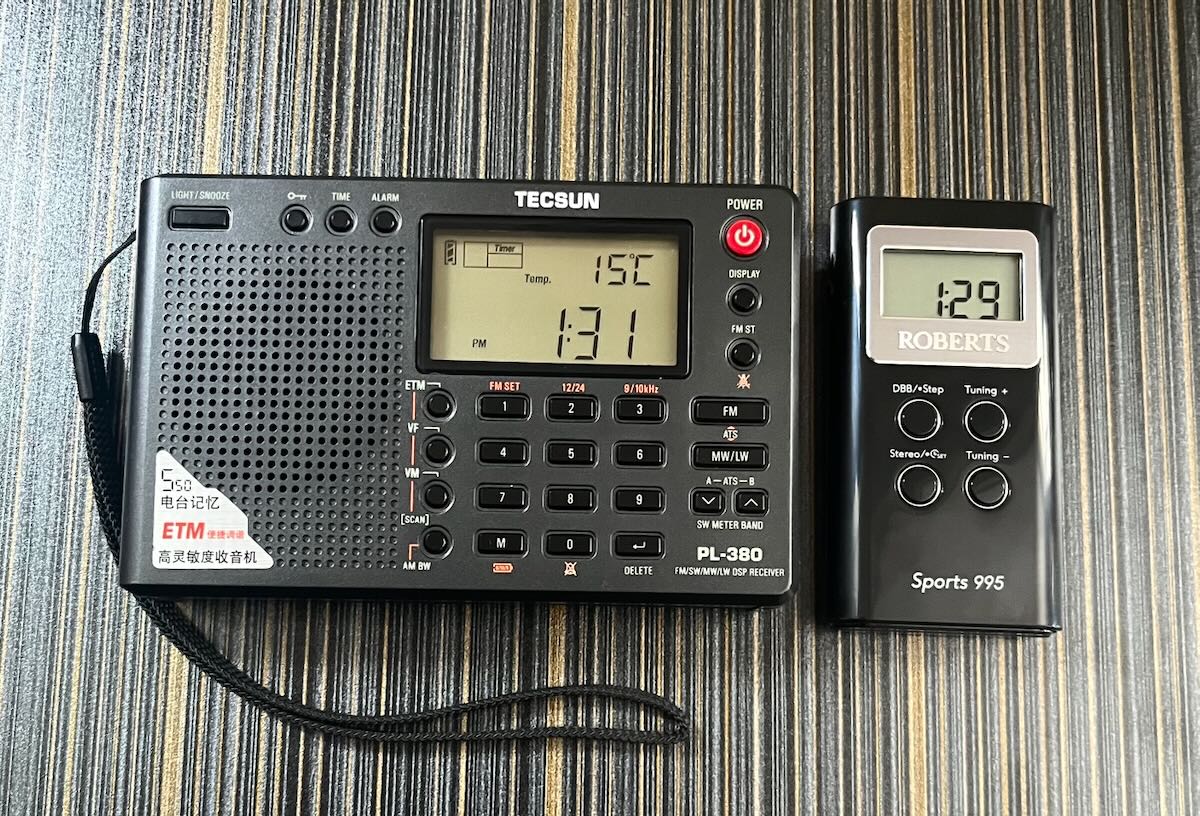
Both radios are of ‘ultralight’ status, but note the size difference.
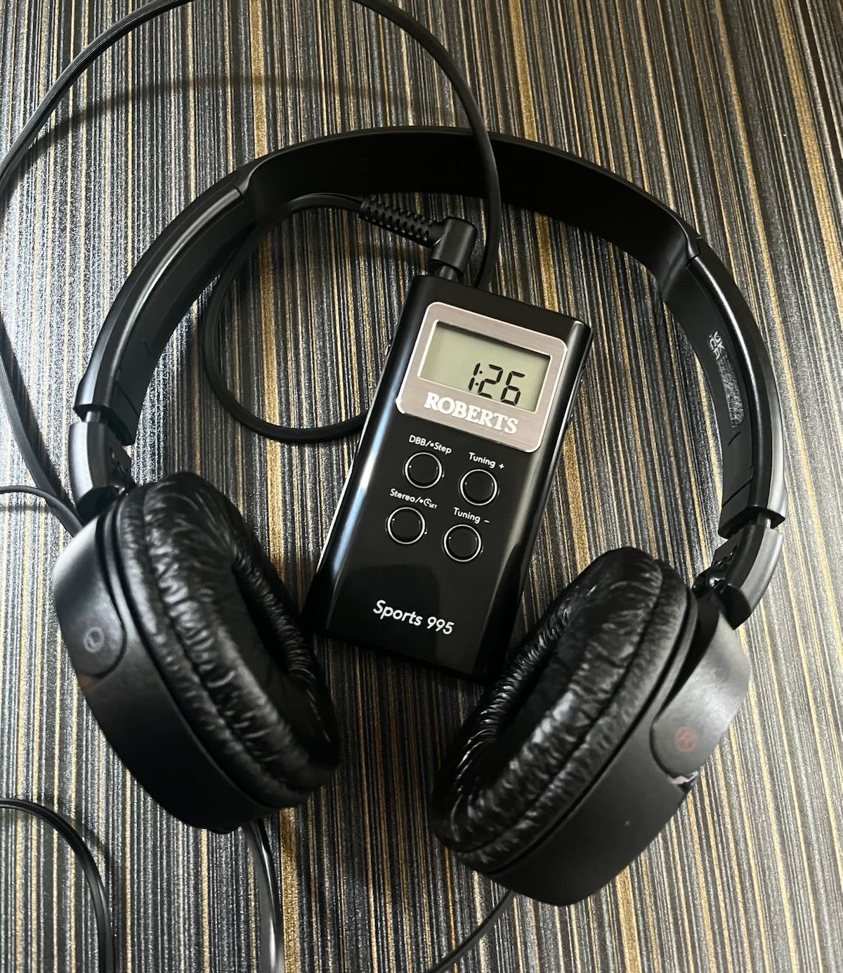
A couple of days ago, the mail arrived and with it, brought another ‘shirt pocket’ radio for my ever-growing collection – a Roberts Sports 995, which I believe to be a rebadged Sangean DT-120 for the UK market.
Two AAA batteries brought it to life, and a quick glance at the manual told me how to set the clock. I plugged in my headphones and confirmed all was working before waiting patiently for the dark hours to arrive.
I live in a rural location just outside of Edinburgh, Scotland and my band scan was done indoors ‘barefoot’ – with no passive MW loops or suchlike, anywhere in sight.
I settled in with the new radio around 12:30 am and began to scan the medium wave frequencies.
I have omitted the strong daytime stations from this list. Here are my results;
648 kHz – Radio Caroline, Orford Ness, Suffolk, 4kW
327 miles
882kHz – BBC Radio Wales, Washford, Somerset, 10kW
324 miles
972kHz – Sunrise Radio, Southall, London, 1.6kW
323 miles
999kHz – Cadena COPE, Madrid, Spain, 50kW
1067 miles
1035kHz – Lyca Gold, Southall, London, 2.5kW
323 miles
1116kHz – BBC Radio Derby, Burnaston Lane, Derby, 1kW
217 miles
1170kHz – unable to ID foreign station
1260kHz – unable to ID foreign station
1296kHz – Radio XL, Birmingham, 10kW
239 miles
1305kHz – Premier Christian Radio, Chingford, London, 0.5kW
322 miles
1368kHz – Manx Radio, Foxdale, Isle of Man, 20kW
129 miles
1386kHz – Radio Baltic Waves International, Viesintos, Lithuania, 75kW
1093 miles
1458kHz – BBC Asian Network, Birmingham, 5kW
239 miles
1467 kHz – TWR Europe, Roumoules, France, 1000 kW
930 miles
1557kHz – Radio Letna, Kaunas, Lithuania, 50kW
1064 miles
1602kHz – unable to ID foreign station
I am fortunate enough to own a number of this style of radio, and this is without doubt the best performance I’ve experienced with one of these. The Roberts Sports 995 truly is, in my opinion, a tiny DX machine, which will only improve further with an MW loop. I know of no better performing “super ultralight” in this price category (RRP £39.99). It is well worth considering if you happen to enjoy this area of the radio hobby as much as I do.
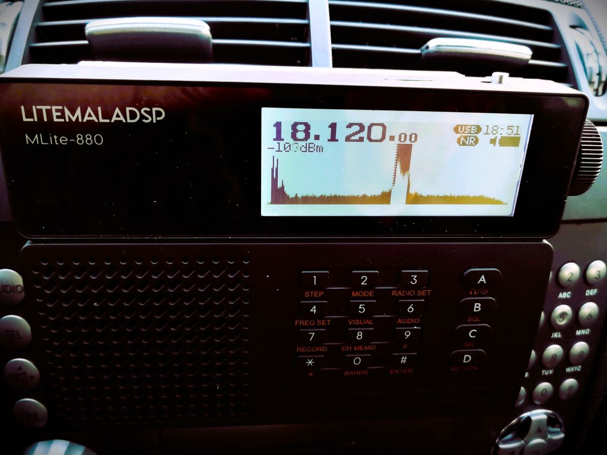
Following up on the article I recently wrote about the MLite-880, I still had a comparison with a reference radio on a proper antenna on my to-do list. I wasn’t in a hurry because I got pretty fascinated with exploring what I can get out of various magmounts on my car with this radio, which is quite a lot and it never gave me the feeling of missing out on something. I was also a bit hung up on the idea of comparing the MLite with the Belka because, you know, same price level and all, but that’s a bit iffy with my little passive splitter and 2 different input impedances.
Then a claim was made on the interwebz that the MLite-880 would be just a mediocre radio that would not stand scrutiny without its outstanding noise reduction, to summarize that in my own words. My experience is obviously very different and it made me curious how much truth could be in this claim. So I just took the ingenious Icom and the mediocre MLite to the dike to slip in a little shootout and then maybe give the loser a Viking funeral on a little raft I improvised out of flotsam and jetsam while making a lot of recordings to give my findings a whiff of evidence.
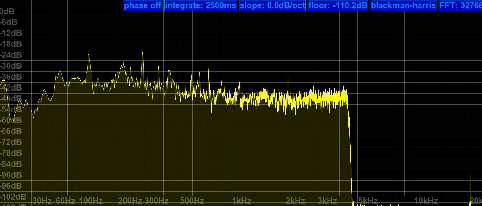
Both radios were connected to my lazy 10m/33′ monopole antenna via a Diamond SS-500 splitter and 15m double-shielded and common-mode choked coax. Both were recording to their own SD cards, but unfortunately, the recorded audio from the Icom does not represent the live audio off the radio on AM recordings because it records to an SD card with an 8 kHz sample rate, and that limits the audio bandwidth to at best 4 kHz. The deciding thing to listen to in these recordings is the noise and sometimes the pure existence of a signal, though, and lower bandwidth is almost an advantage in this context.
oznorWO
Sensitivity Test
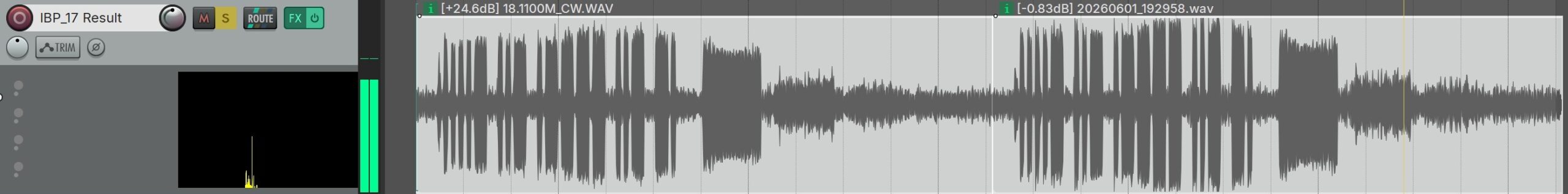
Since the question is really the practical sensitivity and, therefore, how dependent this radio is on its noise reduction to get good results, I’ll start with the IBP beacons, which were recorded without NR, of course. To spot and quantify SNR/sensitivity differences you can use the four -10dB stepped (100W, 10W, 1W, 0.1W) dashes the IBP beacons transmit after their callsign.
The most grassrootsy first: OA4B in Peru (10,800km/6,700mi) on the 17m-band. MLite first, then the Icom. Both radios receive the second (10W) dash as faintly as the 100W dash, but with too little SNR left.
5Z4B beacon in Nairobi, Kenya (6,600km/4,100mi with a 3rd dash = 1W!) informing a silent 15m band about the opportunity around sunset. MLite starts again, then the Icom. The latter has the 3rd dash faintly but clearly and the former leaves some more ambiguity about that. Demonstrates again the minuscule difference.
5Z4B again, but on 20m with a 4th dash to count, whether or not the last one is really from 5Z4B or just interference doesn’t matter; what counts is that both radios heard it. The 1W dash was clearly received by both, starting with the MLite.
Here’s one where only the MLite heard an interference, and I’m not sure it imagined it (absolutely unavoidable pun) – VK6RBP in Australia for the 10,000 miles bragging rights.
I think the conclusion here is that we could probably agree on “same ballpark”, right? I don’t know about you, but imagine my surprised Pikachu face!
The AF SNR difference, which is probably all that counts in sensitivity tests, is within 3dB between the two, not to be confused with RF power decibels (but reflected on the RF side in comparably small amounts). For the interested:I did take day/night variations of the noise floor above 10MHz into consideration, with a decreased noise level around midnight on 21MHz, the MLite still matches the Icom, which is all that counts in this comparison (not absolute measurements) context.
The magic button
Another claim was made about the noise reduction, that it would only work with signals of a certain strength. While it is technically correct that it needs a minimum SNR to improve upon, my experience is that it is effective with almost any remaining SNR, provided the signal is fed into the NR with sufficient levels, and it exceeds all my expectations at that. Here are a few recordings of CHU demonstrating both points:
CHU 14670 kHz in Ottawa (5,800km/3,600mi) in bad enough conditions. The same announcement from the IC-705, then the MLite with NR at ? of its range. Note how difficult the French announcement at the end of the transmission is for both radios. I will miss that station. The noise, not so much.
This is just the announcement a minute earlier, when the signal dipped below the noise floor. Nothing gets really recovered, but nothing gets lost either, and what’s left stands out more:
However, if you only look at its inability to cheat physics, you could be missing the point of a good noise reduction in this particular “shortwave radio” context. Restoring fidelity, removing masking noises and generally increasing the SNR and thus ease of listening is having a massive impact on how at least I can enjoy programs or conversations and there’s more: After a few decades many of us (particularly 2-way) radioheads have gotten their auditory cortices hardwired to make a connection between noise and signal strength and then pushing this NR button might feel like witchcraft when it makes a bloke driving around on the other side of the globe sound like he’s just passing your local highway intersection.
In the following sound clips you will hear both radios taking turns in 5-second chunks as if I switch forth and back between them, in some of them I will play the same bit of transmission twice, first from the one, then the other radio so you can e.g. make out differences quite precisely. Continue reading →
After all the recent buzz and watching and reading every video, review, and discussion thread/group I could find about this radio, as per usual, I knew I had to buy one in order to find out if I want one…again. This is not a review, but taking notes while getting acquainted with it and gathering the technical information I couldn’t find, I started thinking that sharing this might be at least entertaining for other MLite owners, maybe helpful to elaborate on a few things for newcomers to complex radios and SDRs on the way and also to tell the undecided why I started calling it names so I had to keep it. Sounds terrible and very much like a review, so let’s get on with it.
Chapter One: What is this thing anyway?
I couldn’t help noticing the higher-than-usual pile-up of “game changer”, “new era,” or “the radio <brand name> never made” expressions coming with this one, and I was confused. Sure, it is another small, self-contained SDR, functionally more or less just a mildly simplified Malahit redesign with a much simpler display in a more familiar shape, but the Malahits have been around for years, and they’re neither the first nor the only radios with this job description. I couldn’t quite understand what fueled the sudden interest, just because it doesn’t look like Spock’s preschool tricorder and more like the offspring of an Asian travel radio and a Scandinavian business phone? Really? Then I found the price tag and the light came on.
That it’s now also much easier to purchase the new Gründig Sputnik 880 as an official product with authorized firmware from Malahiteam’s new Chinese manufacturer obviously did it for me too, and it may speak even more to people who have really been waiting for an affordable, actual step-up from their first 473x-chip radio for so long that they bought 5 more of those in the meantime. I promise it may be quite an upgrade from any radio that looks similar, and I even deem it pretty user-friendly. However, it’s technically and conceptually still a Malahit and as such much closer to any other SDR hard- and software made to cater to the exotic desires some outspoken radio enthusiasts have, than to anything it is made to look like.
Unfortunately, this is really clashing with very frugal documentation and unusual technical secretiveness about what’s in there; people have to figure out many things on their own and fail at it, and I feel the mimicry is also fueling unrealistic expectations.
Chapter Two: Technical Notes
The “technical secretiveness” extends to filing the markings off most chips, so little is known about the innards of this receiver. Russian YouTuber Alexey Igonin suspects a single-conversion SDR on shortwave (up to 27 MHz) becoming a dual-conversion radio above. The FM broadcast range appears to be a separate tuner active between 65 and 107.999 MHz and another VHF tuner from 108-165 MHz; both tuners are then downconverted to the high IF of the SW receiver. This abstract string of words explains to the initiated why oddities may be seen here and there, for example, when you tune to 108.00MHz
Operating concept
For a general description of the radio, menus, and general operation of the MLite, please refer to Dan Robinson’s and all the other excellent reviews. I want to sell you on the general concept centered around the telephone keypad, making it strangely not such a big deal for me that it has only one encoder knob and 16 buttons. It’s quite different from all button portables I have met:
Each function menu has its own button, assigned to 9 of the 12 buttons on the phone keypad. Each function in these menus has a number, too. That means you can memorize access to your frequently used functions by a 2-digit number, one for the menu, the other for the item you want, and in many cases, that’s all. Dial 25 for AM, 26 for SAM, 21 for USB without further action, 61 is the number of the IF filter warehouse expecting your orders via the knob (unless it isn’t), you get the idea. That means most functions on this radio have 2 buttons you need to tap, but they all have their own 2 buttons right on the front panel.
Direct frequency input is activated by button [4] and is accepting a couple of ways to enter a frequency followed by button [A] for kHz and [B] if you want MHz, e.g. “123*125 [B]” or “123125 [A]” take you to the same frequency, or just hit “123 [B]” to go to 123 MHz and tune up a little. Some even recent radios are much less tolerant and made me give up on typing in frequencies; this is not one of those.
Such an anachronistic flashback to early digitally controlled commercial radios/machines/things or DOS computers seems to be almost ironic on the face of this bundle of latest digital wonders. But I think it could easily run circles around nested menus on a tiny touchscreen if you can adapt to it. The keys are not backlit but if you could dial 911 in the dark on an old landline telephone like the victim in an old crime show episode, you can position your fingers on the keypad to type “4-27555-A-21” (hyphens for clarity, it’s actually 42755A21), if you have firmware 1.5 or higher this will take you to the CB “highbander” calling channel in USB, hopefully entertaining you until the ambulance arrives.
Unfortunately, there are also multi-page menus like the [AUDIO] page with your filters, so “61” doesn’t always work, and e.g., the steps menu changes its buttons according to the mode, so the “mental phonebook” method becomes a little more involved. Still, when you exit and return to a menu it will still have that previously selected function assigned to the encoder to speed up things and it memorizes that for each menu individually, long press of the SQL [B] or NR [C] button (while they’re on!) takes you directly to their intensity setting in the menu…in short, things have been laid out very well and after a few days that became part of the fun this radio is. Summary: It’s a real asset because it allows you to fly this radio blind, for example, when you’re legally blind or just legally supposed to have your eyes on the road.
Antenna Input, Impedance Switch, and Bias-T:
An understandable common misconception seems to be that the antenna switch [3][1] is toggling between the whip and the 1/8″ phone-type antenna jack. What actually happens when you insert a phone plug is that the whip is getting disconnected, and the switch is toggling between high and low input impedance. It seems rather important to understand that this high impedance input is provided by the additional amplifier needed for the whip; it remains in the signal path when you use the antenna jack.
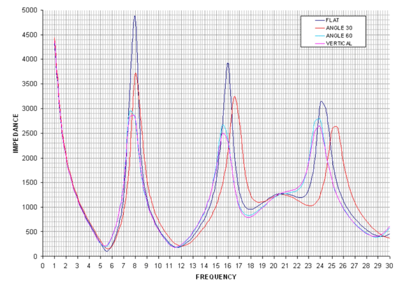
In general, switching impedance allows for external antenna configurations that would otherwise not work well, and in the presence of high local noise levels, the shielded input is highly preferable over open wires alligator-clipped to the whip in lieu of a missing Hi-Z input. Besides matching different antenna types, switching impedance can also increase the number of “good” frequency bands on the same (passive) antenna. Most antennas, including simple passive wire antennas like endfeds etc. exhibit a wild up and down of impedances over the wide range of wavelengths we SWLs use them on. When the impedance mismatch happens to be at its most loss-inducing extremes in the band of our choice, switching the input impedance may or may not improve reception:
VK6YSF’s impedance vs. frequency plot for an endfed antenna in different orientations
For example, a simple magmount whip on the car roof is often all you’d need for a bit of quality mobile SWLing, but impedance mismatches between the external whip, the cable, and the input can suck the life out of it on many frequencies. My “Little Wil” CB magmount doesn’t work well on 20m…switching to Hi-Z can fix this. In other bands, this will not improve anything, and the MLite is kind of giving a clue on this bad constellation by becoming very noisy when you switch to Hi-Z in these cases.
The additional amplifier helps with these small, lossy antennas, but that advantage can turn into the opposite when it gets overloaded by “full-size” antennas, and the simple logic “Hi-Z antenna works best on Hi-Z input” doesn’t always work anymore. Leaving this for everyone to figure out on their own is provoking bad results and bad rep.
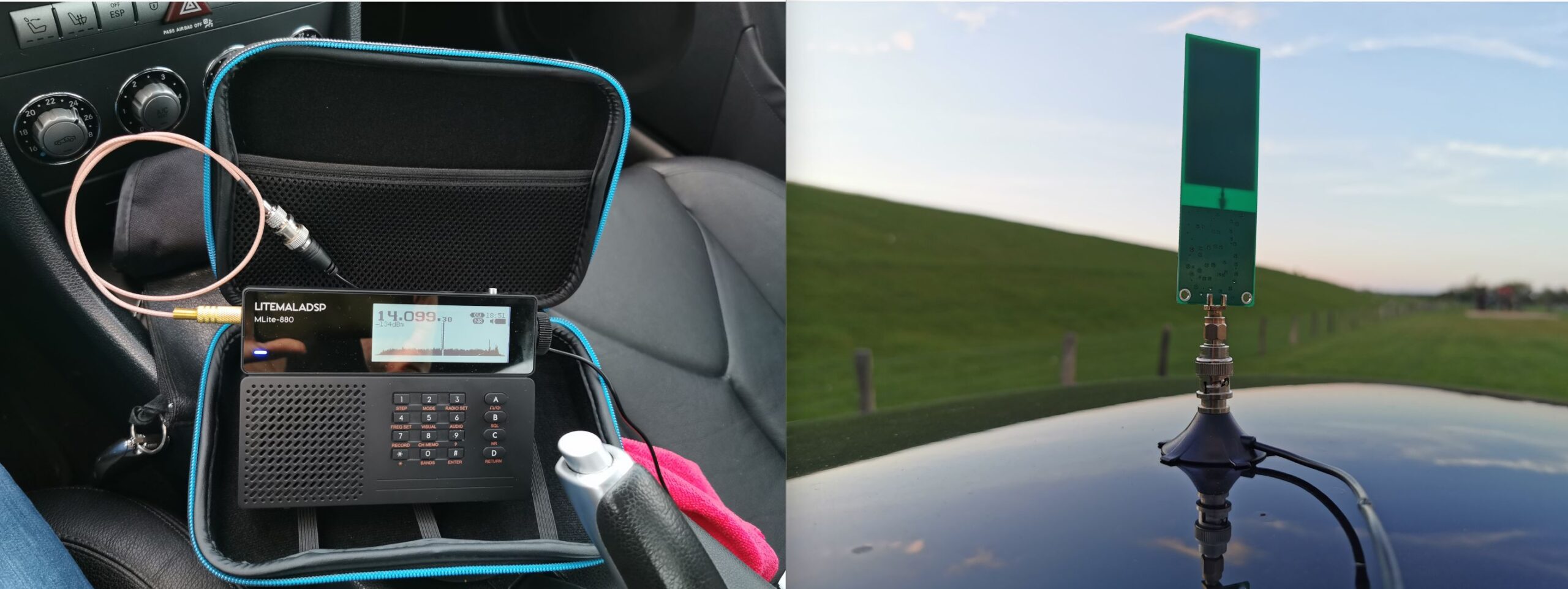
This radio offers to pass the (unregulated, drops during discharge!) battery voltage to the antenna jack for active antennas and LNAs at no extra fees. I could finally try if a tiny miniwhip could be a worthwhile low-profile solution for the car roof, one that gets enough shortwave in while keeping the considerable electromagnetic racket within the car out. Turns out the 15 bucks drawer-queen miniwhip PCB that was once powered up for 10 seconds 10 years ago seems to be pretty happy with sitting on a car roof, it works almost as well as a 47″/1.20m telescopic whip while theoretically giving a very low profile, avoiding the RC-car looks. Too bad nobody makes an autobahn speed compatible, magmount miniwhip for cars, hint, hint, nudge, nudge.
Spectrum Display
If the Panicsonic RF-KGB-65 is your first radio with a spectrum display, welcome or welcome back to the world of radios that have something nice to look at. I appreciate the feature too, and maybe it’s a good thing that it doesn’t overwhelm people with information, but a spectrum graph line without scale/grid to tell how wide, far apart and strong signals are on that spectrum does not provide very much information beyond revealing the pure existence of something left and right of your tuned frequency. Still a great thing to have and a mesmerizing and instructive eye catcher and only a white cat can make you look more like someone out of a James Bond movie while consuming almost no battery.
How much of the spectrum you can see depends: What you actually get anywhere on AM/SW/VHF is a 40 kHz portion of the band, and you can’t zoom in or out, likely because that’s how much you can reasonably expect to show on a low-resolution dot-matrix display, expecting narrowband signals on the band. Narrow signals are also why the spectrum line should be filled, or unmodulated carriers/CW will be represented by a single, hard-to-see dot instead of a full single line. In WFM we get roughly 600kHz of spectrum from that display, which is just the FM equivalent of “not an awful lot”. On the plus side, you almost never have to bother with spectrum settings (which can be a rabbit hole, trust me).
Averaging means that the height of each dot in the spectrum line is calculated off more samples, the more samples, the longer they live on the display, too. This allows the display (and us) to differentiate between weak signals and noise. I found the most useful averaging settings in the upper half of the range 50-99, not quite as good as a waterfall display (= a history of spectrum plots), but ’99’ will allow you to blink very slowly and not miss an activity, at the cost of display responsiveness. Too little averaging also makes you miss fast events on the “bandscope” even when they’re loud.
To alleviate you from more settings, the radio is automatically scaling the levels of the spectrum line. If a strong station comes up within the spectrum passband (not necessarily within the 40 kHz display range), the scaling changes and the visual noise floor drops. This looks confusingly the same as if the AGC was “pumping” and radio would be actually desensitized by that station. This can actually happen, but then you will also clearly hear the AGC “pumping” the noise floor as the display seems to indicate. That scaling also means that the visual noise floor does not reflect the actual level or proportion of the noise floor; deriving SNR differences from the graphical representation is not always possible.
Both spectrum and signal meter displays seem to indicate frontend input levels pre-AGC; changing the gain in the radio does not affect the display (the built-in attenuator does, of course). Besides the spectrum, the display has the usual status indicators but the very limited display space may not allow for all indicators people could wish for. The bargraph signal meter can be switched to an alphanumeric dBm display aligned with the classic S-meter 6 dB/step scale (not dB/?V) as indicated by the meter refusing to measure signals beyond -73dBm (S9), in which case it just notifies you of the surplus level by adding a ‘greater than’ sign to the value, “>-73dBm”. Still, the numerical measurement is pretty averaged/integrated and therefore nicely readable below that. Which is good because the meter does indicate the noise floor.
Controlling Gain, AGC, and ATT:
Most of the radios the MLite-880 is cosplaying have an AGC that doesn’t require any interaction and many of them just have a “one size fits nobody” response curve for AM and SSB. Likewise, most portables don’t have gain control beyond a “Local/DX” switch on the side. The MLite AGC, on the other hand, offers 4 release speeds with variable ‘Gain’ and ‘Limit’ parameters, plus a manual gain control option.
Of course, I’m pulling this out of the nose since it’s all not documented, based on my observations and similar arrangements: In very simple words, ‘Limit’ sets how loud you want the loudest stations to be, and ‘Gain’ is how loud you need to have the weakest station, particularly in SSB.
To elaborate on that, ‘Limit’ sets the threshold level where a signal causes gain reduction, and ‘Gain’ is basically the “RF gain” control some people think is missing on this radio, giving remarkable gain reserves (60dB). Use ‘Gain’ to bring weak stations closer to the ‘Limit’ threshold. “Limit” defaults to “75dB” and it looks like signals around S9 are going to be, well, limited to that, which means raising that is lowering the overall AGC action as much as decreasing gain while it increases the volume. The closer these two values get to each other, the more compressed, noisy, and “pumping” the channel will sound. Keep in mind that gain does not equal sensitivity, and avoiding AGC action is often preferable over the convenience of not needing to touch the volume knob. Matching gain to the conditions and signal you want to receive is also a prerequisite to make the most out of the noise reduction. This old clip demonstrates the difference it can make when you can control gain to avoid getting loud signals squeezed by AGC and the noise floor not being pulled up unnecessarily (same transmission received on a D-808 (no gain control) vs. a Belka (has gain control), recorded simultaneously):
A sound like this is the sign that you may want to reduce ‘Gain’, or use the attenuator (dial “33”) to that effect.
I’m not sure I understand or experience all of the issues some seem to have with the AGC; other than that, it does not default to the hottest gain settings it is capable of, which adds to a different problem with this radio – the harsh drop in volume in SSB/CW and WFM modes compared to AM/SAM/NFM. That also might be pushing people towards increasing gain beyond reasonable values to compensate.
The ATT can be set to 36dB of attenuation in 6 dB-steps, but for some reason, I can see at best 15dB of it on signals anywhere on the S-meter scale, high or low, which seems as strange as the fact that it didn’t help in the only overload situation I had with this radio. If this is your first ATTenuator, it’s supposed to decrease the signal in front of all amplifier stages, unlike most RF gain controls, it is often the radio’s only reliable (onboard) way of keeping the radio’s first transistors from overloading in the presence of very strong signals. Please note that it says “Attenuator for SW” for a reason: It does not work on VHF, which in this radio seems to start circuit-wise on 27.000 MHz so the 10m-band has to make do without.
Noise Blanker
Unlike most portables, this one has a noise blanker, and of course, it’s not only an on/off switch like in the old days. Invented 100 years ago to mitigate engine ignition impulses, nowadays they can be used to mitigate impulses from electric fences, OTH radar, or local PLC modem (!) impulses, which is why you can often adapt the timing parameters. Of course, this one is hurtfully undocumented again, I assume that the 3 modes of the NB relate to bandwidth presets. The other dimensionless control seems to set the timing of the countermeasure, but it always seems to work best or at all at the minimum value. Since I assume this radio attracts many buyers unfamiliar with these things, be advised that wrong and even the default settings in modes 1 and 3 can cause distortion in the demodulation when you don’t expect it, so it’s better not to leave that permanently on.
Here’s a short video showing how it works on a strong OTH radar, the noise blanker is acting in/before the IF stage so its effect also reflects in the spectrum display:
IF filters:
A big giveaway that the 880 is not to be confused with a radio is that it visually alludes to are “the filters”. Of course, in SDR, there are no physical IF filters and barely any limits to their number, shape, or properties, and it shows:
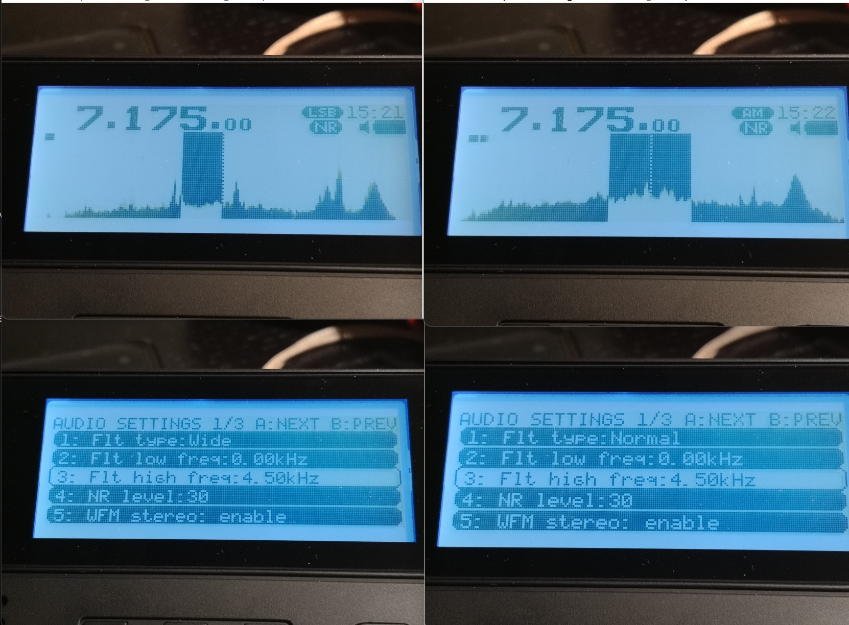
The [AUDIO] menu has 3 slots for your own filter settings named “narrow”, “normal” and “wide” and in each you can define low and a high cutoff frequencies, so that’s 3 variable filters so far. But of course, each mode has its own set of 3 “filters” you can define to your liking. The MLite-880 is one-upping this by giving AM and SAM, USB and LSB each an individual set of 3, too. WFM has 4, that’s 22 (!) places to set filter bandwidth. That’s not mandatory, of course, but still one nice source of confusion for elderly people like me and something to keep an eye on for a while.
The filter shape itself is fixed, it has less rounded shoulders than what I have in the Belka and the IC-705 in “sharp” mode, with the same quality and perceived stopband rejection of those, and that alone would be enough to lift the long-term reception experience with the MLite way above and beyond the 473x chip radios, or even the best of their small analog ancestors from Japan.
Nice upper filter slope (lower filter frequency = 0) to claim all of a 9kHz ITU region 1 mediumwave channel and still keep the neighbors out.
25m band scan on a 10m vertical at the dike. It also demonstrates that the 4.5 kHz filter setting shown above is keeping the signals 10 kHz to each side of NHK on 11,625 kHz in check (NHK also received on 11,860 kHz, both direct from Yamata).
As for the mildly important question, what bandwidth is meant when you set the filters in AM – this is once again “per sideband” in AM, like on the Tecsuns: 4.5 kHz means 4.5 kHz audio bandwidth, the old-school physical IF ladder filter equivalent for that kind of passband would be labeled “9 kHz” if you want to compare that with some old rig. What sets this apart from e.g. my Icom is the possibility of having very wide sidebands up to 15 kHz for 30 kHz wide experimental AM broadcasts, also in SSB. The MLite reflects the IF filter equivalent in the width of the “dial pointer”:
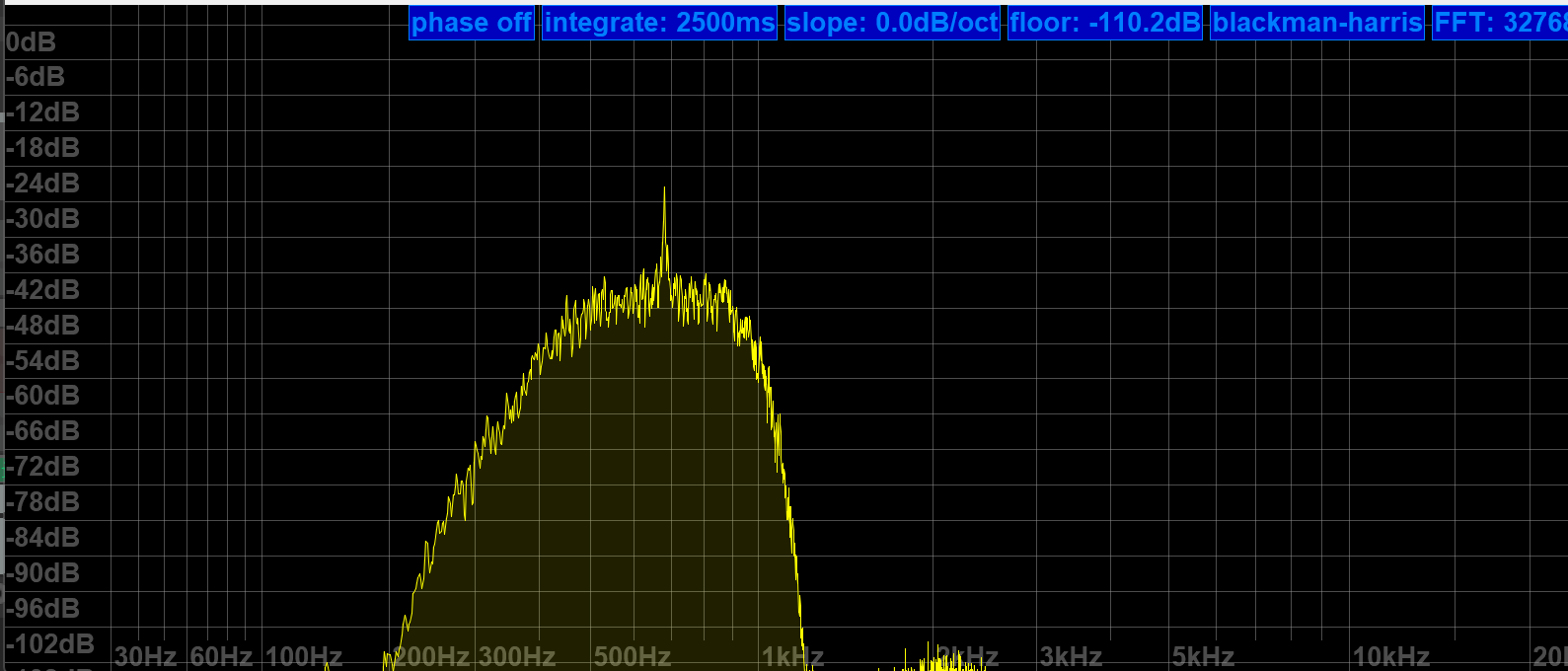
The properly narrow (>200Hz) and SNR-increasing CW filters are what make this ????? Trans-Okhotsk and the Belka the only receive-only portables with proper CW reception and a price tag around $200. Since FW 1.5, it also does CW “offset compensation”, so you don’t have to go through the hardships of subtracting your adjustable CW pitch frequency to correctly tune to a published frequency like in the Middle Ages anymore.
MLite 500Hz CW filter more or less centered at the CW signal at 700Hz
Frequency Calibration and Stability:
You can skip this section if you’re not much into SSB, and the following is not a complaint, just an observation and generally not a big deal, or rather part of the deal: The MLite-880 is not perfect <gasp> and it has “Lite” in the name for a reason:
Besides more obvious things, it lacks the automatic notch filter and the TCXO (temperature-compensated crystal oscillator) of the “big” Malahits. It has to make do with an XO and a lot of XOXO, and with that, it can’t quite match the linearity and temperature stability of the Belka, which is 99% on par with the IC-705. Most people are probably familiar with the need to calibrate their radios, and a few less have a radio that lets them do this, but not needing to do this is understandably one of the expectations people have with this SDR. But unlike the SW range, which is generally close enough to the nominal frequencies for most buyers, the separately calibrated VHF range seems to be in need of an initial calibration on many shipped radios; it was several kHz off in the VHF marine band on mine, too. I just tapped [3][5] and turned the knob until the station showed up right. Easy enough.
On shortwave, I’m talking about very small but occasionally inconvenient offsets/non-linearity in the tens of Hz range, nothing that makes you want to find your pocket calculator even if you’re a heavy SSB/utility listener. Calibration on digital receivers means you can fine-tune the master oscillator conveniently in a menu, and “non-linearity” means an offset varies over the course of the frequency range and does not plot a straight line. The offset is different in different bands, and you may or may not want to recalibrate there.
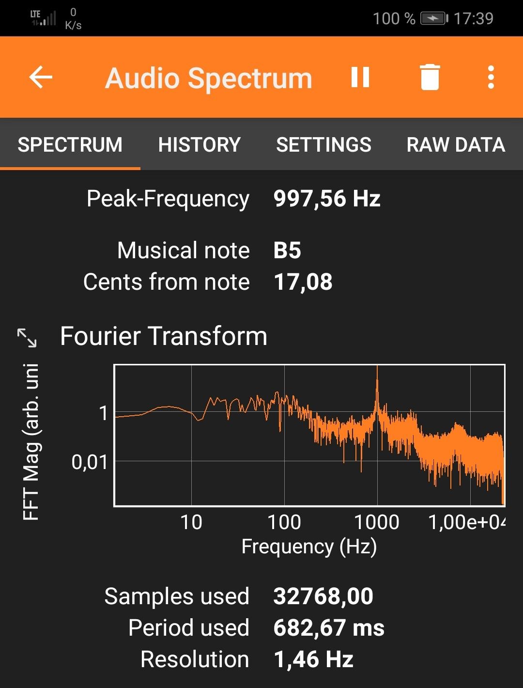
Calibration procedure (may not work on analog receivers!): Find a frequency standard station (like WWV, BPM, or RWM) or just a regular station with no (or a published) offset. Tune 1kHz lower than this frequency and switch to USB to create a 1kHz het. Put that in a memory slot. Tune 1kHz higher and switch to LSB to create a het again from the other side. Now get your cellphone with a free spectrum analyzer app like Spectroid or Phyphox on it so you can easily measure the frequency of the het: It should be close to 1kHz in both USB and LSB. Starting technically at 27.000 MHz, the VHF range has its own calibration setting when you go there and you ideally want to find a calibration station near the top end of the range, like a 2m repeater or something.
For example, the needed offset on 5 MHz is -5 on my radio, on 10 MHz it’s +64, and +72 on 15 MHz at a cozy 25°C. That means I can calibrate for a negligible deviation in the 10 and 15 MHz signals and live with a somewhat bigger offset on 5 MHz, or I can make them all within +/- 30 Hz off, which is still awesome by analog radio standards and not terrible for a modern radio, but requires fine-tuning when you need it better than that. Calculating the indicated vs. actual offsets it dawned on me that the unit used on the shortwave side is still “x0.1ppm” and the math doesn’t math, that should read “x0.5ppm” as well.
The best I can get without 5MHz being off too much – good enough!
On top of the general offset, there’s also a noticeable (at 10-15°C differential) temperature drift, making the calibration efforts less persistent outside than I’d wish for. +72 for 15MHz at home to 120×0.5ppm at 15MHz equals 24Hz of temperature drift, adding to whatever offset was there before, which can amount to “too much” and there seems to be some “ripple” in the deviation curve: Here’s a recording of CHU on 14,670 kHz somehow ending 80Hz off right after calibrating the radio on 15 MHz:
Again, not great but not terrible in the grand scheme of things because deviations below 100 Hz are only ever a factor in SSB, and it may even add to the odd charme of this radio that it is very analog and old school within a tolerable margin in this regard. But if you try ECSS reception with music, your ideal deviation is none and 10Hz at the end of “tolerable”.
Fixing the tuning emergencies when your fav song is playing and sounds terrible in SSB is done by dialing (think nine) [1][1], the useful number of the fine(st) tuning step in all modes, or just hit [3][5] and use the calibration function as “RIT” knob until it sounds right, and you will be good. It’s not a calibrated Rohdow & Shwartzkiy lab instrument, you can’t break anything, and it provides the needed fine resolution you’d need for true “zero-beating” but yes, it does feel very luxurious to switch to sideband when a $5 TCXO makes sure you can rely on the radio being spot-on in SSB when the station is, on any frequency, even in winter.
Synchronous Detector
…can’t be missing on a decent SW portable and this one seems to be a (non-selectable sideband) “PLL”-type detector and gives SDR-typical results: Remember that AM and SAM have individual filter settings so you want to make sure you match them when you compare that, but this detector is as unspectacular in a good way as it could be, it has super-solid lock and does absolutely nothing, zero, nada to the signal other than keeping the multipath distortion in check, which it seems to do very well.
31m band scan (antenna; car roof whip) with a brief demonstration of the sync detector at 0:16 seconds into the video. Note how the piano distorts when I turn it off again. Continue reading →
Many thanks to SWLing Post contributor Alfredo (EA4IMN), who writes:
Hi Thomas,
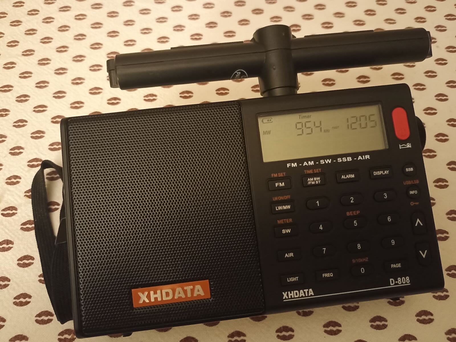
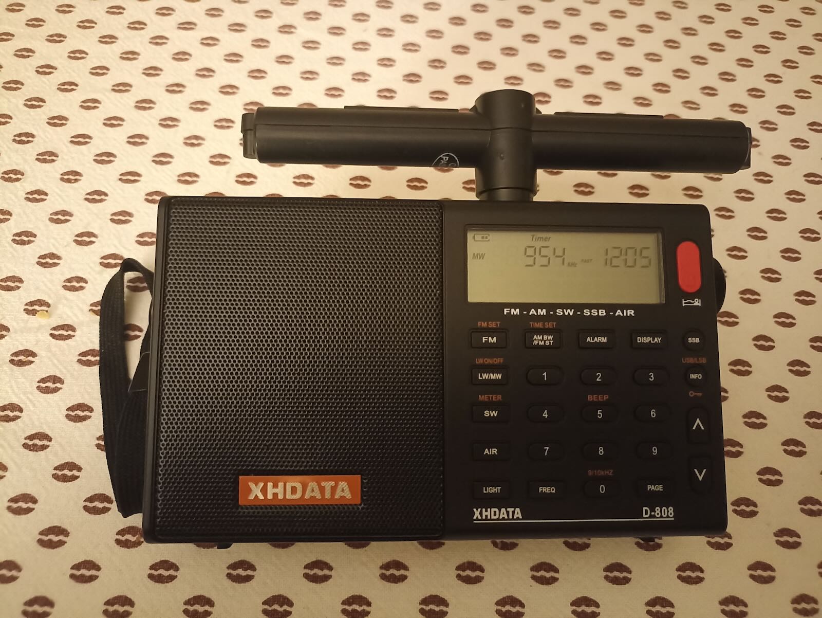
Greetings from EA4IMN. I recently purchased an XHDATA D-808, and got puzzled by the absence of an external jack for the LW/MW antenna. Inspired by previous work, I set to add this feature to my unit.
My journey was overall straightforward, but not without some hacking required, so I’m sharing my experience here, in case it helps others. (I have briefly documented this on another forum, but here you are the abridged version of the story.)
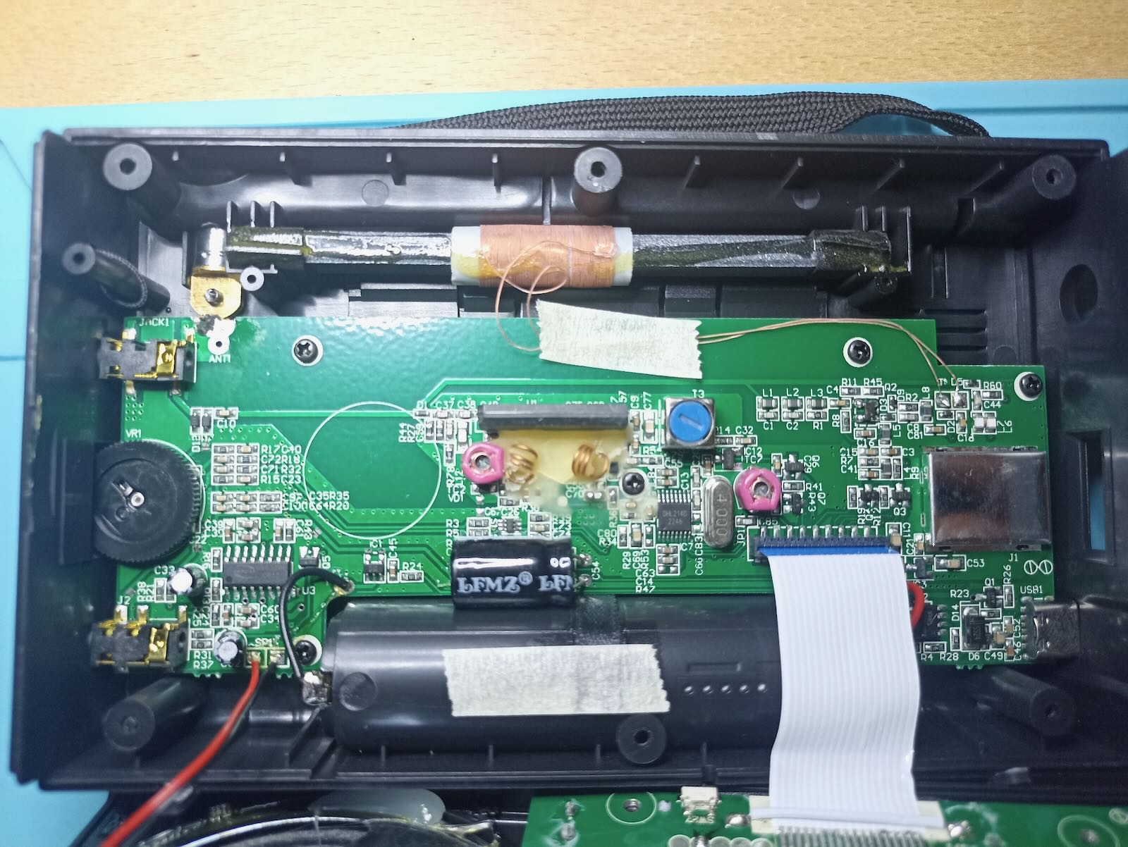
First, let’s start with a pic of the pristine PCB:
It’s a recent unit, and I observe it has minor differences even from some USB-C variants I could find on YouTube. I assume XHDATA keeps tweaking the inner design, and that’s not documented.
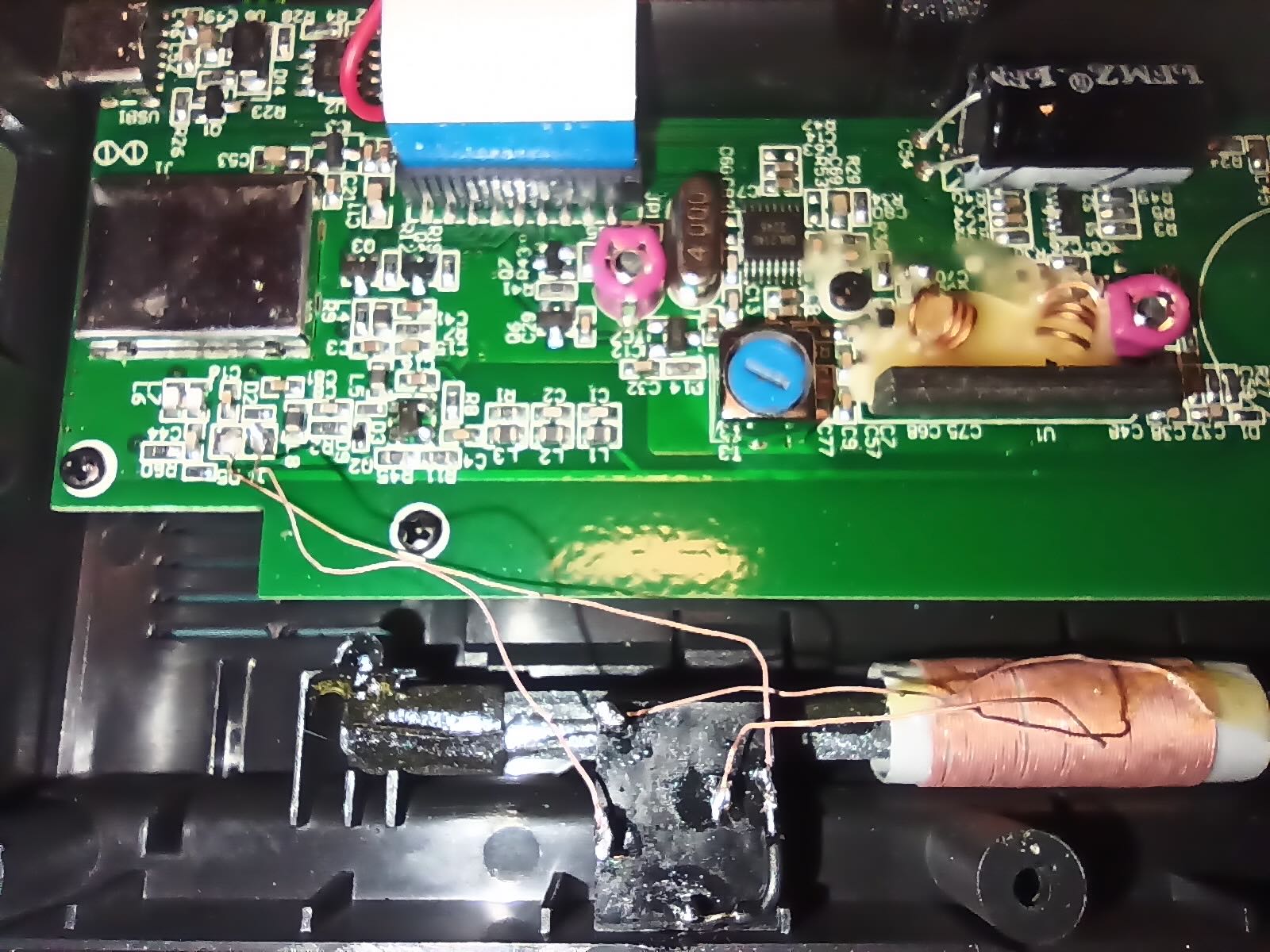
In the “external MW Jack” picture [above], you can see how I added a 5-pin female jack. Interestingly, I could entirely reuse the litz wires that came with the internal ferrite antenna. It works as follows:
When no male jack is inserted, the internal ferrite antenna is directly connected to the antenna pads on the PCB.
When a male jack is inserted, the internal ferrite antenna gets disconnected, and the PCB pads take the signal from the external antenna connected to the male jack.
Since I wanted to be able to also connect a long-wire, it was crucial to correctly identify the “hot” pad on the PCB, so that it would be wired to the tip of the jack (and not to the sleeve). It turns out that, on my unit, the squared pad was connected to GND.
I recommend anyone wishing to do this mod to verify the pad layout on their unit, since the PCBs keep changing. This is how to do it:
Pick one litz wire of the internal ferrite antenna and cut it. Make sure to cut it at a point that will later allow you to solder both ends to any of the 5 pins of the jack (you still don’t know if you cut the hot or GND wire!)
With a multimeter, check for continuity between the antenna pads and a well-known GND pin. In my unit, I used the audio amplifier chip, the CS8573E, for which datasheets are available, to check which pins go to GND. (Note: I first tried to check continuity with the negative pole of the battery, but that didn’t work, likely due to the battery recharge circuitry.)
Also, I recommend soldering the sleeve and ring pins (you can see a black wire in my picture): some ferrite antennas come with a stereo jack where the ring is floating, so the added wire makes sure all jacks are treated as mono, by shorting ring and sleeve.
Now… closing the unit was an issue: the 5-pin jack I just added clashed with the display! I had to get creative in a few ways:
Bend three pins in the jack that were clashing against the display. That made them just lower enough that I could “gently push” the case so that it would close.
Yet, the pins were now touching the metal cover of the display, hence shorting together, and nullifying the antenna! That was sorted by covering the metal plate with insulating tape. I had to add a couple of layers, since the soldered pins had rough edges that would keep piercing into the tape…
In the end, it all looked good to me, as depicted in the “Final result” photo:
Admittedly, the external ferrite antenna in the picture performs roughly the same as the internal one. But at this point, it’s just a matter of plugging another jack and keep experimenting!
More of Don’s traveling DX stories can be found in his book Tales of a Vagabond DXer[SWLing Post affiliate link]. If you’ve already read his book and enjoyed it, do Don a favor and leave a review on Amazon.
I’m spending April and May wandering around northern Spain and northern Portugal. My goal is to visit places I haven’t been to before, but I also have to return to Salamanca. I had been there twice before, but Salamanca is the kind of place that draws a person back. I love to wander the back streets of the old city. I also wanted to find some things I hadn’t done before, and that’s how I came across the Museo del Comercio (Commerce Museum) in a modern neighborhood east of downtown. That may not sound very interesting, but I knew immediately that I would have to go. One of the two main permanent exhibits is a collection of old radios.
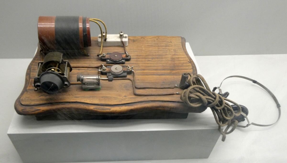
Most of the items on display came from the collection of Agustín De Castro. Agustín was born in Salamanca in 1928 and began building radios when he was eight years old. Here’s one of his early radios.
As a young man, he went into electronics and eventually operated his own radio store and radio repair business in Salamanca. He donated his vast collection to the city in 2002, and in 2006, it became part of the new Museo del Comercio, which was opened in Salamanca’s old underground brick water cistern.
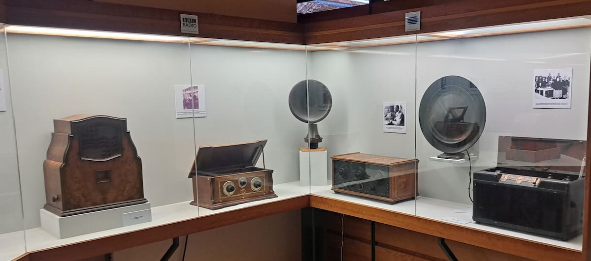
I might only DX on modern SDRs these days, but I still love looking at old radios. Everything here is in excellent condition and is kept in glass display cases to keep it that way. Unfortunately, that does make it harder to get good photos without getting glare or reflections. But I think these came out pretty well.
Let’s start with a closer look at a few of the more usual pieces.
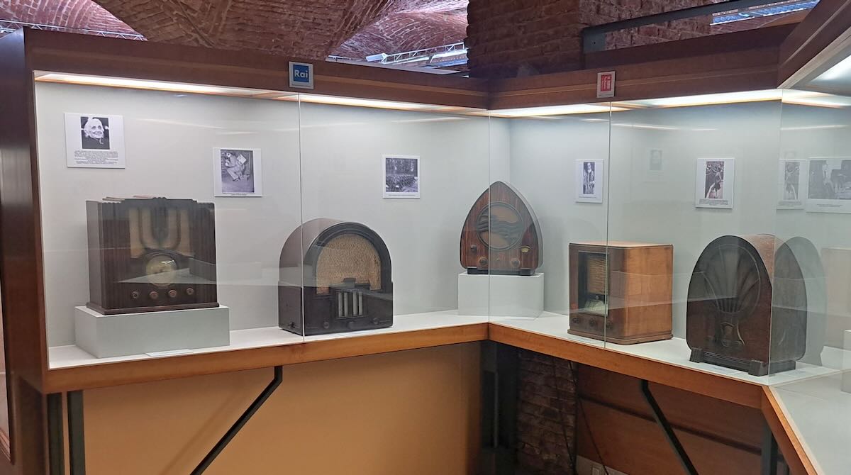
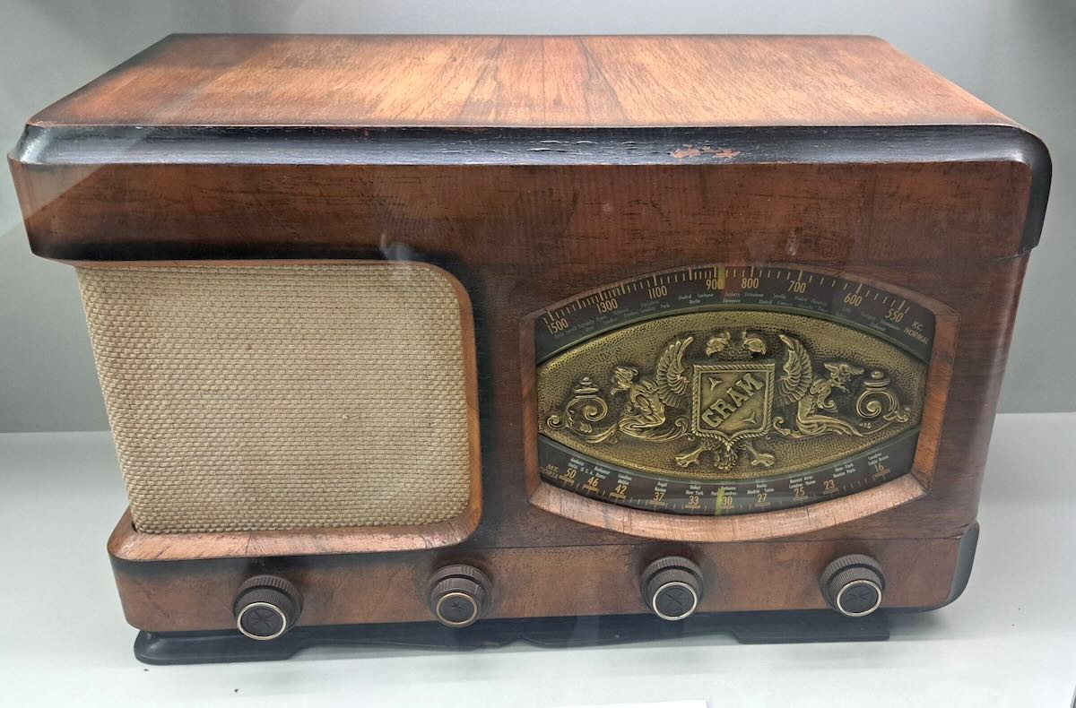
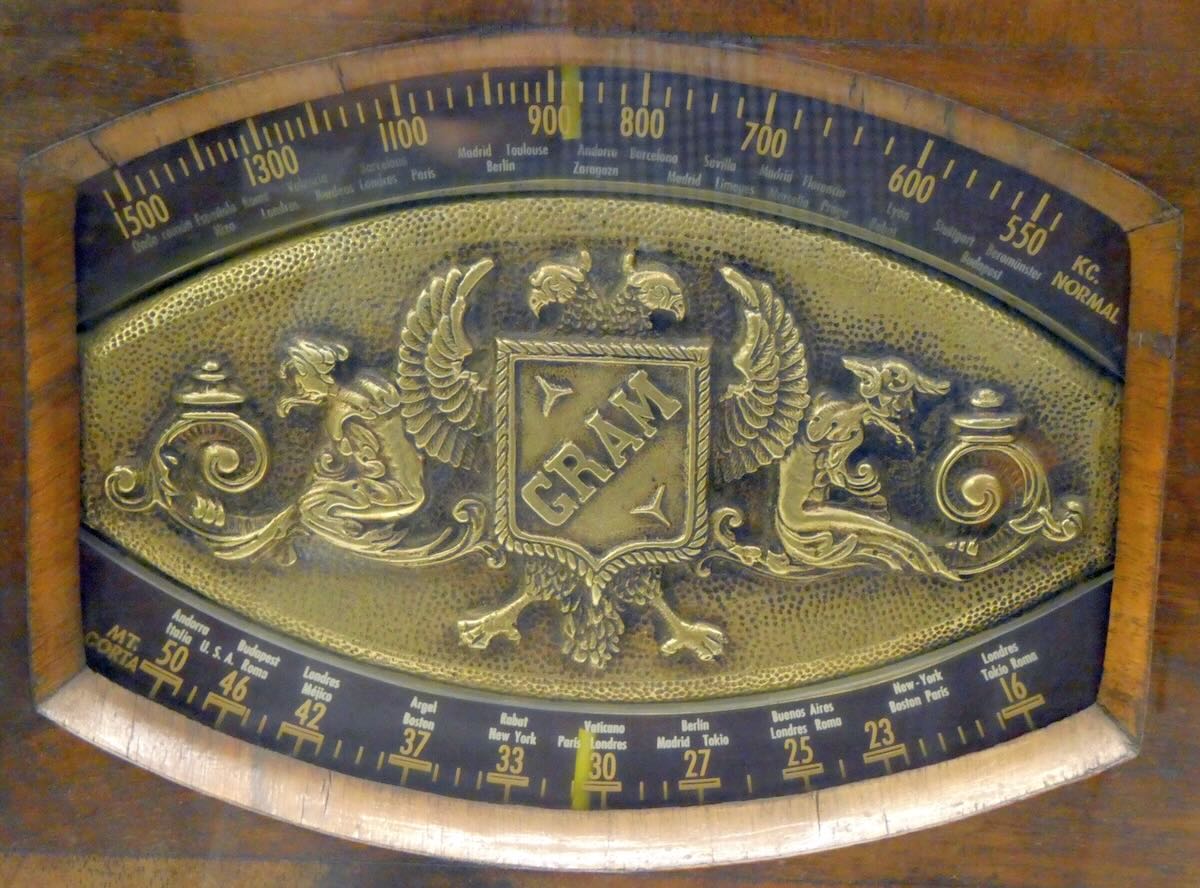
The Gram Model 157 was built in Spain in 1947. I liked this one for the fancy logo on the dial. Note that while the medium wave band at the top is marked in kilocycles, the shortwave band at the bottom still used meters.
The Fono model 140 was also made in Spain in 1945. Again, the dial used kilocycles for medium wave and meters for shortwave.
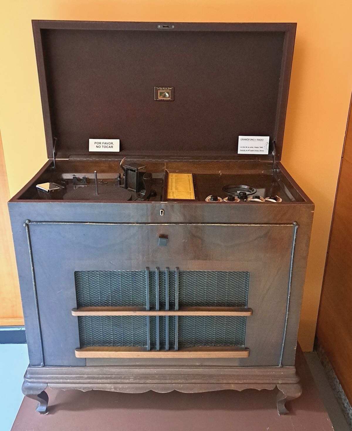
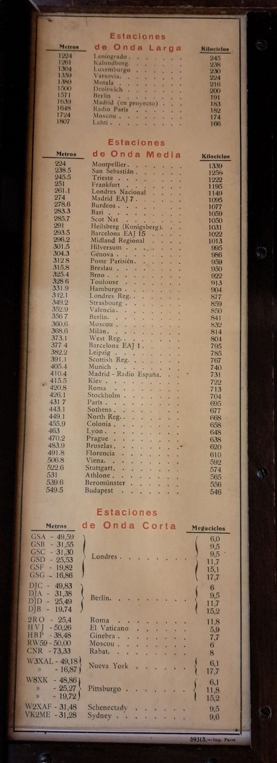
This 1940 RCA radio/phonograph is one of the few items that didn’t belong to Agustín De Castro. What caught my eye was the original station list inside.
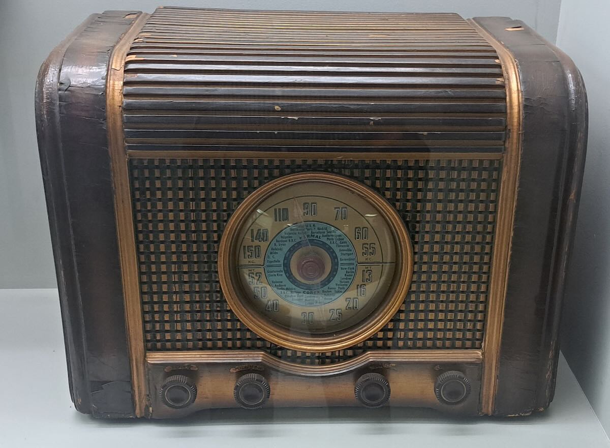
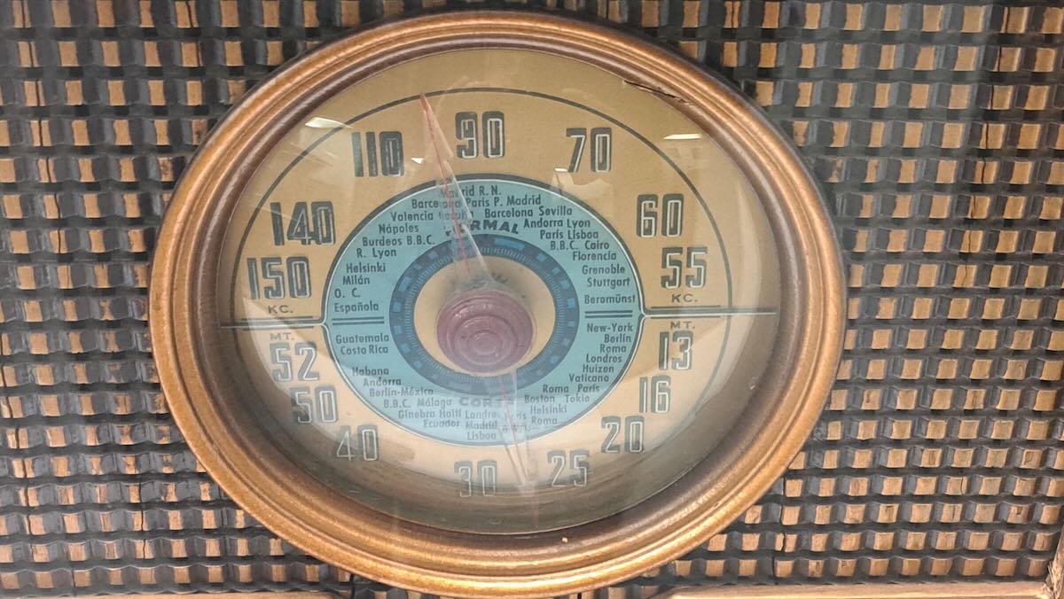
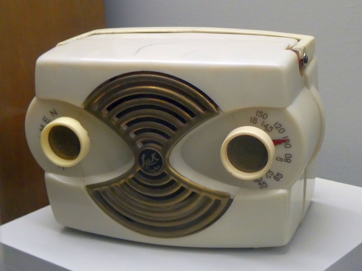
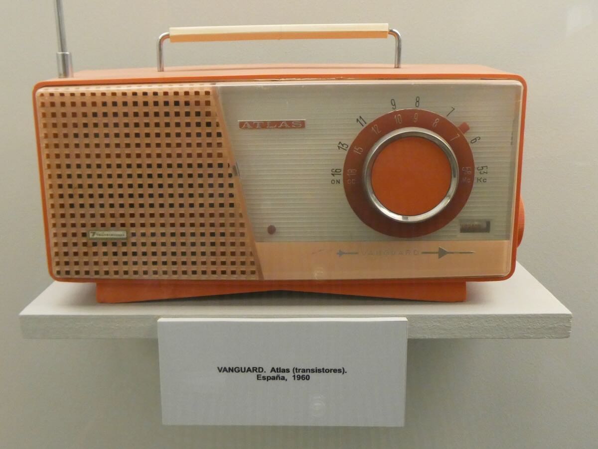
The LAK Radio was a small set made in Spain in 1950. It’s also medium wave and shortwave, but now the shortwave dial has frequencies instead of wavelengths. Likewise, the 1960 Vanguard Atlas from Spain uses only kilocycles.
Two Unusual Designs
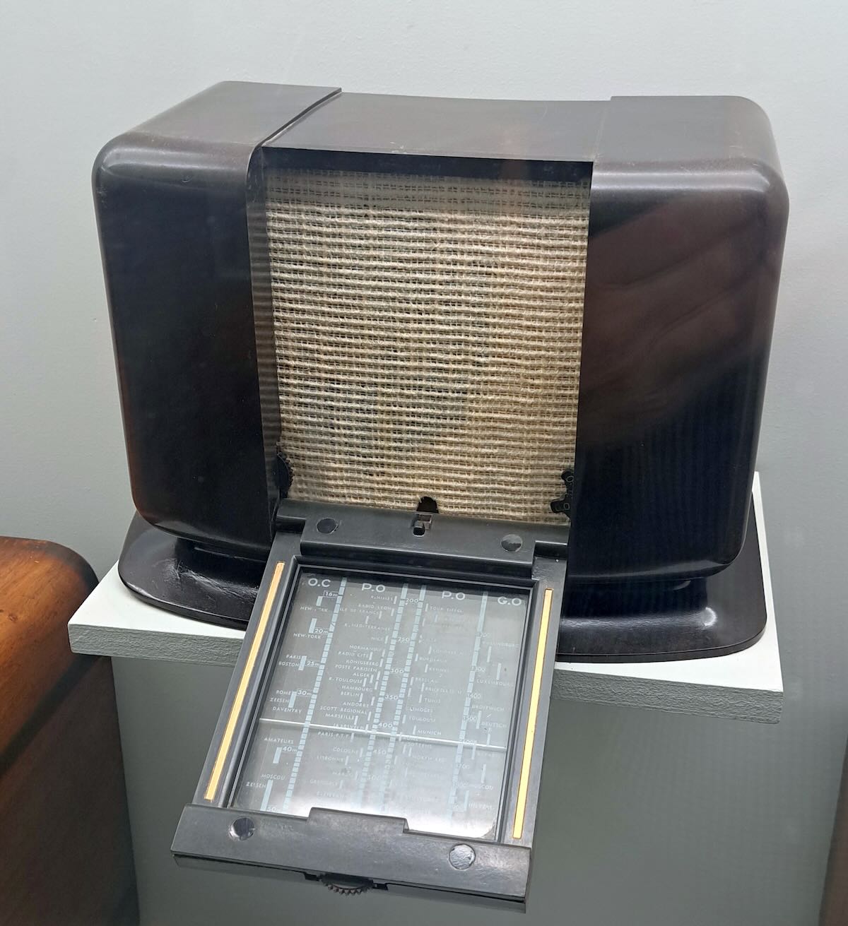
The next two sets will show that there were some rather unusual designs coming out of France. This first set is a Philips A-48-U made in France in 1942. The dial is on a panel that folds down when the radio is being used and then snaps back up when it’s not in use. I think the idea is to give the user a way to put the radio away without having to move it. Notice that the knobs are also mostly hidden. The tuning knob just barely sticks out from the front of the fold-down panel. Two other knobs are at the bottom of the speaker grill on either side.
I wish I could have gotten a better picture of the dial markings on this, but there was too much glare at other angles. The A-48-U was only produced in 1941-42 in Paris, which would have been under Nazi occupation at the time. Nevertheless, the dial still lists Daventry, London, and Droitwich, although it would have been illegal to listen to those British stations in occupied France. The dial also shows New York, Boston, and Moscow, but it’s possible the plates were made before the USA and USSR were part of the war. Continue reading →
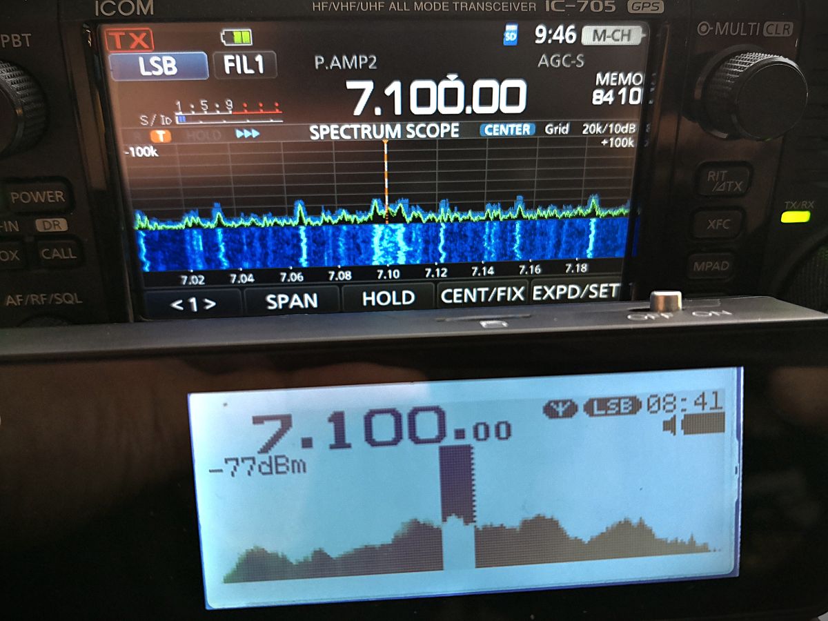
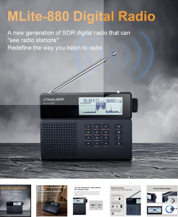
Many thanks to SWLing Post contributor Dan Robinson, who shares the following review:
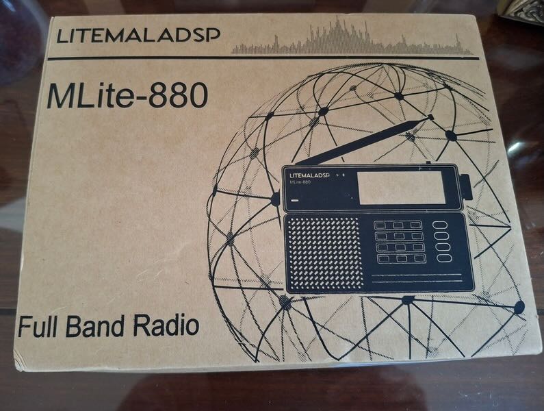
MLite-880 Spectrum Display Portable: Advanced SDR Performance in Traditional Portable Clothes
by Dan Robinson
For years, radio listening hobbyists (as many of us who are still around in 2026) have had numerous choices when it comes to portable receivers. Those of us who got our start as DX’ers/SWLs in the 1960’s (some earlier) or 1970’s have seen a lot of hardware come around the corner.
Some years ago, the Malahit/DSP receivers, firmware, and hardware designed and made in Russia appeared. There was the Belka, amazingly small but a superb receiver that many of us still use. Although shortwave broadcasting has generally been on the decline, we were lucky that companies such as Tecsun, Sangean (reported to have now stopped all production of SW portables), and other China/Taiwan-based companies continued to make impressive portables.
ICOM, Yaesu and Kenwood began putting spectrum scopes in displays a long time ago. ICOM’s IC-R9000 (produced 1989 to 1998) was the first to bring that feature. The more recent Icom 7300, 8600, and 9500 demonstrated far more advanced spectrum displays, as did Kenwood. Ten Tec in its original form put rudimentary spectrum display capability in its RX-350/Jupiter receiver/transceiver.
Today, we’re seeing a number of HT units with some kind of spectrum display. The Radtel 950Pro is one example of this. ICOM’s IC-R30, discontinued but a superb wide band unit, also has a spectrum option though quite limited. Various China-based companies started putting spectrum displays into the ATS series of receivers, and scope displays became standard on transceivers by Xiegu and others.
Malahiteam in Russia licensed firmware out to a range of China-based manufacturers. The China-made “ATS” portables available from AliExpress and Banggood have been through numerous versions, including the ATS25 Pro + AIR desktop, the ATS25 Ultra, ATS25 XF (see https://www.youtube.com/watch?v=LJC-pAu4nUk), and these are increasingly emphasizing the spectrum option on the display. There have been some very interesting front panel designs such as the DP-666 based on the TF6686 chip, and the AMNVOLT ESP138, the first with dual 4732/6686 architecture (see: https://www.youtube.com/watch?v=m1njJskDSUI&pp=ygUMZXNwMTM4IHJHzGlv)
What we had not seen until recently was anyone putting a spectrum display into a “traditional” portable cabinet (some years ago, I had suggested to County Comm/Maratac which has carried a re-badged Tecsun PL-368 that they consider doing so. At one point I received from them a photo of a prototype which looked like a PL-368 with a spectrum display at the top. But to my knowledge nothing was done to advance that to market).
The major feature can be seen at power on. Instead of just a digital/numerical display of frequency we see the frequency AND below, a 40 kHz slice of spectrum. As the advertising description on the Elecevolve.com website states:
“A new generation of SDR digital radio that can “see” radio stations” . . . and “the radio in people’s impressions stays in the last century.”
The message that Malahiteam wants to convey is clear: this is a major step forward from portable design of the past.
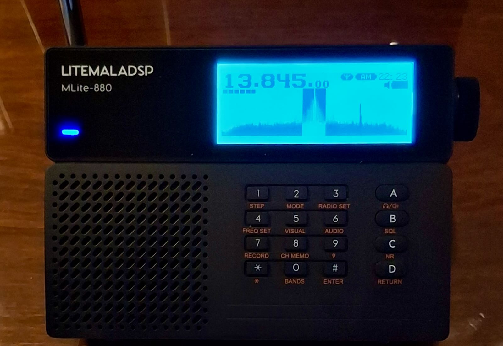
The radio is very light, with a back-stand and a fairly robust whip antenna which stands at an angle when the receiver is being used with the back-stand (unfortunately, the antenna base does not allow it to go vertical).
Around the cabinet, there are a minimum of controls: on top, we have a simple power-on/off switch and a microSD slot (more about that later). USB-C and headphone jack are on the right, and an external antenna jack on the left. The frequency display module of the radio looks like just that — it’s on top above the multi-function keypad and ABCD keys. As for mode displays, there are battery and Bluetooth lights below and next to the LITEMALADSP letters. On the back, we find the 21700 battery compartment, and on the back-stand, we find information about the receiver, but no “Made in…” information whatsoever.
From the videos, and certainly from the name of the radio (LITEMALADSP) we have the impression that the MLite-880 is a cost-reduction version of the Russian DSP/2/3 receivers. Neither 4732 nor TEF 6686 chips are used. While one video review states that an MSI-SDR-M1 chip is inside, Georgiy at Malahiteam states that this is not so.
There was obviously a deliberate choice of the 21700 battery rather than 18650 used in Tecsun, Choyong, and other portables. First adopters say that so far, this battery keeps the receiver going for hours, something I can confirm. Anyone unfamiliar with professional type batteries like this should invest in a good standalone charger; if you already own a Tecsun PLxxx or D808 portable you will be familiar with 18650 and similar cells. [UPDATE]: Larger size 21700 battery does not fit — the battery provided with the radio is a EVE INR21700/50E
The inclusion of a backstand is very welcome, since Russian DSPs and China-made SDR portables often lack one. The whip antenna is not thin and flimsy like those found on some China-made small portables. There’s a mini to SMA adapter included in the box.
One reviewer notes that high-speed microSD cards are needed because files are recorded in WAV format. Georgiy at Malahiteam states that 16 and 32 GB cards have worked, BUT one user reports a 256GB card worked. Recording capability is a feature seen on other portables like the Raddy RF919. A good sized speaker is on the left. The tuning knob has a dual push-pull function for volume and frequency change.
And the radio has Bluetooth capability, which worked fine when I first tried it with a Bluetooth speaker.
In menus under “About” we see “Designed in Russia/Made in China.” I recommend that readers view the various videos available online. While I was in the process of writing, I was surprised when the MLite-880 I had ordered from Banggood showed up on my doorstep. So, I’m able to provide initial impressions, and when a second unit arrives here, I’ll do some unit-to-unit comparisons. [NOTE: Testing done using only the onboard whip antenna]
If this is supposed to be a “Lite” version of the Malahit DSP receivers, whether the original Russian-made units or those from China, that would not be apparent to someone using this receiver for the first time. Numerous options are brought over from the Malahiteam DSP. We have synchronous reception (but see below) and the ability to correct calibration variations. Recalibration and BFO fine adjust is something we see on Tecsun portables, and China-made SDRs, and the AFEDRI SDR.
I won’t list everything, but we also see Hi-Z/50 Ohm, BiasT, Attenuation, and options for adjusting display brightness, spectrum average, spectrum fill, and RDS view. That is quite a lot of flexibility and reminds me of what we find on receivers costing thousands of dollars. Under Audio settings, we see Filter Type, Filter Low Freq, Filter High Freq, and variable Noise Reduction. One reviewer asserted that NR “works significantly better than on the Russian-made DSP-3, which costs near $500,” and based on my first tests, I agree. NR runs from 0 to 15 and, once set, can be quickly activated by pressing the C button on the right labeled NR. Overall filtering ranges: 0 to 8 Hz, 0 to 12 Hz, 0 to 15 Hz for the three designated filter positions.
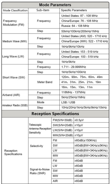
AGC settings include AGC limit, AGC gain, and manual control, all settable in dB. On a third page of options, we find NB Mode, NB Threshold, Equalizer Type, Key Beep Level, and SQUELCH Threshold. Recording is accomplished with a direct access button (NOTE: I had some problems getting record working with a 1GB microSD but switched to a FAT32 8 GB and it worked). A quite nice printed manual shows the modes: USB, LSB, CW, DSB, AM, SAM, NFM, WFM. Steps are listed as: 100 Hz, 500 Hz, 1 kHz, 2.5 kHz, 5 kHz, 6.2 kHz, 8.3 kHz, 9 kHz, and 10 kHz.
The MLite-880 contains band ranges selected by pressing the appropriate key and then A/B to scroll through those ranges. Coverage is from 100 kHz to 519 kHz, from 520 kHz to 1710 kHz, and up to 29,999khz. But one can directly enter any frequency in this entire range, regardless of the ranges. Under AMATEUR BANDS, we find 135.70 kHz to 137.80 kHz (2200m), 472 kHz to 479 kHz (630m), 1800 kHz to 2000 kHz, 3500 kHz to 3800 kHz, 5351.5 kHz to 5366.5 kHz, 7000 kHz to 7200 kHz, and on up to 29.700 kHz, with 70 mHz to 70.5, and 144 mHz to 148 mHz. Finally, FM/VHF bands include 65.9 mHz to 74 mHz (OIRT), 76 mHz to 108 mHz, and AIR band 118 to 137 mHz.
The spectrum display on the MLite-880 is 40 kHz. For most people, especially those coming from a portable with just a digital numerical readout, I don’t think this is going to be a problem. The 880 obviously has a smaller spectrum display than the full Russian DSP or Chinese-originated portables. Under VISUAL settings, we have choices of: BRIGHTNESS LEVEL, BRIGHTNESS OFF TIME, SPECTRUM AVERAGE, SPECTRUM FILL.
I have not opened my MLite-880, but RADIOCHIEF.RU on YouTube shows the cabinet back removed (around the 29-minute mark). We see extensive shielding with metal covers over key sections. Very impressive, and it finds me wishing that other manufacturers would have done this. How much better the short-lived “Elite Satellit” by Eton might have been with better internal shielding.
What remains to be seen is the extent to which the MLite-880 monochrome display throws off interference, a well-known issue with the original Russia-made Malahit units and China-made portables. See my interview with Georgiy of Malahiteam, who notes that not all noise is gone. “We weren’t able to completely eliminate the noise,” he says, adding that “it still occurs in places, mostly on the long and medium wavelengths. However, significant attention was paid to the screening, and turning off the display completely solves the issue.” The screen shutoff he mentions is accomplished as of now by pressing the “9” key.
We learn from the few available YouTube reviews that the main microcontroller in the MLite-880 is the STM32H743, which one reviewer says is “about the same as the older version in the Malahit DSP-3”. And he adds: “It’s a full-fledged SDR like the DSP-3 that is, unlike all sorts of superhet Tecsuns and DEGENs on chips with all sorts of soft mutes, the Malachite works just as well but significantly better. . .”
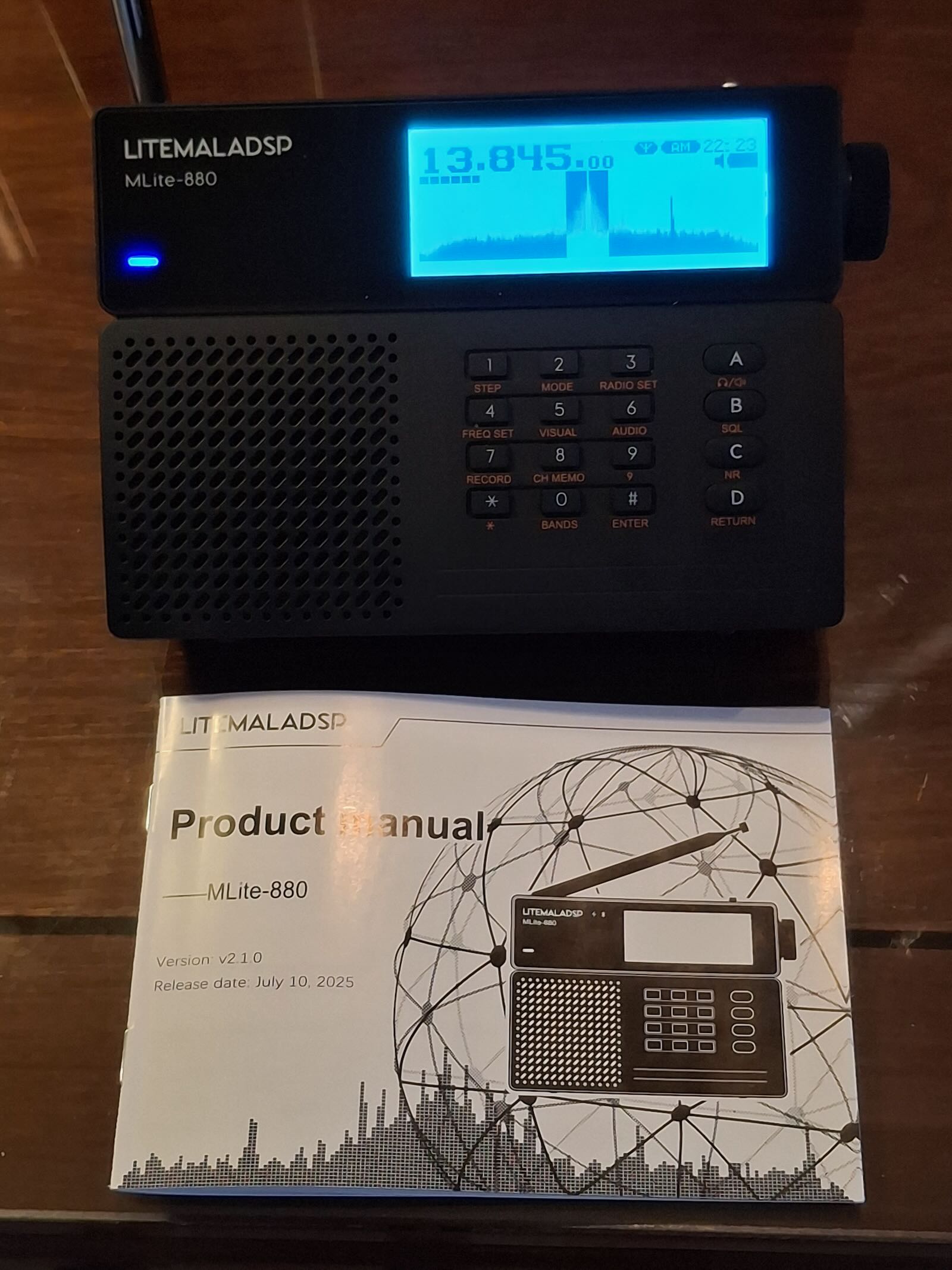
Unfortunately, so far we see that firmware updating is accomplished using the STMCube program used by the Russia and China units and the excellent AFEDRI. I find STMCube to be clunky and often frustrating, though it seems straightforward when explained in the ML-880 manual.
RADIOCHIEF.RU on YouTube provides a demonstration of the MLite-880, comparing it with an ICOM IC-R20 and a DSP-3. He notes that while there are flaws in the 880 they appear to be fixable via firmware upgrades. In the downloads section of the elecevolve website we see version 1.2 dated 6 February 2026. The unit delivered here has 1.1 The printed manual shows “v2.1.0 Release date July 10, 2025”. I’m not aware of videos or other online presence of the ML 880 before January 2026.
WHAT’S THE BIG DEAL?
SWLing Post readers, whether SWLs or amateur operators, may be asking what the big deal is with the MLite-880. That’s understandable, but let me explain the significance. Much as the Choyong LC-90 became the first receiver to provide HF and Internet radio in a traditional radio cabinet (though without any spectrum display), the 880 shows that placing such a display in a traditional portable cabinet has been quite possible for some time — it just took someone to go ahead and do it. Continue reading →
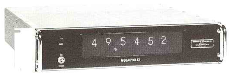
In the late ‘60s, I worked as a mechanical assembler at Communications, Electronics Inc. (CEI) in Rockville, Maryland (acquired by Watkins-Johnson Company). We produced military-grade receivers, mainly for the military (whom else?). These covered the spectrum from VLF through microwave. It was the early days of electronic digital readouts. There were no LEDs or LCDs. Instead, some of our models featured the Numeric Indicator eXperimental, or “nixie” tubes. These were glass tubes filled with low-pressure neon/argon gas, featuring stacked wire cathodes shaped like numerals (0-9) and a mesh anode. An analog-to-digital circuit encoded the frequency to illuminate the correct digits.
Below is shown a DRO-50 Digital Readout from the 1968 CEI catalog. It contained 6 nixie tubes for the frequency display, and the unit had an accuracy of ±100 Hz. Interestingly, this frequency display was designed specifically for the Hammarlund SP-600 Receivers (R-274A/FRR (Army), R-274B/FRR (Navy)). I never saw a DRO-50 come across our line and suspect it may not have gone beyond the prototype. About that time, the SP-600s were ending their military service, so there wasn’t much of a market for upgrades. It would still be a few years before I owned an SP-600 of my own, but how would I love to have one fitted with a DRO-50.
What I had instead of nixie tubes were variable capacitors or inductors, which changed the tuned frequency through a kluge of pulleys and strings, all these hidden behind a Raymond-Loewy-designed bezel and operated by the tuning knob.
What was visible on the front of the radio was an irregular representation of frequencies covering the tuning range of the radio, in other words, the dial. As you rotated the tuning knob, you set the whole tuning mechanism in motion. Signals were progressively tuned, processed, and reported through the speaker or headset as you advanced higher or lower.
Somehow the frequencies never quite agreed with the numbers or divisions on the dial. It could be that the circuits inside the radio were out of alignment. Just as likely, the design of the dial was determined using a preproduction prototype which could not possibly account for the tolerances of the components used on the assembly line.
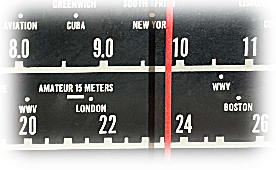
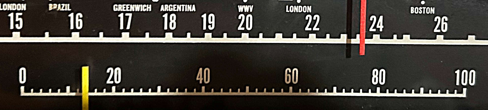
Consider the figure at the beginning of this posting. It is a portion of the dial on a Hallicrafters S-38E – magnified somewhat. The full dial on the E model was big and bright. It extended across the front panel of the radio and presented frequency readout about as well as was possible. Nevertheless, there were real shortcomings.
The figure is not only typical if communication receivers of the time but also living room console radios of an earlier period. Take the 31-meter band as an example. Broadcast stations were bunched roughly between 9400 kHz and 9800 kHz. At 5-kHz channel spacing, this resulted in roughly 80 channels. Of course, not all were in use at any given time, but still a smidgeon turn of the knob could traverse two or three stations.
This situation was relieved somewhat on communication receivers by the addition of a bandspread – a separate tuning mechanism which could effectively magnify a small portion of the main dial. The idea was to place the main tuning dial at the high end of the desired band and the bandspread at 0. Then, by tuning the bandspread toward the other end, lower frequencies could be tuned with greater separation.
Since the bandspread could be used at any place within the tuning range of the radio, a separate dial became a problem, so it was usually annotated with a simple logging scale incremented linearly from 0 to 100. Thus, one had to compile a log-to-frequency conversion table or graph to interpret the frequency. More sophisticated receivers could display the 80- through 10-meter ham bands on the bandspread dials.
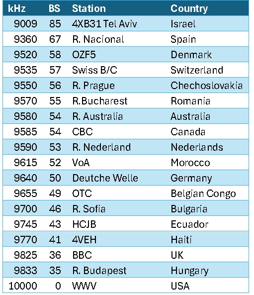
As an example, I located some notes made in 1959 using the S-38E. The table shows the frequency, bandspread reading, station and country. Thirty-one meters was an easy match for the bandspread, as WWV on 10000 kHz was a steady marker which you could use to calibrate the bandspread with the main tuning. For all practical purposes, the band was bounded by the Voice of Spain on 9360 kHz and R. Budapest on 9833 kHz. For many years, Tel Aviv was an outlier on 9009 kHz.
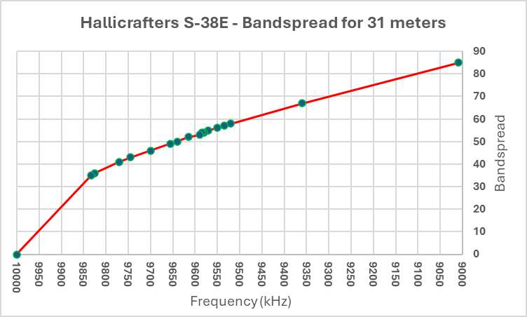
Alternately, one could construct a graph as shown below. Unfortunately, most inexpensive radios did not produce linear tuning, so you couldn’t simply draw a straight line between two points on a graph and expect to interpolate the intermediate frequencies with accuracy. Instead, graphs were constructed laboriously by hand adding intermediate points for known frequencies. The figure shows the resulting parabolic function where the slope is greater on higher frequencies and gradually levels off as the bandspread is tuned lower. Notice that most of the activity was mashed between 40 and 60 on the bandspread, then compare this with the picture of the bandspread above.
On the S-38E a bandspread was something of an improvement, but not the complete answer. The problem only got worse as you went higher in frequency. At 19 and 16 meters the band compression became quite severe.
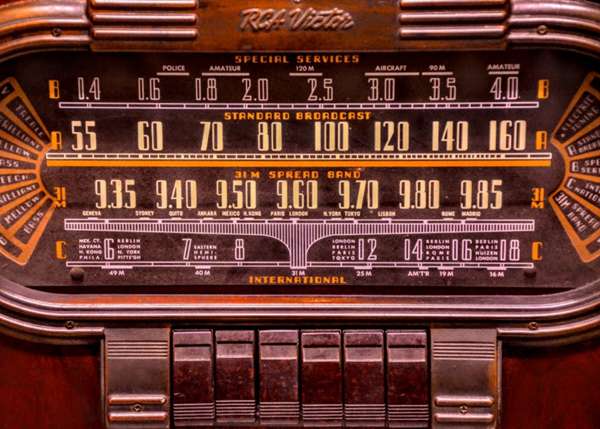
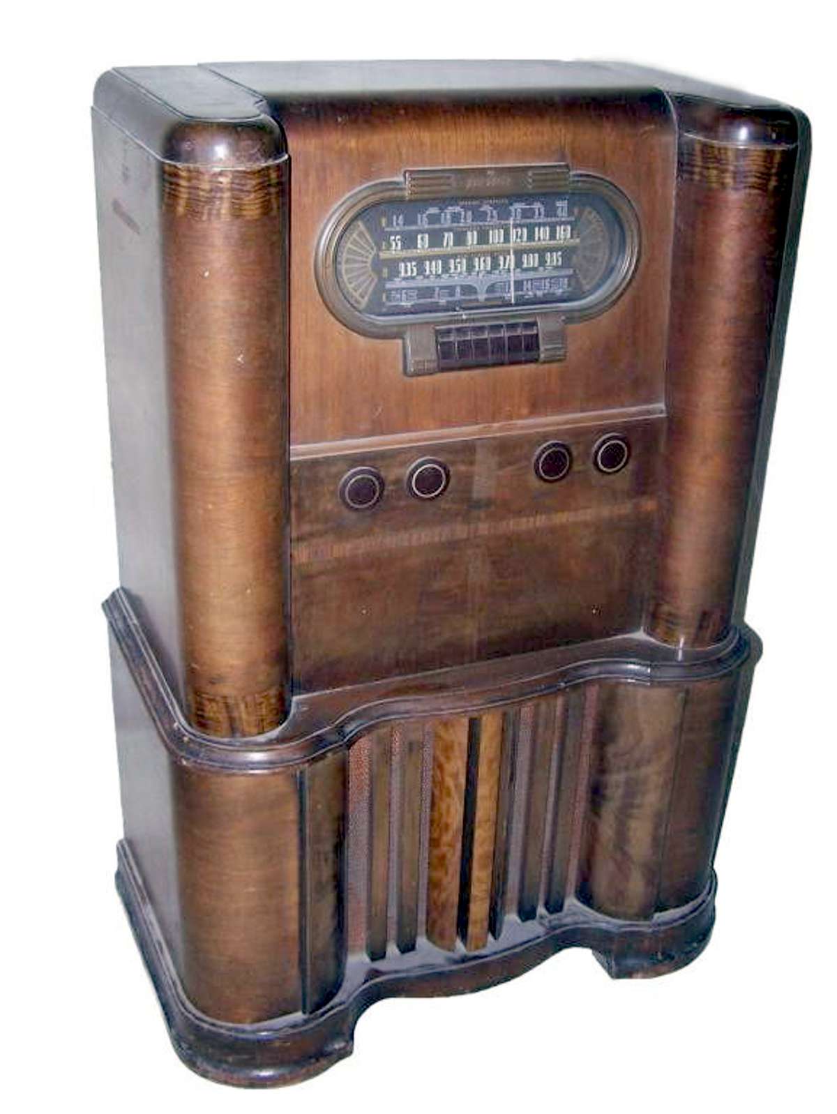
Our esteemed leader, Thomas, occasionally uses a picture of the dial shown below as a lead figure of a posting. It is possibly an RCA Victor Model 110k console radio. When I see this, I think, who wouldn’t give a king’s ransom to own that radio in its fully restored condition? Note the 31-meter band has been magnified as its own separate band and appears in a near linear progression. Thirty-one meters was arguably the center of international shortwave broadcasting in the golden age.
Have you ever wondered what the rest of that radio looks like? Here’s one in sore need of some Pledge. Now imagine yourself, perhaps 11 or 12 years old, perched in front of it on your grandmother’s needlepoint stool tweaking the dial. If you have experienced this, no explanation is necessary. If you haven’t, none is possible.
So, as it turns out, I have tempered my earlier conviction that a digital frequency readout is necessarily better than a classic dial. Not to say you can easily pry the PL-880 with 10-Hz resolution from my cold, stiff hands, but I have come to realize that intrigue and mystery of shortwave listening rested in the uncertainty of knowing exactly what frequency you were on. There was always the possibility that the elusive Nibi Nibi Islands lay somewhere near the shadow cast by the dial pointer. It was a land of enchantment, and once you left its borders, you could never return again.