
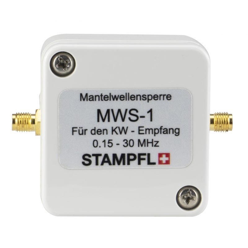
Many thanks to SWLing Post contributor, Markku (VA3MK), who notes that Swiss manufacturer Stampfl has introduced the MWS-1 Standing Wave Barrier.
Stampfl notes (translated from German):
A standing wave barrier can improve reception. The standing wave barrier interrupts the ground loop and suppresses the interference caused by the cable shield.
This is designed only to work with receivers (not transmitters) between 0.15 – 30 MHz.
I suppose this might be a form of an RF choke, although I’m sure someone else might know better.
Thank you for the tip, Markku!
Standing Waves:
When a signal is sent down a cable the feeding and receiving impedance should be equal and matching the characteristic impedance of the cable. This ensures that all of the signal is delivered to the receiver.
If the impedance does not match the additional power has to go somewhere so it travels back up the cable. It is adding to the signal at that point. So in some places the signal will increase in amplitude and in others it will cancel out and possibly leave you with no signal at all. This will happen at regular intervals along the cable, if it is long enough.
Ground Loops
A ground loop only occurs when there is multiple connections to earth. So the best option is to earth the screen in the coaxial cable as close to the source as possible. Ie if you use a balanced to unbalanced (balun) transformer on the antenna, earth the screen of the coax cable at the point to an earth stake in the ground which is best. You will note that many receivers are either battery operated or have a two pin power plug. As a result there is no other earths to create an earth loop. If there is no coaxial cable used to the antenna, an earth connection to the sleeve of the headphone plug could reduce the noise.
The only possibility is where you plug in something else which is mains powered and has a 3 pin plug. Then the earth will be connected in the signal path creating an earth loop.
Note for minimum noise there must be one connection to a ground (earth). A piece of copper pipe, a metre long depending on soil conductivity is required. If you are in an apartment you will need to use the earth wire from a power point. This however is not as good, but is usually the only option. This is because mains powered equipment often has a filter in which one side of the capacitors are connected to the earth wire so there will possibly noise currents in that wire.
Please note: To connect to the earth wire in a power point may be illegal in some countries because of the possibility of miss wiring of the power plug, which can cause death by electrocution. You cannot see if a piece of equipment is “live”.
I can see the point of a balun connected to the antenna, as virtually all TV antennas contain them, but I don’t see them as an additional add on accessory!
@Alexander, DL4NO
They doesn’t say it’s a balun either.
Besides, a galvanic isolator also breaks a ground loop…perfectly. I have several of them here and I have several self wound baluns and common mode chokes. They all serve me well in different situations..
The real problem (if one could call it that 🙂 ), is that the manufacturer does not use any of the usual names for such a thing.
@Geir Laastad: The German documentation says nothing about galvanic separation. It only says “it breaks the ground loop” which is what a it should do – for radio frequency! BTW: Any form of transformer would not have such a flat frequency response and 1 dB off attenuation at 150 MHz.
So: If you want to have a polished product from Europe, buy this. Otherwise have an hour of fun and build it yourself. As long as you avoid any silly mistake you cannot make a real error.
I am surprised by your assertion that “Any form of transformer would not have such a flat frequency response and 1 dB off attenuation at 150 MHz.”
I am not sure where the figure of 150MHz comes from as this product only claims to cover 150kHz to 30MHz?
With regards to the flat frequency response, I suggest that you look at the Mini-Circuits range of transformers, for example the ADTT1-6+, which offers a 1db insertion loss between 60kHz and 30MHz and a 3db insertion loss between 15kHz and 100MHz.
https://www.minicircuits.com/pdfs/ADTT1-6+.pdf
Alexander, DL4NO
The manufacturer’s specifications state that the “Einfügedämpfung” (insertion loss) is “< 1db".
The "Dämpfung" (attenuation) noted is in reference to it's performance in noise suppression.
https://www.heinzstampfl.ch/wp-content/uploads/2021/09/MWS_1.pdf
The 1 dB is the attenuation of the two connectors and a few cm of thin coax. You cannot build a transformer with such a wide frequency range and only 1 dB of attenuation. Without a transformer you get no galvanic separation.
Loss that occurs while a signal is traveling through a component or system is referred to as Insertion Loss. . THROUGH THE SYSTEM! The System in this case is the whole device to include it’s components. From front to back is the Insertion Loss. Take that up with the manufacturer’s specs if you disagree.
I don’t think this is a balun, but a “galvanic isolator” as it usual is called.
I suspect this is nothing but a 1:1 ferrite core isolation transformer which not only galvanically isolates the antenna feedline shield from the receiver chassis “ground”, but at the same time will also function as a feedline choke since it will force the feedline currents to be identical. I made several of these years ago when I did longwave DXing and they were imperative for noise reduction.
A N2DU 1:1 balun is a very easy and rewarding home-brew project. For $ 10 you can buy the materials and use the sockets you want: housing, sockets, a length of RG-174, a ferrite ring. I have enough ferrite rings for this purpose in my junk box.
The most obscure thing about this project is die 40 dB attenuation the manufacturer claims: dB’s are a ratio – between what? You could short-circuit the sockets and measure an impedance between the sockets. Do they mean the ratio between this impedance and the 50 Ohms of the cable?
Chokes can be reported as dB attenuation *of common mode signals.* You set up your VNA to pass a signal on the shield and measure the attenuation. Not your typical way of reporting, but it gives you an intuitive idea of how much common-mode noise it might suppress, if that’s the concern.
How do you “pass a signal through the shield”? You need two conductors to do so, not one.
All you can do with one conductor is to measure its impedance. In that case you close the circuit on the outside through the measuring equipment. I still see nothing where you could compute any ratio. Therefore there are no dBs available. Therefore the dBs in the data sheet might be the ratio of common-mode impedance and characteristic impedance of 50 Ohms.
40 dB is a power ratio of 10,000 to 1. Lets assume you build a voltage divider you need a ratio of 100:1. If the “lower” resistor has 50 Ohms, the “upper” impedance must be 5,000 Ohms. Take a frequency of your choosing and compute the impedance of a 1 pF capacitor at this frequency…
What many of you simply ignore are the capacities between the primary and secondary windings of a transformer. You must especially consider that you must minimize the magnetic stray fields within the transformer: Since the first audio transformers in the 1920s it is known that you must interleave both windings. For RF transformers you most often twist the wires of primary and secondary windings.
Looks like a 1:1 balun or choke similar to a Winradio version I have. Their preselector kit also looks interesting to provide band pass filtering to a wideband sdr.