Many thanks to SWLing Post contributor, Kris Partridge, who shares the following antenna construction article from Radio World:
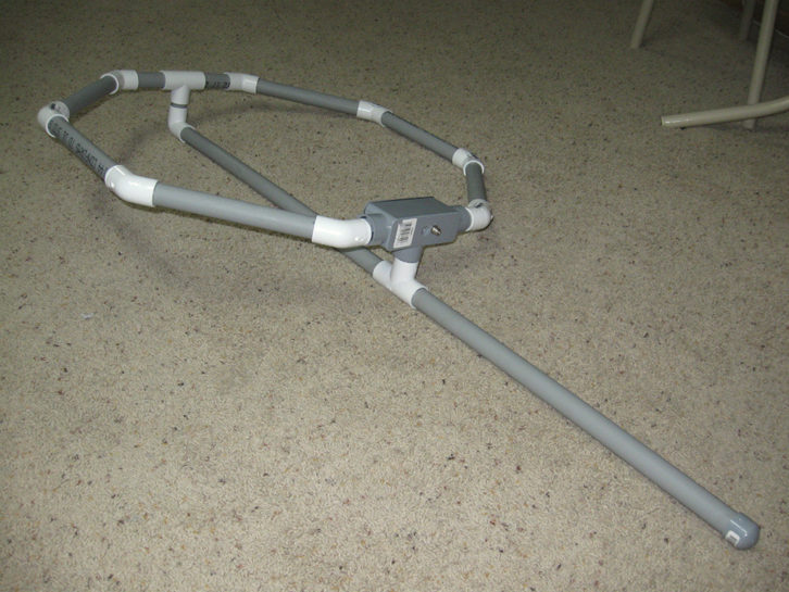
Ken Beckwith is a field engineer with EMF based in Nebraska. Being a hands-on engineer, Ken has done his share of construction over the years. One of his projects was the construction of an octagonal-shaped AM loop EAS antenna using PVC pipe.
[…]The antenna has a broad coverage angle with a deep null when the antenna is broadside to the signal. Aim the “edge” of the loop toward the AM station you want to receive. The strongest signal will be received when the antenna end or edge is pointing to the signal source. The antenna can be mounted on a mast with U-bolts, hose clamps or whatever else works.
Here’s the construction parts list:
A 10-foot length of 3/4-inch diameter, schedule 40 PVC conduit cut into the following lengths:
2 – 4-inch
1 – 2-inch
1 – 2-1/4-inch
2 – 2-1/8-inch
6 – 9-1/2-inch
1 – 23-1/4-inchWhatever is left over can be discarded, but before making your cuts, cut the flared end off, so all cuts are even.
1 – 3/4-inch 90 degree elbow
2 – 3/4-inch tee
8 – 3/4-inch 45 degree elbows
1 – 3/4-inch cap
1 – 3/4-inch tee box, plastic, with weatherproof gasket
1 – 7-foot piece of Belden 8777 or other three-pair shielded cable
3 – 7-foot single-pair shielded cables can substitute for Belden 8777
PVC primer and cement
Wire nuts or other connectors
1 – 3/8-inch ring terminal
F connector barrel with nut[…]
Click here to read the article which contains step-by-step instructions.


It’s an … interesting … design.
Not sure about it’s principle of operation as a ‘loop’ loop though – it’s basically wired as a shielded unbalanced H field probe (e.g. type 2c at http://www.compliance-club.com/archive/old_archive/030718.htm), with added distributed capacitance from the multiple turns of the centre conductor running back through the shields. I wonder if its performance is due primarily to that capacitance making it broadly resonant across the MW AM band?