
Many thanks to SWLing Post contributor, Bruce (VE3EAR), who shares the following:
I live in the village of Saltford, ON, Canada, near the eastern shore of Lake Huron. It’s a quiet location signal wise, and I’m lucky that I have enough property to erect some big antennas. My two favourites are a 1200 foot long terminated Beverage, aimed at 50 degrees true, which targets Europe and the UK. The other is a 333 foot perimeter delta-loop, apex up and oriented north-south. Both antennas are fed with RG-6 coaxial cables and impedence-matching transformers.
I use the loop with a recently acquired Airspy HF+ Discovery SDR and the Gqrx SDR software, in my iMac. I like to listen to amateur activity on 160, 80, and 40 metres, along with the few shortwave broadcast station that are still on the air. I also like to listen to the trans-Atlantic air traffic control stations in Shannon, Ireland and Gander, Canada.
I once heard a U2 spy plane returning from a mission over Russia!
My other hobby is designing and building simple, one transistor regen receivers, most of which tune the AM broadcast band, although I have built a couple covering the lower portion of the HF broadcast bands as well, just for a challenge. All my receivers are built breadboard style.
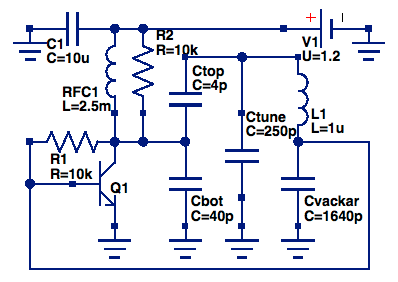
My favourite of them is one based upon the Vackar oscillator, with the addition of a diode detector and “Benny”, as is used in crystal radios.
Here is the schematic of the Vackar circuit:
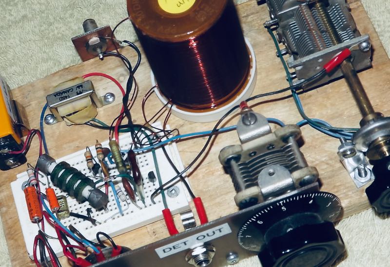
The diode and “Benny” connect to the collector of the transistor, then to a pair of home made headphones using two telephone earpiece elements installed in a pair of hearing protectors. The receiver is both very selective and very sensitive. Here is a pic:

Most of the electronics are on a proto-board, which allowed easy component substitutions during the build. When I had it optimized, I decided to leave it that way! The controls, left to right, are on-off switch, regen, fine tuning, main tuning, and range selector switch, hidden behind the reduction drive. Audio is taken from the DET OUT jack, to either the headphones described above, or to an audio amplifier for listening with a speaker.
Bruce, it sounds like you certainly have an excellent spot and excellent antennas for DXing! I love regen receivers as well and radio design can hardly be more simple.
Thank you for sharing!
Very intersting assembly. It can be also turned to emetter with only some modifications on the initial schema 🙂
I too am a fan of single transistor regen radios. I’ve developed a different topology than yours, and do not need an external antenna or ground to get fantastic reception, from broadcast band up through about 7MHz, albeit at the “top end” performance drops off substantially! The neat part of my rig is that it can be operated with the receiver oscillating, and there is a “lock in” capability that substantially mitigates [but not eliminates] frequency drift. On one exceptional reception night, I listened to a guy in Wisconsin talk to a guy in Germany, 80M SSB. The SSB reception is enabled by the fact that the receiver is oscillating…
The origin of this topology is lost in the “distant past” but I discovered it in a childhood project when I cleaned out my old man’s house after he passed. There was a wiring mistake and it never could have worked, but that got fixed and the set worked great with a 2N169 transistor with a ’56 date code. with an e-mail address I’d be happy to share the schematic with more discussion. My build quality is, ah, “function
over form, I’ve a “round tuit” project to make one that is “pretty”: I’ve built two of these for friends… One using a CK722 vintage transistor, and one with a more modern device. Hearing aid receiver for listening,
also transformer matched.
Cheers!
Terry
Could / Would you come up with a simple design to add Regeneration to small Loop Antennas?
thanx
73 de jordan ve7jjd jjdobrikin @gmail.com
Steve….Email your questions to: [email protected] and I’ll be happy to fill you in on the finer points of the radio.
73, Bruce, VE3EAR
Steve….sorry for late reply….been rather busy lately. The transformer is a Hammond 142D with 200K:1K
ratio, the latter connected to the headphones. The “Benny” is a 180K resistor in parallel with a 0.22 uF.
cap, both in series with the transformer primary, to make the DC resistance equal to the AC reactance.
The regen control is just a voltage divider across the 9V battery. The antenna is coupled with a 3 turn
link winding at the cold end of the the tank coil.
Could Bruce give some details on the circuit?
Where does the antenna connect in the circuit?
It appears that the Regen control is a potentiometer. Which resistor is this in the circuit diagram?
The “Benny” apparently is the audio transformer. What’s the impedance ratio for it?
The battery appears to be a 9V battery, but the circuit diagram shows a 1.2V battery. Which is it?
What diode, R and C do you use in the detector?
Thanks for presenting such a simple but probably effective design!
Turn up the gain high enough and you have a transmitter.
Well done!! And your build quality is exceptional!’ Stay safe, Mark. N8JCF