
Many thanks to SWLing Post contributor, Zach R., who shares the following guest post:
A review of the outdoor Planespotter antenna prototype
 When it comes to airband monitoring, the stock whip antennas that ship with desktop and portable scanners are not the greatest. They’re fine if you’re at an airport and only interested in communications specific to your immediate area, but if you are someone like me who lives well out from any major airport, quality listening in can be impossible without some help in the antenna department.
Ideally, you want something like a discone or similar for omnidirectional listening, mounted as high as possible. This is not always possible or practical, however. SWLing Post contributor Ron recently reviewed the indoor Planespotter antenna, and I have one as well that works better than any rubber ducky, and can be easily hidden away when company comes.
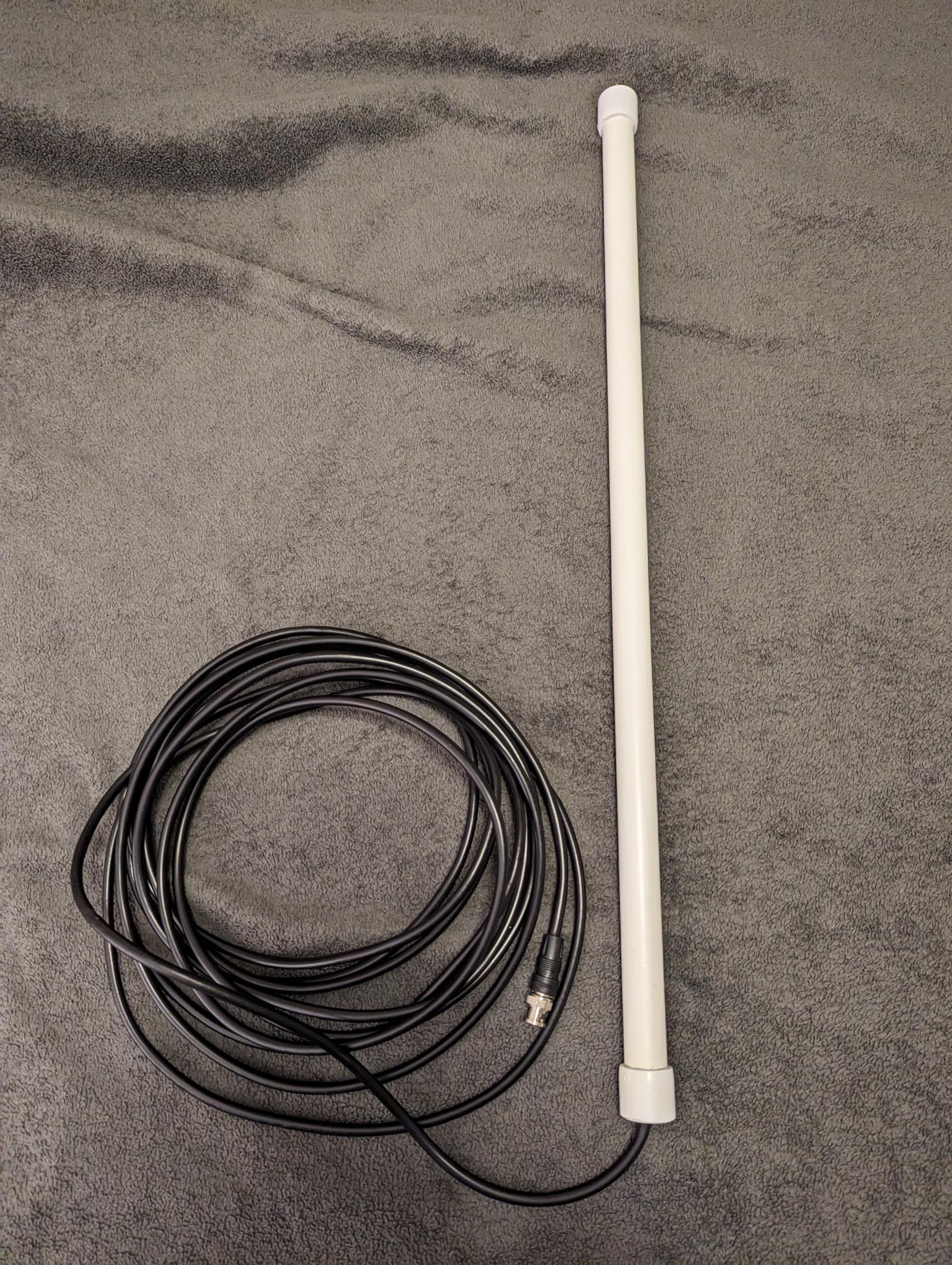
Recently, the creator has come out with a prototype outdoor model. It’s the same design as the indoor unit, but with a longer run (25 feet) of coax, terminating in a BNC connector.
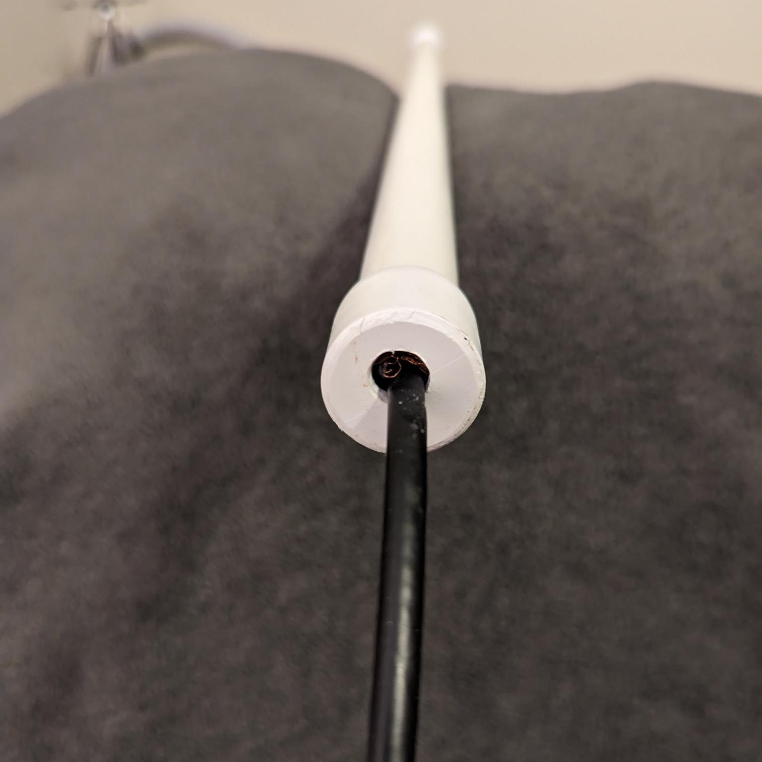
Besides the longer cable, the only other obvious change is the antenna is house in a skinnier PVC tube from the indoor model. It’s also sealed at the bottom so moisture won’t get in.
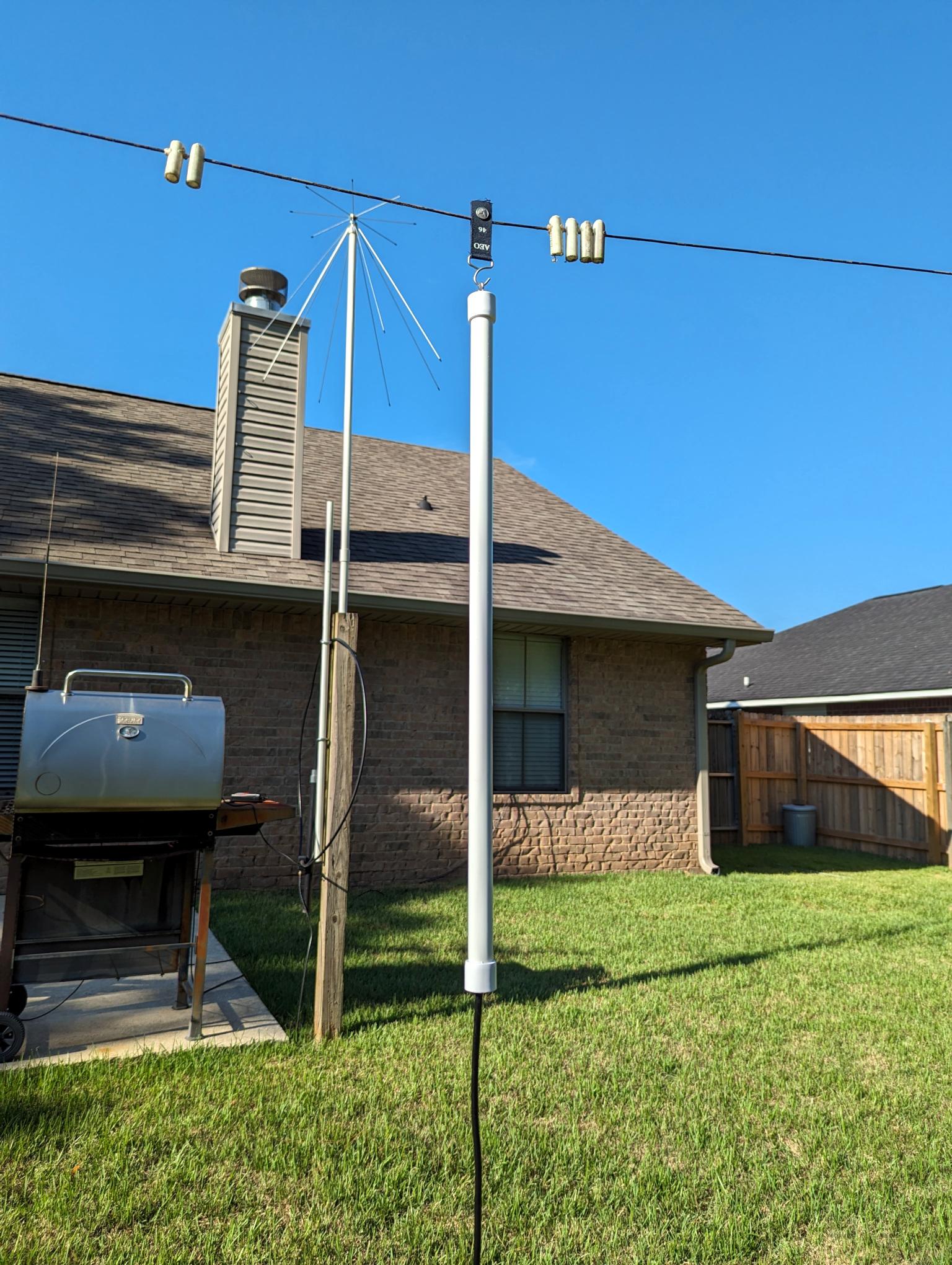
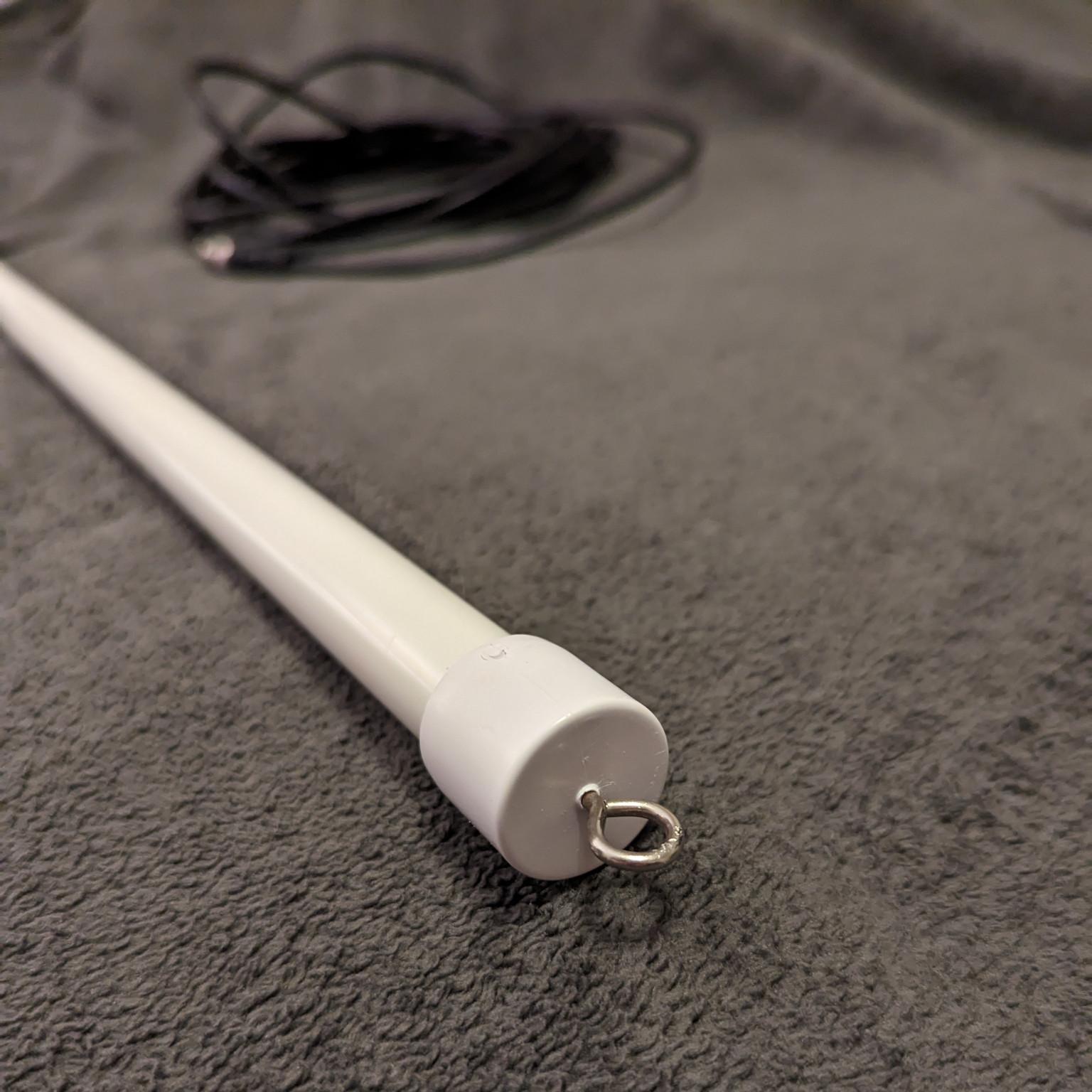 It has the same small metal hook on top, suitable from hanging from various mounts. I’d like more mounting options, but the hook does make for quick installation and removal. The half-wave length isn’t ungainly to handle and if painted it could easily be mounted on the side of a home without many people noticing.
The indoor version definitely works best on the VHF air band and seems to roll off aggressively above and below that band. The outdoor version, in side-by-side tests, seemed to perform the same on the air band but notably better on the VHF public safety band. It also pulled in more UHF air band traffic than the indoor model, despite being basically the same design.
The new outdoor version is a good choice for someone looking for a simple, already assembled antenna that’s suitable for temporary use or stealth mounting.
Disclosure: The outdoor prototype was supplied to me for free in exchange for a review. While taking more photos of the antenna I noticed the weatherproofing had come undone from the bottom. Hopefully this issue can be addressed before the antenna goes into production.
[Zach R. is the owner and editor of the Alabama Broadcast Media Page.]
I see what you mean. I guess the only way I’ll know for sure if it really matters for my purposes is to build one and find out. But, I’ve got my hands full with some other things so that is a rainy day project for the future.
the build should not take more than 20 minutes, assuming one has collected all the bits and pieces, for the upper half of the antenna, use a piece of stranded, insulated wire soldered to the center conductor of the coax and pick a pipe longer than needed, say 1/3 more, the bottom part will be useful to hold the antenna tona pole, if needed, the remainder is pretty straightforward
oh and if you want to discuss the antenna, feel free to join the SWLing forum at https://swling.net 😀
An RF-Choke and the use of a VNA will reveal the efficiency of an antenna. You must aim for a high – Return loss number with the coax and plugs included in the measurement. I make antennas, chokes and baluns as a hobby and I experienced very soon that a VNA is an essential tool to get things right. No guess work, measuring is a must.
When mounting the antenna outdoors, do provide a small condensation hole in the bottom where the coax leaves the cage.
There are no voice transmissions below 118 mhz in the VHF airband.
Below 118 mhz is reserved for navigation stuff like VOR,etc.
That’s why this antenna is cut for 118-137 mhz.
Very timely! I have been experimenting using a RTL-SDR rabbit ear vertical dipole up here in my Indonesian home as I’m an aviation nut and want to hear the overflights on the W46 which is directly above me and G464 airway which is close enough for me to eyeball the aircraft lights at night. G464 is a busy airway for most of the Singapore (and many other SEA hubs) to Australia & New Zealand.
I was surprised that here with the rabbit ears just attached above the gutter line I am even receiving well the Airway Clearance and Ground frequencies at WADD over 50km away (Denpasar Bali International) as well as the Tower, Director, and all surrounding Ujung Control frequencies. So….
Last week I got hold of a Diamond BC100S Commercial Base Station ground plane, it’s designed for transmitting but I’m only going to be using it for receiving. Its designed for 115 MHz to 174 MHz and you trim (i.e. cut) the element to the frequency you are going to use. So I’m thinking for my purpose I would trim the antenna for 126 MHz – the middle of the VHF airband – is that what most of these air-band scanner antennas are tuned to or int the middle of the band the convention for tuning an antenna?
Opps the last sentence should say….
is that what most of these air-band scanner antennas are tuned to? Is the middle of the band the convention for tuning an antenna?
Wow! I bet there is a ton of interesting activity in that region. There are no major airports where I live, but we still manage to have a pretty active air band scene thanks to several small airports as well as all kinds of military flight activity from Pensacola Naval Air Station and Eglin AFB. I can only imagine how busy it can be on those flight routes around you, though.
126 MHz sounds like the right choice to me. The Planespotter indoor antenna is supposed to be cut for resonance at 127 MHz.
Neat, 126 it is – thanks Tom!
…and noted is the use of the ‘Ground Plane Grill’ antenna 🙂
An easy Saturday afternoon rainy day project
John
As a note, installing the antenna so that the bottom is about at 0.6 Lambda (around 1.5m from ground for the airband) the antenna will show a gain above 3dBi with a radiation solid allowing to pick up signals at angles between 45° and 10° from the horizon, this means that the antenna will be fine to pick up signals from pretty long distance but won’t work so well for aircrafts flying right “above your head”, willing to pick up the latter one may install the antenna at about 0.25 lambda (0.5m from ground), in such a case the gain will get down to 2dBi but the lobe will cover from 75° to 10° from horizon so allowing to better pick up signals from aircraft “flying just above”
That’s interesting information, Andrew!
another flowerpot antenna, that is an 1/2 wave sleeve dipole, but apparently w/o a choke at bottom, bad idea, since the line will cause issues, also, what’s the price for that piece of coax plus PVC pipe ?
https://vk2zoi.com/articles/half-wave-flower-pot/
No price yet since it’s a prototype.
The production version may be a bit different with a mast clamp,etc.
The indoor version goes for $ 37 usd plus shipping.
Presumably the outdoor version won’t be very much
more for the 25 feet (7.6m) of coax.
According to his website he does ship to VK land…73.
What issues do you see with the choke missing?
The parts are cheap, the price is for the convenience, I suppose
The choke in this case is also used to “define” the length of the radiating (receiving) element, w/o it, the antenna will be detuned since the coax feeder line will act as part of the antenna, and sincerely I can’t see why it was left out, winding some turns of coax around the pipe hosting the antenna wouldn’t add so much cost and would result in a better antenna, that being said, building one of those antennas isn’t so difficult, there are online calculators like this one
https://nomonsuhendar.blogspot.com/2020/12/flower-pot-antenna-calculator.html
and a number of examples and “how to” can be found online, so while one could just go for the “ready made” one, building such an antenna won’t be a big hassle and will surely be cheap
In case those of you who are hams haven’t
noticed,ten meters (and CB) are doing quite
well lately.
Check this map to see the Maximum Usuable
Frequency in your area:
https://prop.kc2g.com/
The K6FRC beacon on 28.300 is making it to the east every day.
Thanks for the insight into the choke’s purpose. I do wonder just how important it is for reception, though. The only other vertical I have to do any kind of comparison with the Planespotter is a 2m mag mount vertical pulled off an old car. Honestly, the Planespotter outdoor version did at least as good as the vertical, usually better. It was only on the rest of the VHF band (or FM broadcast band) that it really did worse.
Tom, please start by having under your eyes the pic of the “flowerpot”
https://vk2zoi.com/articles/half-wave-flower-pot/
now, the antenna is a vertica sleevel dipole and the “real” feedpoint of such a dipole is the midpoint where the single (upper) wire joins the bottom (coax), now… the two halves of such a dipole (upper and lower) should have more or less the same length, but if we remove the choke, the whole coax feedline will become the “lower arm”, this will detune the antenna, alter its radiation (reception) pattern and reduce the gain
see it now 🙂 ?