 Many thanks to SWLing Post contributor, Frans Goddijn, who shares the following article and video originally posted on his blog:
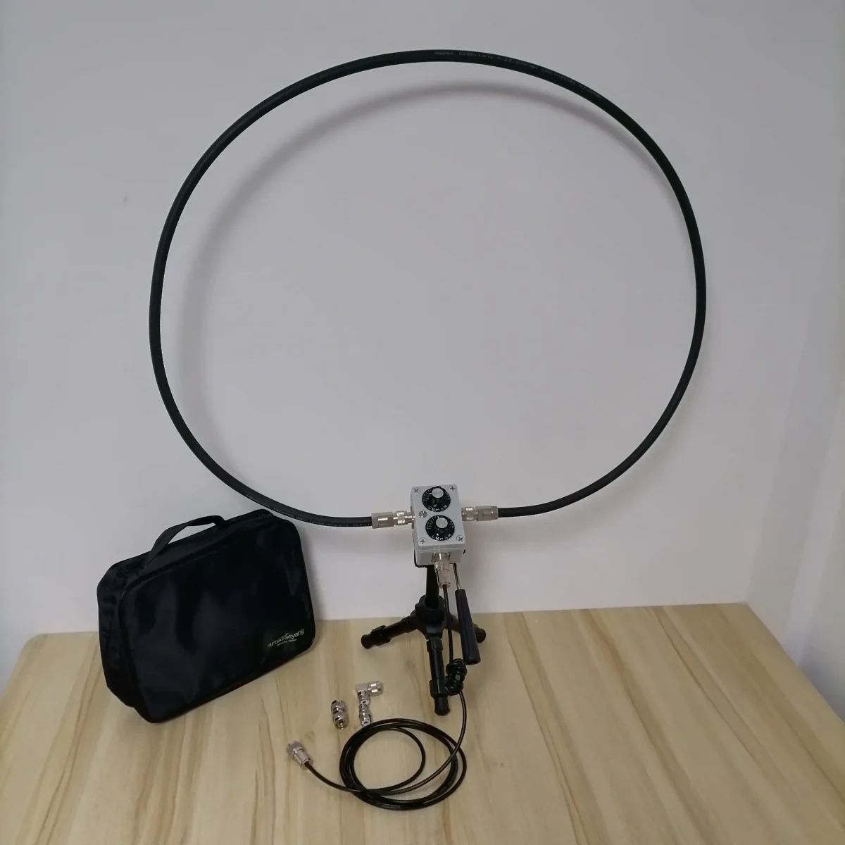
I got the little BH5HDE QRP portable QRP loop, assembled it and could not wait to try it out even though it was during that day and signals were sparse and weak.
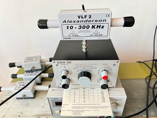
This new loop performs well, in part thanks to the tuning & impedance knobs. I compare it with the GRAHN SE3 and a big home made loop that I bought second hand. The latter has no tuning but is as directionally sensitive as the others and it delivers an amplified signal to the receiver.
Click here to view on YouTube.
I found a manual for the QRP, not included in the package:
Instructions for use of BH5HDE QRP portable small loop antenna
Welcome to use the BH5HDE QRP portable small loop antenna. This product can easily and quickly set up a short-wave transceiver antenna, allowing you to enjoy the joy of multi-band reception and communication indoors, windows, balconies and outdoors.
Installation:
(BNC mount equipment needs to bring a pair of photography tripods)
Use the right-angle adapter and double male docking to connect the antenna to the m seat at the rear of the radio station or erect the ring body to the connector on both sides of the controller and tighten, then install the tripod to the fastening seat on the back of the tuner Open the tripod, place the antenna body firmly on the tripod, and finally connect the feeder (the feeder is attached with a choke, one end of the choke is placed near the small loop antenna).
use:
Now that the small loop antenna has been connected to your radio station, you can now tune in.
First introduce the function of the tuner panel. The toggle switch on the left is the band selection switch (up: 7MHz, down: 14-30MHz).
The main control knob, the upper knob is the frequency tuning knob, the frequency tuning value does not change due to environmental changes; the lower knob is the impedance matching knob, the impedance matching value will change due to environmental changes. (The tuning range of the two knobs is 180 degrees, and the panel value is 0-60).
When you start using the radio, select the desired frequency, and then turn the band switch to the desired band position, then adjust the impedance matching value of the lower knob to 30, and then adjust the upper knob to tune. At this time, pay attention to listening to the noise floor of the radio station. The more resonance, the louder the noise floor of the radio station (in the environment with extremely low noise floor, the antenna resonance noise floor is almost inaudible. It is recommended to let the radio station observe the standing wave). At this time, let the radio transmit (cw, fm, and am modes are available), pay attention to the standing wave indication, and fine-tune the frequency tuning knob while transmitting. Since the knob of the portable version does not have a deceleration function, the method of fine adjustment must be more delicate, and the smaller the rotation angle, the better.
At this time, you can observe a significant change in the standing wave, but generally the minimum standing wave ratio will not be below 1.5. At this time, you need to adjust the impedance matching knob. It is recommended to adjust the positive and negative 5 scale values randomly, and then repeat the frequency tuning steps and observe The standing wave ratio. Due to the change in the matching value, there are two possibilities before the comparison: 1: the minimum value of the standing wave ratio decreases; 2 the minimum value of the standing wave ratio becomes larger. If the minimum value of the standing wave ratio becomes lower, it means that the impedance matching adjustment approaches the correct value and can be further adjusted. If the minimum value of the standing wave ratio becomes larger, it means that the impedance matching is far from the correct value and must be adjusted in the opposite direction.
Repeat the above steps to adjust the VSWR of the antenna to 1.0.
The VHF and UHF bands are fixed with the upper knob hitting 60 to the end, and the lower knob can adjust the impedance to resonate.
Note: The best effect for outdoor use is to use antennas indoors as close as possible to windows, fully enclosed reinforced concrete, against walls and other environments where the standing wave ratio is not ideal.
Advanced technique: when the signal is weak, you can rotate the antenna direction to improve the signal-to-noise ratio, which is conducive to reception. The unique gain lobe of the loop antenna makes the horizontal gain directivity when it is erected, and its characteristics can be used to select multiple signals in the horizontal direction. It can also reduce the co-frequency interference in the horizontal direction. Of course, If the interference signal is extremely strong, much larger than the useful signal that needs to be accepted, the attenuation effect will not be too significant, compared to the whip antenna can still have the attenuation effect.