
Many thanks to SWLing Post contributor, Grayhat, who writes:
Hi Thomas, was about to write you about some infos related to the NooElec balun when found that they now offer a v2 model:
https://www.nooelec.com/store/balun-one-nine-v2-barebones.html
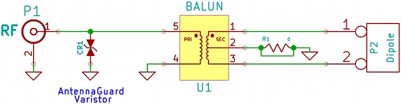
The new balun has the same schematic as the previous one:
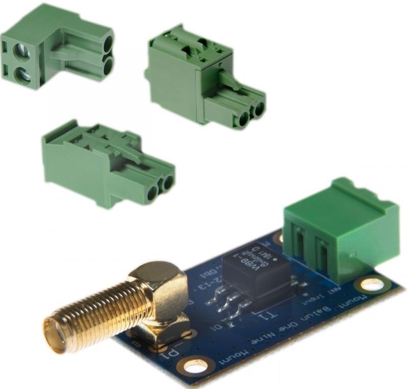
But it is slightly bigger, has a better connector for the antenna wires and (according to NooElec) uses a transformer which allows the tiny balun to work more efficiently from 0 to around 70 MHz (check out the charts found in the downloads section of this link).
The transformer used, judging from the pics, is a CoilCraft WB9-1, whose data can be found here:
https://www.coilcraft.com/wb_th.cfm
As I wrote the reason for this was the fact that a friend of mine reported that he used the (v1) balun with a Loop On Ground (LoG) Antenna !
If you look at the schematic (above) you’ll notice that there’s a “jumper” labeled R1 (zero Ohm resistor). That tiny detail is important, see, leaving the balun as is, it will work fine with a longwire, one just connects contact #1 to the antenna and #2 to a counterpoise or ground system and there he goes, BUT there’s another way to use the balun, that is, CUT the “jumper” (ok, resistor) labeled “R1”. If you cut it, the balun will become a 9:1 isolation transformer and with such a modification will work just fine with the KK5JY “LoG”
antenna: http://www.kk5jy.net/LoG/According to what my friend reported, the balun works just fine, and although probably the ferrite core used in the V1 isn’t up to par with the original one used by KK5JY, the difference isn’t so huge.
Oh, and I also suspect that the modified balun may work fine with the KK5JY simpler passive loop http://www.kk5jy.net/rx-loop/ which may be a nice antenna for restricted spaces!
I think it may be of interest to people not knowing/willing to wind their own baluns, at that point one may just need an enclosure to protect the balun and putting up a receive antenna will be as easy as 1-2-3.
Thank you for sharing this! Readers: Grayhat has been encouraging me to deploy a LoG antenna at my home and I do plan to do so in the coming months. Please comment if you use a LoG similar to the KK5JY model and what your results have been.
Thank you again for the tip, Grayhat!
I’m confused why we are calling a Loop on the Ground unbalanced. Aren’t loops inherently balanced?
So if my research is correct the V1 version of the NooElec Balun is by default a Bal-un and a 9:1 isolation transformer, and should be used with a balanced antenna such as a Dipole unless the R1 lead is broken/cut on the board. At that point it can it be used with a unbalanced antenna like a random length wire or a “LOG” antenna. if the R1 lead is cut at that point the V1 version is a UN-UN
But the V2 by default is just a 9:1 isolation transformer and an un-un, and does not need any lead cut or modifications to use with a random wire/”LOG” setup.
Is that a correct assumption?
Thanks,
If using this for a Loop on Ground (LOG), how do you connect the wires, one to each terminal?
Hi,
Will be using with a new SDRPlay RSPdx.
Inputs on the RSPdx are apparently now all 50 ohm.
So, i guess, something like the cheap NooElec 9:1 Baluns will be required.
Question: For a longwire receive only going to one of the terminals, should
the other unused one be left floating, or grounded ? Why ?
Same answer for the new Version 2 they have ?
Worth getting over the original one which I have ?
Or, are there “better” choices, but still relatively inexpensive ? Why ?
Thanks,
Bob
Hi Bob, didn’t notice the post (apparently the blog doesn’t send notices if someone posts a comment)
As for the NooElec; start by looking at the schematic
https://www.nooelec.com/store/downloads/dl/file/id/40/balun_one_nine_schematic.jpg
now, if you carefully look at it, you’ll see that, as it’s shipped, the device is configured as a BalUN, so it can be used with balanced antennas (e.g. a dipole) feeded by an unbalanced line (coax), willing to use it for a longwire, you’ll need to cut the “R1” which is basically a “jumper”, you’ll find it on the back of the PCB, use a cutter to cut it and you’ll obtain an UnUn (unbalanced to unbalanced), now, connect the longwire to one of the clips and connect the other to either a ground rod using a short run of wire or a counterpoise (which may be a shorter run of wire just laying on the ground)
Willing to use the device for a balanced antenna, you may just solder a jumper (or avoid cutting the R1), and connect the antenna wires to the clips, such a configuration may also be useful if you use a ladder line to feed your balanced antenna, in such a case you may connect the balun to the end of the ladder line and the coax to the balun connector
Getting back to the longwire, notice that it length isn’t exactly “random”, there are some caveats, so if you’re going to set up one of them, my suggestion is to carefully read this
http://www.hamuniverse.com/randomwireantennalengths.html
and pick one of the recommended lengths which fits your available space; not really so important for an RX-only antenna, but for sure won’t hurt 🙂
Also, and since we’re at it, a longwire is a cheap and easy antenna, but it isn’t exactly a “quiet” one, so it will pull in quite a lot of noise, willing a quieter (not deaf !) antenna, you may consider building the “LoG” (http://www.kk5jy.net/LoG/) which will still only require some length of insulated wire, but which, in my experience, will be quieter than the longwire and allow you to “pull” a lot more stations out from the noise 😉
Forgot, for further informations about the balun, also see the “user reviews” section here
https://www.amazon.com/NooElec-Balun-One-Nine-Applications/dp/B00R09WHT6
HTH
Something doesn’t make sense about the pics, schematic, & description.
From the pic above & on the nooelec site, it’s clearly a WB9-1 transformer – except that, according to Coilcraft’s datasheet (and the through-hole WB9-1L i’ve got here & just tested), neither side is centre-tapped. Coilcraft in fact don’t list a centre-tapped 9:1 in the WB series; the closest would be the 8:1 WB8-1TL or TSL.
Maybe it’s a custom transformer – though Coilcraft usually mark those differently. Wonder if Nooelec originally designed their board for something like a Minicircuits ADT9-1T+ – which is centre-tapped on the high-impedance side – then changed transformers without checking?
Grayhat &/or his friend might like to check whether the CT pin connects to either side of that winding. It’ll be interesting to see if it does.
And … re-reading now, I see that the description & circuit refers to the older v1 balun, which /does/ use what looks like a Minicircuits TC-series centre-tapped balun. Should’ve read more carefully!
If you check the back side of the v2 board (image on nooelec website) you’ll see that the center tap is grounded through a resistor marked as R1 and given that both the v1 and v2 share the same schematic, my guess is that the board in the pic may be some pre-production unit
I stand corrected
https://www.rtl-sdr.com/testing-version-two-of-the-nooelec-balun-one-nine/
looks like the v2 does use a wb9-1, in such a case the “r1” makes no sense; at any rate that would mean that the v2 as is will be an isolation transformer so it will work w/o modifications with the LoG antenna
Ok got one in my hands, there is no mounted R1 and the transformer is a coilcraft wb9-1 which has no center tap on the high-z side so the v2 is ok as shipped for use with a LoG antenna, at least on HF, since the “wideband transformer” (which it is) is only efficient between 0.1 and 100 MHz, outside that range efficiency drops with steep curves (see the datasheet) so it’s ok for an HF (160 to 20 meters bands) “Loop on Ground” but not so ok willing to use the LoG for lower frequencies