
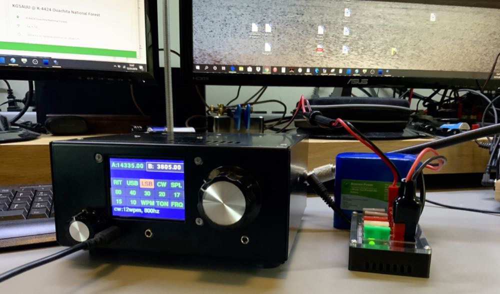
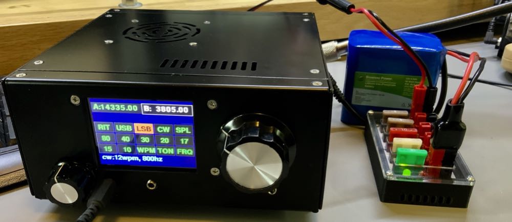
Last Friday, after returning from holiday travel, I found a belated Christmas gift on my doorstep: the new uBITX V6 QRP transceiver.
In the spirit of full disclosure, this package wasn’t delivered by Santa, rather by DHL in record time from India. As I mentioned in a previous post, I simply couldn’t resist purchasing such an affordable general coverage transceiver.
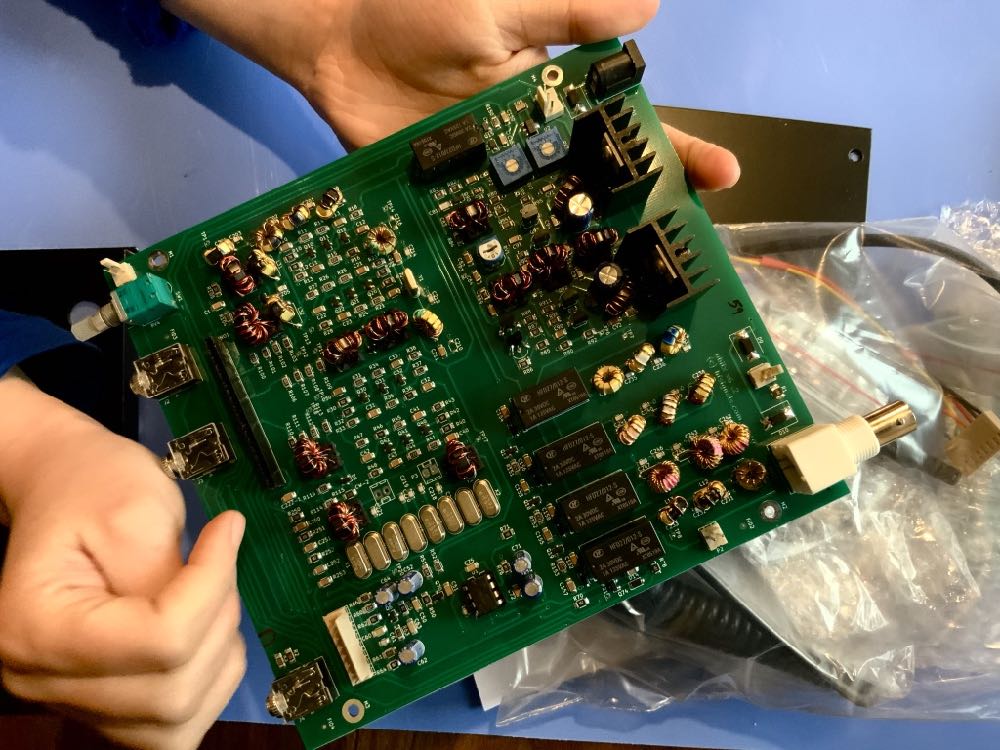
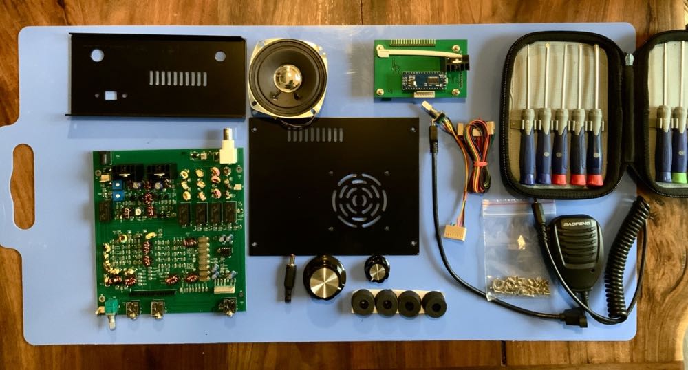
To be clear, the uBITX V6 isn’t really a kit. The boards are all fully populated by a women’s cooperative in India. You can purchase the uBITX V6 for $149 without a chassis and for $199 with a custom metal chassis. I purchased the latter.
Assembly may take thirty to forty minutes following HF Signals’ online guide. I employed my twelve year old daughters who pretty much assembled the entire radio–I only helped seat the display to the main board.
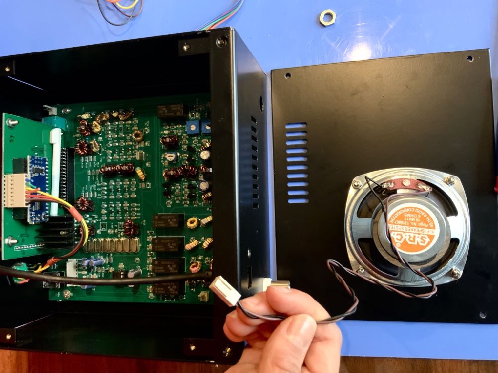
There is no firmware or software to upload. Simply assemble the radio, solder a power cord to the supplied coaxial plug (hint: positive tip polarity), connect an antenna, connect a power supply, and turn it on.
You’re on the air!
So far, I’ve only scanned the bands and listened to QSOs and broadcasters (no AM mode, so I’ve been zero-beating stations in SSB). Today, I hope to chase a few parks via the Parks On The Air program.
I still need to calibrate the radio yet (although it does zero beat WWV perfectly).
If you purchase the uBITX V6, don’t expect a benchmark transceiver. This uBITX V6 feels more like a work-in-progress and I assume the pre-loaded firmware is simply a first iteration.
Since the radio is open source, I expect hams will soon hack this rig to go above and beyond its basic (understatement alert–!) feature set.
If you’re a CW operator, you might hold off on purchasing until someone has properly implemented the mode. I made some test CW CQs into a dummy load just to check out the keyer and I honestly don’t think I could manage a proper QSO at this point. Sending is sluggish and…well…awkward.
Note that I will be writing a full review of the uBITX V6 for a future issue of Radcom (the RSGB’s monthly publication). Check back here for uBITX V6 notes along the way.
Also check out the excellent blog of our friend, John Harper (AE5X), who has also recently put the uBITX V6 on the air!
Anyone else order a uBITX V6? Please comment!
Do you enjoy the SWLing Post?
Please consider supporting us via Patreon or our Coffee Fund!
Your support makes articles like this one possible. Thank you!

Hi all,
I am looking forward to reading any serious review of CW operation. Nothing found on YT, nothing found on any forum. As it has no real BPF’s in FE, 15k wide roofing, no narrow 2nd IF xtal filter in CW mode and I read several complaints about the keying and pump key usage > it looks like it is real nightmare to operate on CW. Any experiences there pls?
73 – Petr, OK1RP
It does not appear to be suited for serious cw as the IF is clearly too wide
Without serious redesign it really is a non-starter.
G7VFY
Have you done a SOTA or POTA activation with your Bitx6.1?
regards
G7VFY
Great idea! I haven’t yet, but I certainly will.
Cheers,
Thomas
K4SWL
My version 6 went together pretty well, but here are a couple of issues I have not seen addressed elsewhere:
(a) the list of parts included was mostly very nice. But their reference to “boots” for the rubber feet was confusing to me, a USA-English speaker
(b) On mine, at least, the screws holding the front and back panels were already installed on one end (front as I recall) but not on the other. I had to remove a panel in order to mount the main PC board without damaging something, Of course I did that before noticing that one panel was all set to come off because it did not yet have the screws, and I chose the other one.
(c) The most critical one: The Raduino mounts to the front panel with four small screws. Those go through the panel into one end of four hexagonal brass spacers, that have female threads at that front end. BUT: The other ends of those spacers, with male threads, goes through the Raduino PC board, and there are four nuts there. On mine those nuts were loose, although I did not notice it until I had already plugged in the Raduino board. (One was so loose that it was about to fall off.) Stubbornly I tightened the nuts with the board in place. That was a bad idea! The two nuts at the top are easily enough grasped with small pliers, although those are not too convenient for tightening because of the nearby components you don’t want to damage. But the lower nuts are not easy to reach, and the one on the right (viewed from front of radio) can’t even be seen because it is underneath the heatsinks on the board. Trying to tighten those with pliers risks damage to components on the main board, in particular the toroids right under that hardest to reach nut. So for safety sake you really want to use a small socket to tighten these nuts. I had a 5mm socket: I haven’t measured them, but the nuts seem to be slightly larger than 5mm and smaller than 6mm. (5.5mm?) I managed to use the 5mm socket: The nuts are slightly chamfered and while the socket would not fit down over the nut properly it would go over the resulting taper enough to do the job.
BUT: The best/safest thing to do would be to make sure those nuts are tightened down before plugging in the Raduino board, while the nuts are still easily accessed.
(One could try to tighten the front screws enough that they turn the spacers, tightening the nuts. But the screws went in so easily that they pulled the PC board up tightly against the front panel immediately, and would not turn the spacers.)
WA9D
Hi Bob
Standard for Metric 3 (M3) is a 5,5 mm nut
Built the TRX also
Works great for this prize
73 Adrian
PE1DCL
Hi,
Just assembled my ubitx v6.1.There was nothing to it,just mount the board and controls and nothing to solder.I was very disappointed after powering it up to see the screen light up and nothing there,a blank white screen. I opened the case and checked to make sure the the pins were aligned and they were.I am able to hear signals when rotating the encoder but screen is blank.I tried holding encoder knob in while powering up (for menu)but still nothing.Tried to find some information online but nothing for this problem with no luck.I’m thinking the the raduion was not programed properly or not at all.Any suggestions would be much appreciated.
Thanks
Ken
Hi, Ken,
It sounds to me like the Arduino Nano didn’t have the code properly loaded.
I, too, got a blank screen at one point, but it wasn’t white–rather, the screen was blacked or grayed-out yet still backlit. After re-compiling the code and trying to upload it once again, it still didn’t work. After a little troubleshooting, I could see that the Arduino Nano was working, but not part of the Raduino board. uBITX confirmed this and sent me a replacement Raduino board. Somehow, mine got fried.
It was with this uBITX that I learned how to download, compile and upload code to the Arduino Nano. I wish I could explain the process, but I’m still so new to it myself.
You should try to re-upload v6.1 to the Arduino. I’m guessing that might solve your problem. If not, you might contact uBITX support.
Cheers,
Thomas
There is a robust discussion group that you should peruse because it will help you solve some of those issues you mentioned. https://groups.io/g/BITX20
Thanks for sharing this!
Thomas thanks for the initial evaluation. You mentioned using a keyer; have you tried it with a straight key?
Thanks and Happy New Year.
I have. It need almost a full character formed before it actually starts sending. It’s a little strange. I’m sure it’s a timing thing that can be sorted out, no doubt. It is a fun little radio–been using it most of the day.
Cheers,
Thomas
I’m looking forward to reading your review in RadCom when it falls in on the front door mat.
de G8AUU, SO6AUU/9