
 Many thanks to SWLing Post contributor, Brian, who writes with the following inquiry:
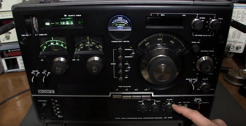
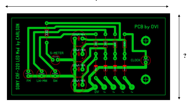
I found a pic of a printed circuit board, based on Mr. Carlson’s Sony CRF-320 panel light mod, on the Yahoo 320/330 fan page but no board dimensions or component values.
I plan to order a bunch of these so if anyone can sort out some measurements on this board or are interested in obtaining a board, please comment. I am a novice in this and am unsure of the component values. I have wired up an electric guitar, so this I anticipate will be less complicated.
Post readers: If you can help Brian with this info, please feel free to comment!
I’m looking for a manual for the Sony CRF-320K it is called Measurments & Adjustment’s. Would of came out in 1977 or 1978. I see it on Worthpoint but can’t seem to be able to purchase it. Any one got ideas on how to get this Manual?
I don’t know if it was just luck? I bought a Sony CRF-330K Shortwave Radio with Cassette Tape Deck. It has no scratches anywhere on it. It was used barely 1 month. The Original Owner spent $500.00 to get it up and Running like new. I have all the Original Manuals & Paperwork & bought all the Original Sony Optional Accessories for it. It even has the Sony Factory Stickers on it & all the Throw in Cards. It was Originally released in Europe by the Back Plate. Not even a rust spot on it. I give it a 10 star rating.
Hi.
Distance between LED leads is 17 pixels, in a actual LED is 2.5 mm (0.147 mm/pixel)
LED diameter is 33 pixels, in a actual LED, may be 3 mm or 5 mm. Only 5 mm fits with your board (0,152 mm/pixel). And so on. My best fit is 0.151 mm/pixel, and I do use in results.
Results:
LED: Lead Pitch = 2.5 mm Diameter = 5 mm
Capacitor: Lead Pitch = 4 mm Diameter = 8 mm
Resistor: 0.25 W = 1/4 W will be ok
Diodes: 1N4148 will be ok
Board-Width (Horizontal) = 85 mm
Board-Width (Vertical) = 45 mm
Please remember: My results may be wrong. Better if there are other people with the same results.
—————————————————————————————————-
Your components (resistor, diodes, leds and capacitors) are widely available in every local electronics shop. If you wish see products and specs, see on uk.rs-online.com:
*** LEDs ***
Display et Optoelectronics > LEDs et LED Accesories > LED
Left-Panel:
Mounting-Type = Through Hole
Package-Type = 5 mm (T-1 3/4) (Lead Pitch=2,5 mm)
I do recommend: Led Colours green, red, yellow, or Forward-Voltage between 1,6 V and 2,2V, but it depends on input voltages.
Examples:
https://uk.rs-online.com/web/p/leds/2285988/
https://uk.rs-online.com/web/p/leds/2286004/
https://uk.rs-online.com/web/p/leds/2286010/
*** Resistors ***
Passive Components > Fixed Resistors > Through Hole Fixed Resistors
Left-Panel:
Resistance = 330 Ohm (Ohm = Omega)
Power Rating = 1/4 W = 0.25 W
Example:
https://uk.rs-online.com/web/p/through-hole-fixed-resistors/7077622/
*** Capacitors (Electrolytic) ***
Products > Passive Components > Capacitors > Aluminium Capacitors
Left-Pannel:
Capacitance = 220 uF (u = micro = greek “mu”)
Voltage = 16 V
Mounting-Type = Through Hole
Lead Pitch = 3,5 mm
Don’t choose axial-type (two wires opposite). Choose radial-type.
Examples:
https://uk.rs-online.com/web/p/aluminium-capacitors/4758832/ (Lead Pitch = 3.5 mm Diameter = 8 mm)
https://uk.rs-online.com/web/p/aluminium-capacitors/7110949/ (Lead Pitch = 3.5 mm Diameter = 8 mm)
*** Diode ***
Semiconductors > Discrete Semiconductors > Switching Diodes
Left-Pannel:
Mounting-Type = Through Hole
Maximum Forward Current = must be over 100 mA (a LED needs 20-30 mA)
I recommend 1N4148, because is a standard, is widely available, and exceeds your needs.
Example:
https://uk.rs-online.com/web/p/switching-diodes/7390290/
————————————————————————————————–
Board circuit is so simple…but I don’t understand why there are two LEDs, S-meter and clock, with
the same function. These two LEDs do the same thing, same light, same function. I don’t understand
why “clock” = “S-meter”.
Warning: Diodes, LED and Electrolytic Capacitors have plus and minus leads. Don’t mistaken.
Shouldn’t be hard to figure out using standard component pin spacings, drill hole diameters, etc. For example, typical through-hole LED lead spacing is 2.54mm. Resistor and capacitor values are marked right on the picture; LED & diode designations aren’t quite readable, but it’s unlikely that they’ll will be critical or anything other than standard TH LEDs & small signal / LV rectifier diodes.
I will point out that I understand that, at least in the US, board designs like that are copyright, and Mr Carlson provides access to his designs to Patreon subscribers only. Some would consider wholesale copying of his design “ripping him off”.