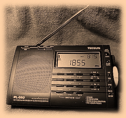
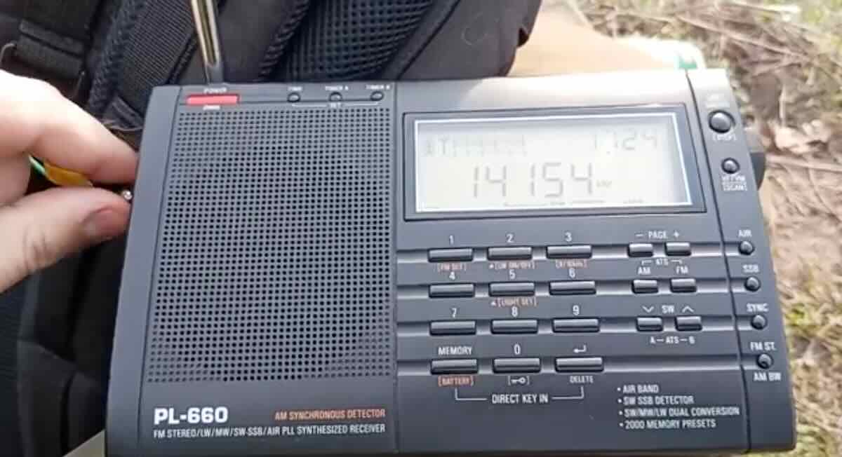
My original PL-660 has high mileage but still
has its original kick stand and whip antenna.
The Last Radio I Really Needed
By Bob Colegrove
Like most folks, I have a favorite radio. My favorite radio is the one I happen to be listening to at the time. Each radio has its own attractions. The fact that one particular radio is turned on indicates that, at least for the moment, it is my favorite.
I also have a special radio. It is special because, ever since I bought it, there has never been a compelling reason to buy another radio. That said, there is no accounting for irrational behavior which has subsequently caused me to buy several more radios, always with the hope that the next radio would somehow provide better performance than my special radio.
My longstanding experience has been with vacuum tube radios. I have used multiband radio consoles. I have used everything from a Hallicrafters S-38 to a Collins R-390A and most everything in between. I tried a couple of analog, multiband, solid-state portables in the 1960s and ‘70s. I bought a Sony ICF-2010 early on and still have two of them fully functional. For many years, the -2010s were my go-to radios.
Then, I happened to read the review of the Tecsun PL-660 in the 2012 WRTH. The price seemed reasonable, and I decided to buy one. From the very beginning, I was not disappointed. Selectable sidebands and synchronous detection – not a Sony, but very good. Further, the -660 was notably smaller and packed quite easily. I could include a pair of earphones, a length of wire and this radio, set up away from the shack, and operate.
So why is this radio special? It is not perfect. But for LW, MW, SW, and FM, there is nothing I can hear on any of my radios that I can’t hear on the Tecsun PL-660. Reception seems to be especially sensitive and clear.
I must qualify the claim above. Normally I use external antennas. External antennas are the great equalizers. Properly matched they make a radio perform at its best. Radio reviews and comparisons will often include judgements about sensitivity. Unfortunately, many reviewers do not specify the conditions under which they tested the radio. The reader must assume that these judgements are based on the use of stock internal antennas — most often the LW and MW ferrite loop and the SW and FM whip. For portable radios this makes sense, as internal antennas are paramount to the radio’s transportable versatility.
Not Perfect
I will spare everyone yet another review of a radio now in its adolescent years. I merely focus on a couple of picks I have with the PL-660. There are others which are well documented.
Birdies
Probably the worst fault with the -660 is birdies. There are a few along the LW spectrum but the worst by far is one which generally appears between 950 kHz and 1000 kHz in the MW band. I have read where this is traceable to the DC-DC converter but have never found a remedy. This nasty signal is very rich in harmonics and will replicate through the entire SW spectrum. Further, the fundamental birdie and its harmonics tend to slowly drift upward for about an hour after the radio is turned on. The drift accelerates with multiples of harmonics. For example, while the fundamental birdie is creeping up 1 kHz, the second harmonic will travel 2 kHz, the third 3 kHz, and so forth. There are many harmonics where no harm is done; however, the 4th harmonic will blaze a trail squarely through the 80-meter ham band. Wait a while and it will drift onward but ultimately stop at some equally inconvenient location.
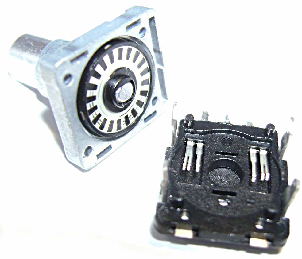
Poor Encoder
The PL-660 tuning encoder, as with its cousins in the -600 and the -680, is … well, very poor. From the get-go it will jump erratically forward or backward. This becomes worse over time, particularly with any prolonged periods of disuse. I have not determined whether this is dirt, poor contact, or just poor design. I have found that vigorous exercise forward and backward with the tuning knob is the best temporary remedy. This will generally bring the encoder back to tolerable performance.
Replacement encoders are available at modest cost. I went this route as a last resort but managed to lay up my -660 for several months having failed to make the replacement work at all on the first attempt. A few months later with renewed determination, followed by a series of deep cleansing breaths, I reopened the radio and discovered that my mistake was just a solder bridge between two of the encoder pins. Note to self: For the future, this surgery should only be performed by people with good vision and steady hands. After several months of storage there was unbounded joy when the 12-year-old -660 came alive and began to tune perfectly – well as perfectly as it could.
My Mods
One of the reasons why the Tecsun PL-660 is special to me is that it is a tangible link to my tinkering past. In former times, much satisfaction was obtained by aligning RF and IF stages, restringing dial cords, and replacing leaky capacitors. For most tinkers, the advent of large-scale, solid-state integration and surface-mounted components has made tinkering virtually impossible. Detailed data are scarce, parts much more specialized, and soldering skills more demanding.
The PL-660 came along at a point where vacuum tube tinkering was still within recent memory and the skills for maintaining and modifying high-tech radios had not become so intimidating. To summarize, with just a few exceptions, today’s radios are for all practical purposes unrepairable, unmodifiable, and therefore more readily disposable. What a pity. The term “parted out” has entered our vocabulary, whereby a defective radio is cannibalized to provide its serviceable vital organs to its remaining siblings.
Dynamic Squelch
Briefly, the Tecsun PL-660 dynamic squelch function automatically adjusts the signal threshold based on its strength. Ostensibly, this helps prevent the radio from being overwhelmed by noise when no signal is present while still allowing strong signals to be heard. The “dynamic” part of the term refers to the feature turning itself on or off as the situation demands. The downside is twofold: a) weak signals may be totally blocked with squelch engaged; and b) the feature may oscillate on an off as a signal fades and then gets stronger. There are several demonstrations of this on YouTube.
In 2012, a Russian radiofile managed to identify the transistor that switched the feature on and off. By the simple expedient of grounding one of its leads, it could be permanently turned off, eliminating its drawbacks. An optional further modification provided for the tone control switch to be repurposed to manually enable or disable the basic modification.
The relatively simple concept turned out to be rather involved surgery requiring a large metal circuit shield to be unsoldered and removed to access the transistor. The old Yahoo PL-660 Group was abuzz with interest at the time. Many folks were doing the modification. Had it not been discussed so widely, I would likely have ignored it. But being a wild, impulsive 70-year-old at the time, I had to give it a go and fortunately was successful.
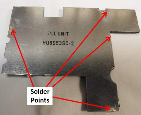
Disablement of the dynamic squelch required removal of a shield on PCB
External LW and MW antennas
I do not like to be limited by the lack of an external LW/MW antenna connection. The PL-660 has no means to switch one on. You can easily inductively couple an AN-100/200 or Terk Advantage loop and get good results, but I wanted more. I took the classic approach of winding a 5-turn transfer coil around the ferrite bar. Initially I simply connected this to a twisted pair which ran out the unused hole for the wrist strap. The twisted pair was connected to a phone jack and dangled out of the radio like a pig tail.
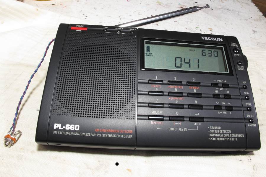
Pigtail used the hole in the case vacated by the wrist strap.
Sometime after my mod, Geir Laastad, LA6LU, published a paper with a much more elegant solution. He discovered that the PL-880 used a stereo external antenna jack, the center (ring) terminal was not used, and the cumbersome pigtail could be eliminated by connecting the added transfer coil between this center terminal on the jack and the radio ground. This necessitated use of a stereo plug to mate with the jack for connection of a LW/MW external antenna, but the jack could otherwise be used normally for SW. I found that Tecsun used the same stereo jack approach on the -600, -660, and -680, and was able to connect the transfer coil to each radio the same way. Geir’s paper is at https://groups.io/g/Tecsun-PL-880/files/_Tecsun_PL-880_LW_&_MW_Antenna_Mod.pdf, but you may have to request membership in the group to download it.
Enlarged fine tuning knob
One of the weak features of the -600, -660 and -680 is the fine-tuning pot. Zero-beating a signal is a bit touchy. The problem is exacerbated by a mechanical detent in the control’s center of rotation, that is, the point where zero beat is likely to be encountered. I found a foam, doughnut-shaped packing spacer from a spindle of CDs had just the right internal and external diameters to slip over the fine-tuning knob and provide some added gear reduction. By pressing the foam against the case, the effects of the detent could be mitigated.
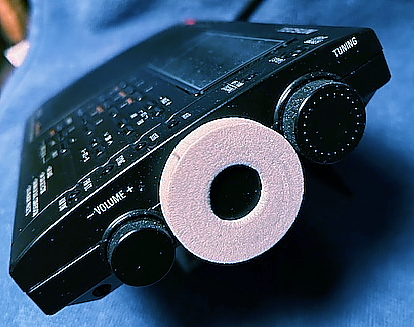 Well, unfortunately, CDs are going the way of cassette tapes these days, so the availability of the packing spacers may not be so good. It may be within the realm of possibility to fabricate one.
Wrist Strap
My final alteration is not so much a modification as it is a simple omission. On the first disassembly of the -660 I omitted reinstalling the wrist strap. IMHO, this piece of ribbon is no more useful than fender skirts on a ’57 Chevy. Besides, it’s usually in the way. Sometime in the murky past, this appendage made its appearance on a small portable radio. Since then, nearly every manufacturer has felt compelled to include one. I envision someone grabbing the radio by the strap and sashaying down the street with it dangling precariously by one’s side. I have tried to imagine how its purpose might be inverted into a safety feature – perhaps first looping the strap around the wrist and then grabbing the radio with the hand. But somehow, I can’t imagine anyone going to that trouble. Maybe I’m missing something.
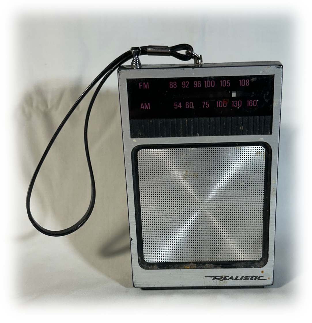
The wrist strap on this Realistic 12-714 AM/FM pocket radio from 1984 is hard to ignore.
The reader may be aware of other modifications to the PL-660, but mine are limited to those described above.
Epilogue
The old -660 has never been coddled. Neither has it been subjected to the same vicissitudes as a soccer ball. It remains a relatively handsome, finely crafted instrument still capable of soldiering on in the frontlines of the DX battle.
Is my old PL-660 a better-than-average “creampuff” off the Tecsun production line? Does that make it special? During the three or four months it was laid up with the encoder problem, I took the precaution of buying one of the last production units – this on the chance it might be my only opportunity of having an operational PL-660. The newer one looks like its predecessor; it operates like its predecessor, even to the extent that it has the same birdies and the erratic encoder. It does have the added feature of dial recalibration – a feature totally unnecessary on the original PL-660. Somehow, it’s just not the old PL-660. That one is special.
Maybe you have a special radio.

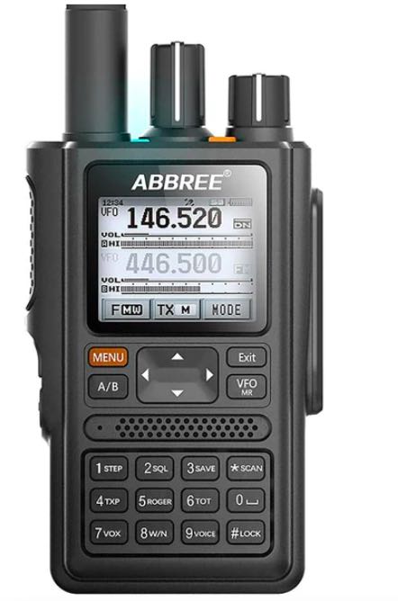
 Many thanks to SWLing Post contributor, Vladimir, who writes with a tip: