Tag Archives: Yaesu FRG-7 Mods

Kostas improves the contrast on his FRG-7 digital display

Many thanks to SWLing Post contributor, Kostas (SV3ORA), for sharing the following guest post which originally appeared on his radio website:


FRG-7 digital display contrast improvement

by Kostas (SV3ORA)

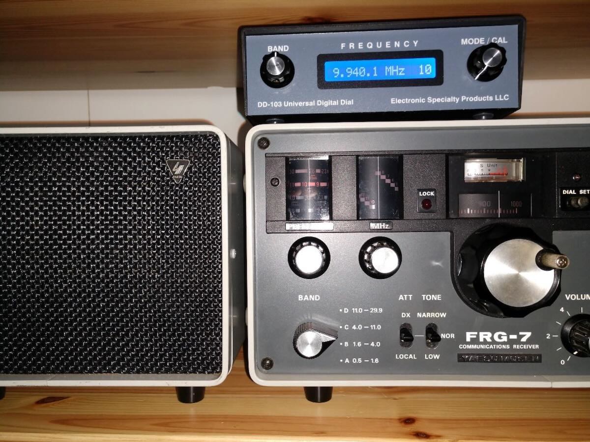
The FRG-7 digital by Marcel Jacobs PA8MA, is a very well thought modification KIT for the Yaesu FRG-7 receiver. It really adds to it one of the things it misses (and it misses a lot) to become a more “serious” receiver in the modern era, the digital frequency readout and S-meter. If you are like me and enjoy classic radio gear, but you do not want to compromise much the every-day usability, I recommend you this KIT. I have to say here that, the first thing you would want to do if you use the receiver for SSB, is to perform my SSB-related mods as well.

When I installed this KIT on my FRG-7 The first thing I did not like about it, was the very bright display which blasts your eyes with light especially at night on a low-lit shack. Not only that, but your eye will condinuously focus on the bright display and you loose the magic of the rest of the radio controls and displays. I wanted the digital display to be one of the parts of the radio and not the major thing that my eyes will look all the time. Marcel was smart enough to include 2 brightness levels in software. The low brightness setting does not actually change the backlight of the display, it just changes the graphics in more dim colors. As a result in either setting, the backlight color is very bright and this decreases contrast a lot. The background of the numbers in the display has a blue-ish color and not true black. Not only that, but the edges of the display, are visible too. I have solved all of these problems with a simple modification to the KIT.

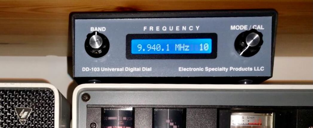
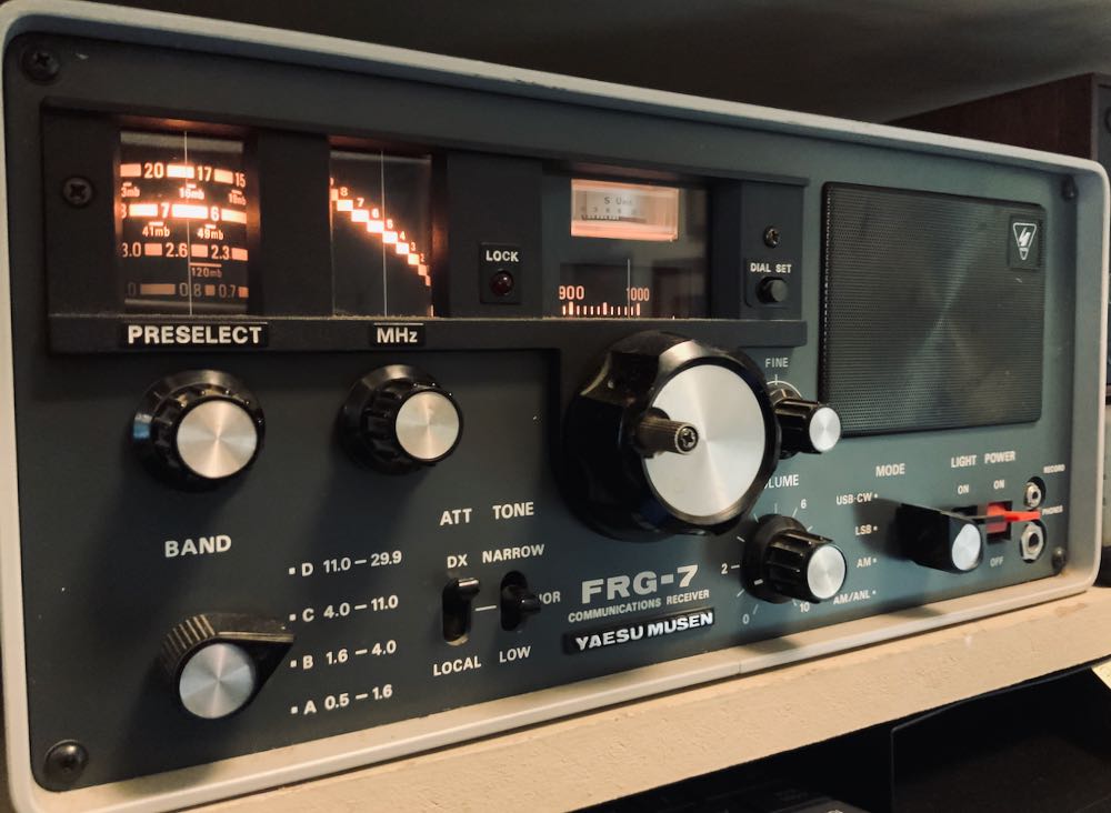
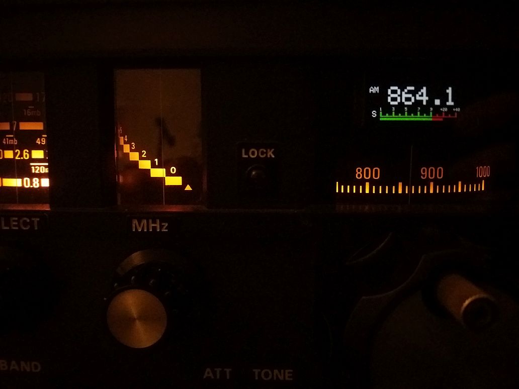
The picture above, shows the display after my modification. The picture is taken on a dim-lit shack using my phone, with no further image processing. What you see in this picture, is exactly what it looks in reality, after my modification. Notice how the background of the display, remains pure black and the numbers and graphics of the display do not blind you anymore and are of the same brightness as the rest of the original backlit graphics of the radio. This allows your eye to wander around to the rest of the nice radio backlit things, without focusing all the time on a bright display. This is very relaxing to the eye and the brain as you scan for stations. You actually only look at the digital display when you want more accuracy. Compare this nice display contrast with the one presented on Marcel’s manual and you will notice the difference.

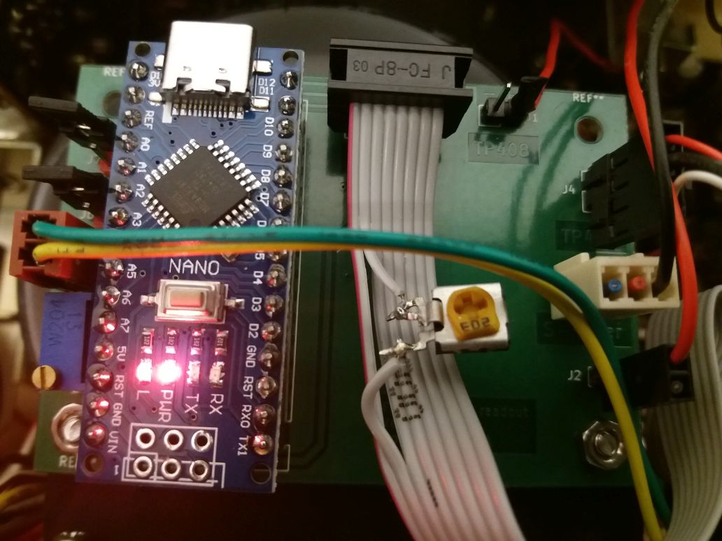
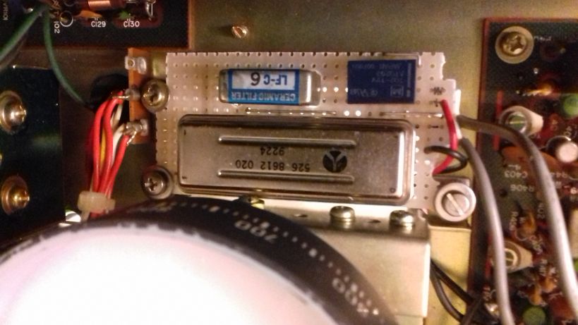
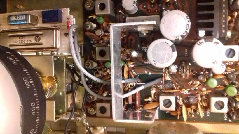
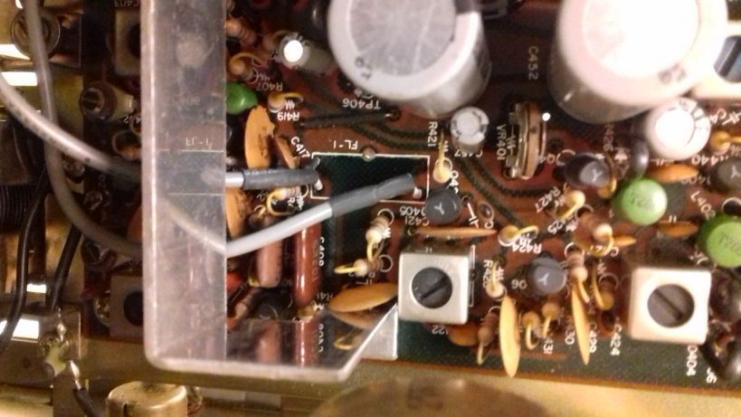
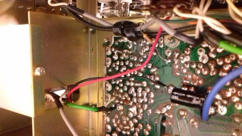
The modification is really simple and it does not need a schematic. It is just a 22k potentiometer, connected as a variable resistor like shown in the picture. I just cut the second cable (from the left), of the ribbon and then soldered the variable resistor there. That’s it. Depended on the light conditions in which you operate the receiver and on your personal preference, you can set the brighness from full to very dim. In the software setting, set the brightness to maximum. Then use this variable resistor to decrease it to your desired level.

Spread the radio love

Guest Post: Review of the Electronic Specialty Products – Model DD-103 Universal Digital Dial

Many thanks to SWLing Post contributor, Bob Butterfield, who shares the following guest post:


Review of the Electronic Specialty Products – Model DD-103 Universal Digital Dial

by Bob Butterfield

I recently brought out of storage my Yaesu FRG-7 Communications Receiver to use “in the shack” once again.  I have always regarded the FRG-7 as a capable receiver but just did not have space as my radios co-exist with part of my daughter’s over-flowing stuffed animal collection–among other things.  After a couple of dozen members of the plush collection were relocated, I now had room for another receiver!  I checked the FRG-7 out carefully and found everything was functioning well, except for a modification I made decades ago which was the installation of a 100 kHz crystal calibrator kit inside the receiver.

I am the original owner of this FRG-7 which is an early production unit (the one without the small fine tuning knob).  I had always desired an external digital frequency display for this radio and thought now is the time.  I did some research, visited various radio forums, and decided on purchasing an Electronic Specialty Products (ESP), Model DD-103 Universal Digital Dial.  This unit is not cheap, US$140, plus $15 shipping, but seemed to fit my needs.  If technically inclined, one could possibly build an external display for themselves at lower cost.  What may be of interest to many concerning the DD-103 unit is that it comes pre-programmed for dozens of transceivers and receivers (to include the FRG-7).  Plus, if your radio is not pre-programmed it can be set up manually.

The DD-103 is an attractive compact external unit measuring 2”H x 6”W x 4”D with a very easy to read backlighted LCD (white on blue).  The unit comes with connecting cables, U.S.-type power supply, and instruction manual.  In my opinion, despite its size, this is one solid and well-built unit.  As per the ESP web site, new units are not stocked but are assembled upon order.  After ordering I immediately emailed ESP with my receiver make and model (I would recommend this for all buyers).  My unit arrived in a little over two weeks and I received a separate sheet accompanying the unit with specific instructions for my receiver.  Hook up was a breeze.  All that was needed was to set a few DIP switches, connect one lead to the indicated test point on the identified board, and the other lead to chassis ground (alligator clip leads are provided).  The connection to the display is made with the included RCA cable.  I made one simple installation modification, installing a RCA female/RCA female bulkhead connector on the rear panel of the FRG-7 to allow for quick disconnect.

The DD-103 display is programmed into 1 MHz increments.  To operate, you select the MHz range you want (for example 9 MHz) on the DD-103.  On the FRG-7, I then tune its pre-selector and the same desired MHz range, and finally tune in the frequency and watch the DD-103 display change accordingly.  The operational design of the DD-103 fits nicely with the Barlow-Wadley circuit design of the FRG-7.

A key feature of the DD-103 display is that it reads the entire frequency (e.g., 9.940.1 MHz) so you always know where you are with just one look.  In addition to AM mode the DD-103 can be further programmed for CW, LSB, and USB modes, as well as 10 Hz or 100 Hz resolution.  As stated in the unit’s manual, it can also be calibrated on each frequency range so as to correct IF amplifiers that are a little off or errors associated with aging receiver crystals, if applicable.

It is nice to have my FRG-7 up and running again and utilizing the new external numeric frequency readout.  Truthfully, I have been reminded just how good the FRG-7 is.  Though it does not have as many features, it holds its own when put up against my other classic receivers (JRC NRD-545, JRC NRD-535D, and ICOM R-75).

I must say I am quite happy with the Electronic Specialty Products DD-103.  The unit has good accuracy and stability as it utilizes a TCXO reference oscillator.  If I had to nit-pick about anything, I would likely point out that the on/off switch is on the back of the unit.  If your radio is in a confined space this possibly could cause operational issues for you.  Also realize that for the most part this unit is kind of a “one size fits all” package and it would not surprise me if certain receivers or transceivers might require lengthening of the connecting cable.  All in all this professional looking unit is a simple to use, simple to install, easy to read, designed well, and I think worth the cost.  For anyone else who is thinking about adding a digital frequency readout to a vintage radio, you may want to give this model due consideration.

Bob Butterfield

Photo of my FRG-7 with the DD-103 on top:

Web site for Electronic Specialty Products: http://www.electronicspecialtyproducts.com/dd103.html

Disclaimer: I have not been compensated in any manner in regards to this unsolicited review and purchased the DD-103 unit with my own funds.

Spread the radio love

How to install a mechanical SSB filter on the Yaesu FRG-7

Many thanks to SWLing Post contributor, Kostas (SV3ORA), for sharing the following guest post which originally appeared on his radio website:


How to install a mechanical SSB filter on the Yaesu FRG-7

by Kostas (SV3ORA)

The Yaesu FRG-7 is a general coverage MW/SW receiver that uses the Wadley Loop system for stabilizing the frequency tuning. The receiver has a good sound on AM mode, that reminds me the tube receivers sound. However, on sideband mode, it is pretty much useless. The IF ceramic filter that is used, does not have enough selectivity to reject the opposite sideband. No matter if the front panel mode selector switch states USB/CW and LSB, these just shift the BFO, nothing more. The receiver is a DSB set not SSB. A cheap way you can accomplish single signal sideband reception with the FRG-7 is described in this link. Whereas it works, it increases the audio bandwidth of the signals to the high pitch.

A better approach is to install an additional mechanical filter to the receiver. This of course requires expensive 455KHz mechanical filters, but if you have one in hand or if you are willing to pay for the improvement in performance, then this is the recommended option. But you can’t just desolder the ceramic filter of the receiver and solder a mechanical filter in place. On AM mode, you need wider bandwidth, but on SSB mode you need narrower. So both filters must be in place and a selection must be done in each mode. Thankfully, this modification is pretty easy on the FRG-7 and it does not require any modification of the external appearance of the radio.

The schematic of the FRG-7 is shown above. Everything with red color, are part of the modification. The modification is pretty straight forward. You have to desolder the original ceramic filter from the FRG-7 PCB and install it on a separate PCB along with the new 455KHz mechanical filter. To select between the two filters, a 9-12v DPDT relay can be used and it must be connected as shown in the schematic. The power for the relay coil is derived from one section of the mode switch (S3d). On USB or LSB modes, the BFO is energized and this power is also used to energize the relay, which in turn switches to the narrow mechanical filter on these modes.

A good place for the new PCB that accommodates the filters, is just below the main tuning dial of the receiver. There is a hole there and three screws, which can be used to also hold this PCB in place. I needed to replace these screws in mine with longer ones, because I used spacers to prevent the PCB from touching the chassis. But this is optional.

Two small pieces of coaxial cables are used to connect the new PCB to the pads of the ceramic filter, that has been now removed from the original PCB of the receiver. Ground these cables on both ends.

The power cables for the relay coil (shown with red and black in the picture above), are passed below the PCB to the chassis opening and through a hole to the bottom of the original PCB of the receiver. The ground wire is soldered to the filter ground point and the red wire is soldered to the mode selector switch S3d. S3d is the outer wafer onto the switch. Use a multimeter to find the contact of the switch that has VCC when the mode is switched to USB or LSB. This is the point where you want to connect the red wire.

After installing everything, you should perform an alignment of the TC404 and the T406 in the BFO section as described in the manual. This requires a frequency counter, but I did my alignment by simply adjusting the two controls by ear, until I got roughly the same pitch on LSB and SSB audio bandpass. These controls interact, so you have to do a bit of back and forth in both of them. It is very easy.

After installing the modification and aligning the receiver, the result is pretty obvious. No more DSB reception, SSB signals are received just once in the dial and their bandwidth is limited as it should on SSB. The mechanical filter I had, was a bit narrow (2.1KHz) so I can also hear a bit os “seashell” sound on SSB, but SSB voice signals are perfectly understood. It is interesting that the audio volume between the ceramic filter and the mechanical filter was just about the same, which indicates that there is no additional loss in the newly installed filter. Another interesting thing is that there was no need for any impedance matching using active devices or transformers on the mechanical filter. It worked just by directly connecting it. Neither it’s loss, not it’s response seems to be affected by any possible impedance mismatches.

Note that Collins produced both symmetrical and asymmetrical mechanical filters (yes they used two filters, one for USB and one for SSB in some of their gear). My filter is a symmetrical one (same roll-off response curve on both sides of the filter passband). If you use an asymmetrical filter, expect a bit different pitch when switching from LSB to USB and vice versa. Not a huge problem, but just a note.

By performing this simple modification, you will end up with an FRG-7 receiver that is trully selective, allowing for real SSB reception. Most importantly you do not ruin the appearance of your precious FRG-7, but just improving it’s performance. This modification would probably be appreciated much when deciding to sell your FRG-7 to someone else.


Thank you for sharing this practical and affordable project with us, Kostas!

Post Readers: Check out this project and numerous others on Kostas’ excellent website.

Spread the radio love

Kostas’ Yaesu FRG-7 adjustment that improves opposite sideband rejection

Many thanks to SWLing Post contributor, Kostas (SV3ORA), who shares the following video and writes:

In this 7.8Mb video (attached) is my solution for “converting” the Yaesu FRG-7 for single signal reception on SSB:

Not a mod actually, no additional filters, no soldering of any kind. Just tune the BFO on USB and on LSB a bit far away from the 455KHz ceramic filter (using the transformer for LSB and the capacitor for USB, as the manual states). As the video shows, this provides the near to
carrier selectivity to cut off the unwanted sideband.

The price you pay is more high frequencies (but in the wanted sideband) and a bit attenuated low frequencies as the filter is effectively shifted to higher frequencies. Very high frequencies cut-off is helped by the tone control of the receiver to some point.

This is a cost-free mod and requiring even no soldering skills, neither any mod to the receiver. Now as you tune the bands in SSB and CW, you do not hear the same signal twice. On AM mode nothing changes, since the BFO is switched off in this mode.

Many thanks for sharing this, Kostas! This seems like a simple adjustment for one of my all-time favorite receivers!

Post readers: Check out Kostas’ website for more modifications, ideas and radio projects.

Spread the radio love