Shortwave listening and everything radio including reviews, broadcasting, ham radio, field operation, DXing, maker kits, travel, emergency gear, events, and more
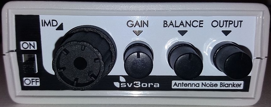
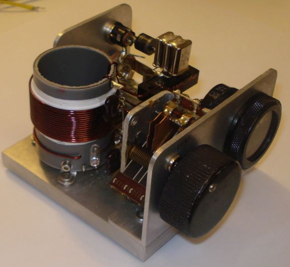
The NR-1, a revolutionary noise blanker that works directly on the antenna!
I designed my own noise blanker because:
I was tired of that HF noise that could not be beaten otherwise.
I wanted to remove it before it gets into my transceiver.
I could not install a separate “noise” antenna/coaxial for diversity.
I wanted to remove noise interference from any direction.
NR-1 is a revolutionary Noise Blanker which is the result of two-years of development and extensive testing by Kostas sv3ora.
NR-1 works directly at the antenna. This has significant advantages over the classic noise blankers which work at the intermediate stages of the receivers. It does not require a second “noise” antenna for its operation.
Furthermore, it is not based on cutting-off of amplifiers, unlike common noise blankers
do.
Because of these, the NR-1 is superior, compared tocommon internal Noise blankers of radios:
NR-1 removes noise before it even reaches the receiver. Thus, the front-end RF
stages of the receiver are unaffected by noise, unlike a common noise blanker
which removes the noise after it has first passed through the internal circuits
of the receiver.
NR-1 removes high-level, high-repetition-rate noises that common noise blankers
usually cannot cope with.
NR-1 is not affected by strong near-by signals. Instead, common noise blankers
perform poorly when there are strong near-by signals and they distort the signal of the station we want to listen.
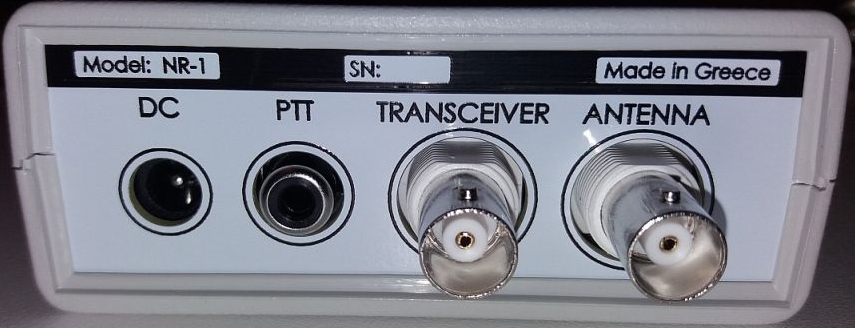
NR-1 can be used by many radios. Because it is an external device, it can be
connected to various radios/receivers without the need to modify them.
NR-1 has a built-in 8-band preselector and helps eliminate intermodulation (birdies)
caused by strong local medium and shortwave stations, on RF direct sampling
radios (eg IC-7300). The preselector is relatively wideband and does not affect
the sensitivity or the waterfall spectrum in the amateur radio bands.
NR-1 has built-in variable gain preamplifier and variable attenuator. Preamplification is
particularly useful in the high frequency bands, where some radios have limited
sensitivity. Variable attenuation helps to reduce band noise for more
comfortable listening to mid/high strength stations.
Comparison of the NR-1 with other noise removal systems (eg. QRM eliminator, X-phase etc):
NR-1 does not require a second (noise) antenna/coaxial-line to operate. Unlike QRM
eliminators, NR-1 does not require an additional “noise” antenna and
therefore no second coaxial cable out of the shack. The main transmit and
receive antenna you are already using is sufficient.
NR-1 is easy to set up. In contrast, QRM eliminators require systematic testing of
various noise antennas in different locations to perform satisfactorily.
NR-1 removes noise from every direction simultaneously. In contrast, QRM
eliminators, depending on the noise antenna setup and their configuration,
remove noise from one direction only each time. If the noise originates or
“travels” through cables and reaches the antenna from different
directions, QRM eliminators do not perform well.
NR-1 removes more than one noise source simultaneously because its principle of
operation is not related to the phase of the noise.
NR-1 does not require constant adjustment. Once set for one band, it usually does not need to be reset. In contrast, QRM eliminators require resetting every few tens of KHz or so.
Kostas has documented all the details of the NR-1 for his own future reference in hispage.
He has also created someYOUTUBE videosas demonstrations of the operation and the effectiveness of this antenna noise blanker.
Many thanks to SWLing Post contributor, Kostas (SV3ORA), for sharing the following guest post which originally appeared on his radio website:
FRG-7 digital display contrast improvement
by Kostas (SV3ORA)
The FRG-7 digital by Marcel Jacobs PA8MA, is a very well thought modification KIT for the Yaesu FRG-7 receiver. It really adds to it one of the things it misses (and it misses a lot) to become a more “serious” receiver in the modern era, the digital frequency readout and S-meter. If you are like me and enjoy classic radio gear, but you do not want to compromise much the every-day usability, I recommend you this KIT. I have to say here that, the first thing you would want to do if you use the receiver for SSB, is to perform my SSB-related mods as well.
When I installed this KIT on my FRG-7 The first thing I did not like about it, was the very bright display which blasts your eyes with light especially at night on a low-lit shack. Not only that, but your eye will condinuously focus on the bright display and you loose the magic of the rest of the radio controls and displays. I wanted the digital display to be one of the parts of the radio and not the major thing that my eyes will look all the time. Marcel was smart enough to include 2 brightness levels in software. The low brightness setting does not actually change the backlight of the display, it just changes the graphics in more dim colors. As a result in either setting, the backlight color is very bright and this decreases contrast a lot. The background of the numbers in the display has a blue-ish color and not true black. Not only that, but the edges of the display, are visible too. I have solved all of these problems with a simple modification to the KIT.
The picture above, shows the display after my modification. The picture is taken on a dim-lit shack using my phone, with no further image processing. What you see in this picture, is exactly what it looks in reality, after my modification. Notice how the background of the display, remains pure black and the numbers and graphics of the display do not blind you anymore and are of the same brightness as the rest of the original backlit graphics of the radio. This allows your eye to wander around to the rest of the nice radio backlit things, without focusing all the time on a bright display. This is very relaxing to the eye and the brain as you scan for stations. You actually only look at the digital display when you want more accuracy. Compare this nice display contrast with the one presented on Marcel’s manual and you will notice the difference.
The modification is really simple and it does not need a schematic. It is just a 22k potentiometer, connected as a variable resistor like shown in the picture. I just cut the second cable (from the left), of the ribbon and then soldered the variable resistor there. That’s it. Depended on the light conditions in which you operate the receiver and on your personal preference, you can set the brighness from full to very dim. In the software setting, set the brightness to maximum. Then use this variable resistor to decrease it to your desired level.
Many thanks to SWLing Post contributor, Kostas (SV3ORA), for sharing the following guest post which originally appeared on his radio website:
TAP: A Morse alternative mode for the HAM, with no need for training
by Kostas (SV3ORA)
Introduction
The thinking of this new mode, came to me when someone posted that he quit the HAM hobby because he did not learn Morse code and he did not want to use computers to do the job for him. Some time I faced a similar situation and I believe many do one day or the other. So I thought that I had to do something about it. It is too bad people quit the hobby or missing the fun of the KEY operation, because of the obstacle of Morse code. No matter what CW operators that already learnt Morse might say, the fact is that Morse requires patience, continuous practice and most importantly time. After all military had dedicated courses on it in the past, so it must be more than true. These are things not all people can, or are willing to do. An alternative that gives the same pleasure like Morse and operates with the same techniques, but requires no training and time must exist. Meet the TAP mode!
Mode description
This mode has its roots to ancient Greece. You may read the article in Wikipedia for more information on the Polybius square. A form of it, was used in the previous century in was times, for in-prison communication. A modified version is presented here by me, that fits perfectly the HAM radio. This modified TAP code scheme, is dedicated to HAM radio and includes the numbers and the letter “k”.
This is all you need to know in order to send and receive TAP. It is easy to follow and easy to generate on paper. This is a 6 by 6 table, with the first six alphabet letters placed in the first line, the next six in the second and so on. After the alphabet ends, the numbers are put in the same manner. Thats it!
Sending TAP
It is better to describe the sending procedure with an example.
To send the letter “i” you send two dots (“i” is on the second row), wait a bit and then send 3 more dots (“i” is on the third column). In other words, you first count the number of rows where the letter exists, then wait a bit and then you count the number of columns where this letter exists. Before sending the next letter, leave a bit of more time, so as to distinguish that this is a separate letter and not the time between rows and columns. Thats it!
Try it now without any transceiver! Write the TAP table on a piece of paper (you do not need to write the row and column numbers), or read it from the website. Tap on your desk with your finger and send some words to the colleague near you. See how easy it is?
There are actually four spacings involved. The spacing between adjacent dots, the spacing between the row and the column, and the spacing between letters and the spacing between words. Follow the PARIS spacing, like Morse code does, if you intent to write a software for it. However, in practice, manual operators would need to consider just two spacings, the spacing between rows and columns and the spacing between letters. These are the most important. Just make the one bigger than the other and communication should be achieved without problems.
Receiving TAP
It is better to describe the receiving procedure with an example.
To receive the letter “i” you listen two dots (“i” is on the second row), then a short scilence time and then listen 3 more dots (“i” is on the third column). In other words, you first listen for a number of dots (this is the row where the letter exists), then sense the scilence and then you listen for the next number of dots (this is the column where the letter exists). The scilence time between two letters is greater than the scilence between rows and columns and this can be distinguished easily. Thats it!
Try it now without any transceiver! Write the TAP table on a piece of paper (you do not need to write the row and column numbers), or read it from the website. Put your coleague to sent you some TAP words and you should be able to decode them by counting the rows and columns in the TAP table.
A programmer that may need to implement the mode in software, should follow the PARIS spacing to distinguish the different parts of the code, as described above.
TAP advantages
Here are some advantages I can think, of TAP in comparison to Morse.
No training is required, start using it imediatelly, even by non-HAM people and kids. This probably is the greatest advantage and this is why most would want to use TAP in HAM radio.
The encoding/decoding square can be drawn easily, it is very easy to remember how to draw it.
Decoding by hardware or software means, becomes very easy, as there are no dashes to account for. Dot lengths can be anything and can be even varying from dot to dot, it does not matter.
All you count, is how many ON-states (taps) there are and the rough timing between them, to decide between a row-column or a letter. Because of this intependency from dashes, the code can be used on any means, radio, light, pipes, walls, desks etc.
If dot lengths are kept very short (up to the point where channel noise allows it), RF amplifiers can be pushed beyond their limits (due to limited duty cycle), or otherwise run cooler within their limits. There are some mediums, like light communication, where bright pulses of light can be produced easily (eg. xenon tubes), but not kept for duration and TAP is ideal on them.
TAP disadvantages
Here are some disadvantages I can think, of TAP in comparison to Morse.
Speed limit issues probably. TAP beginners achieve for sure faster speeds than Morse beginners. However, a trained Morse HAM, can achieve greater speeds with Morse.
Learning the table by heart, can be tricky in comparison to Morse. However war prisoners had tricks to learn by heart the 5×5 TAP square.
Not known (yet) among the HAM community, like any new mode. Why not change that by let HAMs know about it?
TAP common points to Morse
There are some common points shared between TAP and Morse code.
Both are relatively slow modes.
Both are ON/OFF keying modes, efficient class-E amplifiers can be used.
Both share the same channel bandwidth and noise-related characteristics.
Both are human-oriented, although TAP does not require training. Both share the PARIS timing when implemented in software.
Both allow for the “joy of the KEY”. You send TAP with the same equipment as Morse.
Both are ideal for homebrew QRP, due to efficiency and transceivers simplicity.
Many thanks to SWLing Post contributor, Kostas (SV3ORA), for sharing the following guest post which originally appeared on his radio website:
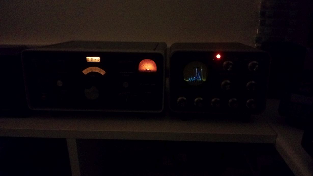
Collins 51S-1 band scope using a Heathkit SB-620
by Kostas (SV3ORA)
The purpose of this project, is to connect a Collins 51S-1 receiver with a Heathkit SB-620 “scanalyzer”, so as to give the 51S-1 band scope capability. Right into the schematic presented below, a slight modification is needed to the 51S-1. I usually do not do modifications to old equipment unless absolutely needed and even when I do so, I take care for them to be easily undone and to modify them as little as possible.
The modification to the 51S-1 is simply a small coupling capacitor connected to the plate of the mixer tube V4A and a short run of thin coaxial cable, connected as shown, to one of the several SPARE RCA connectors at the back of the 51S-1. Collins engineers were smart enough to include SPARE RCA connectors at the back of the radio, which are not connected to anything inside the radio circuit, to be used for different future purposes. So we do not have to drill any holes to the chassis of the precious receiver, which would be catastrophic.
Click to enlarge.
The coupling capacitor is just 5pF, so compared to C125, this presents only a tiny fraction of the loading to V4A plate, i.e. not affecting the normal operation of the receiver. Note, you cannot take directly the 500KHz IF output that is originally provided by the 51S-1 RCA in the back of the radio. This is because this IF is AFTER the filters, so it is a narrow IF. We need WIDE IF for the scanalizer to work properly, so you have to perform this tiny modification to the 51S-1.
No need to say that the SB-620 needs to be re-tuned for 500KHz instead of 455KHz. I was unlucky and my SB-620 did not have the appropriate L3 to be tuned to the IF of 455/500KHz. Mine had the L3 used for an IF of 5.2-6MHz. I converted the SB-620 to work down to 500KHz by using this original higher-frequency L3 and adding two additional inductors to it, one at its bottom and one at its top, so as to make L3 larger. The additional bottom inductor I added (connected from the bottom of L3 to the ground) was a 15uH choke. The additional top inductor I added (connected from the top of L3 to C3 and C5), was a 455KHz IF CAN transformer (the one with the adjustable yellow-painted cap) taken out of a transistor radio. Of course I have removed the internal capacitor of the transformer before using it. My transformer had something like 200-300uH in the mid-set point. It is not too critical as this is a tunable transformer.
By making this modification to the SB-620 you can bring the 5.2-6MHz L3, down to 500KHz. Of course the slug of L3 now has limited tuning range. But we can coarse tune the hybrid L3 now, by tuning the IF transformer that has been added. This solution worked like a charm and the original L3 is still fit in place, looking original and helps in fine tuning if needed. For the optional mixer input (points A, B, C on the SB-620), I used circuit #1, but I did not notice any real difference from circuit #3. RFC1 is 304uH and I connected three 100uH chokes in series to make this RFC.
The solution described in this page, will add a huge value to your vintage receiving station. SWLing feels just different by having an all-tubes computer-free band scope. Here is a picture of the setup, nicely glowing in the night. That P7 CRT blue phosphor with its green afterglow “memory” effect looks amazing! Narrow resolution is actually only achievable, because of this afterglow of the CRT, which allows for much slower sweep rates.
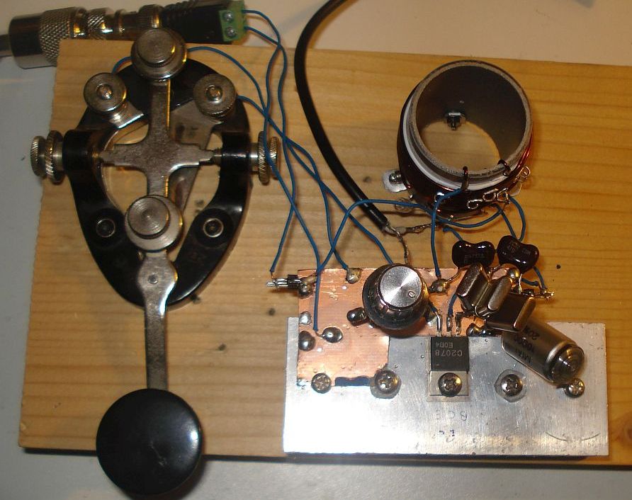
PC keyer and AM modulator: A 15-components versatile keyer and powerful PSU modulator for the EMTX (Emergency Transmitter)
by Kostas (SV3ORA)
Schematic of the keyer and modulator (on the left) for the EMTX. The EMTX schematic is shown as well on the right, to determine the connections to the keyer/modulator.
Introduction
My very successful emergency transmitter (EMTX) was only capable of CW or other slow speed ON/OFF keying modes. Then I thought, why not “give voice” to the design? CW is good, but it is half of the fun. If you could use your simple CW transmitter to send out your voice as well, this would be great. You could now chat comfortably on the nets or use any digital radio amateur mode and have much more fun. The simplest modulation you can apply to an existing CW transmitter, is the AM modulation. And whereas this is an old modulation, mostly abandoned by HAMs due to beeing inefficient, there are still AM nets on HF. But do not forget, AM can also be heard by SSB receivers by zero-beating the receiver to the AM carrier. So you could still use your simple AM transmitter to QSO with the SSB guys!
Along with the modulator, there is also a versatile keyer embedded to the circuit, so that the EMTX can be manually keyed with different ways or automatically keyed by audio tones from the PC. For more information on the keyer, keep reading.
The AM modulator
In the old days, the most common way to apply AM modulation was to modulate the high voltage to the plate of the tubes, using a transformer and a powerful audio amplifier. In low voltage solid state circuits, you can still do it using transformers, but you can also use series transistors instead of the transformer. All these things require many components and/or powerful AF amplifiers if one is to modulate higher power transmitters. This does not match the keep-it-simple design I am trying to achieve here.
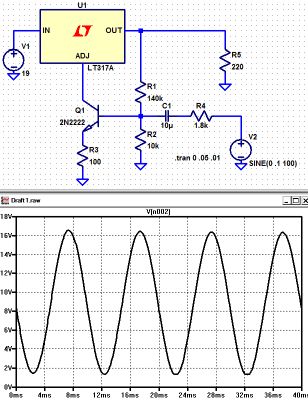
So I thought of a simple trick with the use of the extremely common LM317 regulator, used as a modulated power supply. This modulator uses just a few common cheap components and it is able to achieve remarkably good modulation levels for it’s parts-count, just from line audio input. It juices every bit of the internal circuicity of the LM317, just look at where the base current of the 2N2222 comes from.
The AM modulator is a kind of novelty. Whereas there is nothing special in a modulated power supply, this circuit has some interesting properties. It is amazingly sensitive and it is able to provide lots of modulated current to any low power transmitter that it can feed. It can be easily driven by the line output of any laptop (around 20% volume) and provide a very good depth modulation to the transmitter. Charles Wenzel was kind enough to do a simulation on the circuit I developed, which is shown below.
His simulated circuit is a slight variation (for measurement purposes). The resistor to ground on the base stabilizes the bias and the ratio of R1 and R2 set the output voltage (0.6 volts across R2 gives about 8 volts across R1). He put in an emitter resistor just for good measure. Same for the series resistor from the source. Charles words, “I don’t know how believable these results are but it looks pretty darned good!”.
The circuit is being used as a current booster, the current being the supply to the transmitter and dependent on the voltage it produces. The LM317 always tries to keep 1.25V between it’s output pin and “adj” pin but where we benefit here is the current at the “adj” pin is very low, so it is easier to apply audio to it. Effectively, the error amplifier inside the voltage regulator is used as an additional amplifier stage. The output pin voltage varies according to the voltage on the “adj” pin so if we use it to bias the transistor we get negative feedback which improves the quality of the modulation. More output voltage = more bias current = lower output voltage. The result, is a very cheap, low components-count, very sensitive AM modulator that can supply lots of power to easily drive the transmitter and produce a clean and deep AM modulation!
The AM modulator bias is set with the 1M potentiometer. Depended on the bias level, the idle carrier on the EMTX can be set from about 0.5W all the way up to 8W. Needless to say that this modulator can modulate any similar power transmitter, not just the EMTX.
The keyer
If it is to modulate the EMTX from the PC, so as to use the different digital modes, there must be a way to key it also from the PC. This is why I decided to embed into the same circuit, a PC keyer which is triggered by the line audio of the PC, but also triggered manually (internal or external key). Keying by audio tones was decided, because modern PCs do not have LPT ports to trigger directly by DC. This keyer uses a reed relay to reliably, fastly and scilently key the EMTX, which is activated by a transistor. The base current for the transistor is derived from the audio signal after rectification. The incoming audio from the PC line passes through the mini audio transformer to increase its voltage, it is rectified and then charges the shunt capacitor to drive the base of the transistor. The keyer “speed” (decay) is determined by the shunt capacitor size. The circuit starts to trigger from about 50-60% of my sound card output signal level.
The relay used to key the EMTX, must be able to tolerate at least 1A of switching and carrying current. Note that the relay contacts switching current is not the same as the contacts carrying current. Reed relays are the best especially if you want long relay life, noiseless operation and very fast switching speeds, like the ones used in Hellshreiber. If you can’t find such a relay, you can use a reed switch capable of 1A of switching and carrying current and then place a suitable electromagnet close to it, so you can build the relay yourself. If you do so, find the best point where the reed switch responds to the electromagnet.
The keyer relay must be as close as possible to the emitter of the transistor used in the EMTX. The connectors at the back of the EMTX and the keyer/modulator have been physically placed so that when the two units are side by side, a very short link cable is required for this purpose. With the two devices placed close together, you can now use any length of cable for your manual external key, which is now connected to the “EXT” connector of the keyer/modulator.
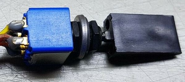
The keyer does also have an internal mini straight key. I find this idea very nice, to avoid extra cables. It is not the most convenient key in the world, but it is there along with the transmitter every time you need it. By using a special panel switch from apem, I was able to triple this switch usage for the different modes of the keyer. The vinyl lever cap you see in the next picture, is the original part of the switch, to make it easier to key with your finger. But you may build such a part on your own, to fit on other switches types.
The switch is an ON-OFF-(ON momentary) switch type. In the default (middle) position, only the PC keying action is activated. In the top position (ON), the keyer is always active, which is useful for broadcasting audio (into a dummy load). The bottom (ON momentary) position, is the manual PTT action. This is used as a straight key on OOK operation, or as a PTT on AM voice operation. Simple and effective!
Initially, I used one channel of the PC sound card for triggering the keyer and also as an AF signal for the AM modulator, but this caused several problems of unreliable keying or distortion. So I decided to use a second separate AF input (KAF) to key the keyer. This second input, uses the other channel of the stereo sound card. With the addition of this input, there is no interaction between the keyer and the modulator. The AF levels that the keyer and the modulator require, can be set independently. Instead of adding more hardware for the purpose, I have chosen to set these levels by adjusting the volume and the balance of the sound card, which works great. Also, programs like Fldigi, have options for using one of the two channels of the stereo sound card as a keying interface (PTT channel), which makes the keying efen more reliable. When the program is in transmit mode, a continuous tone is heard on the PTT channel. This steady tone, is used by the keyer as a reliable keying signal, independent of the audio signal of the digital mode that modulates the modulator. This solution works very reliably for any mode. But if the program you are using does not have an option for a PTT channel, that is ok, as the keyer works reliably even without this feature. For voice communication or broadcasting music (into a dummy load) you just use the internal key switch as a PTT to handle these modes.
Results
Prior to building the keyer and the modulator in the same device, I had tested the circuits independently quite a few times, to ensure the results can be reproduced. The modulation quality and depth out of the AM modulator have to be listenned to be believed. I have not made any linearity measurements, I just trust my ears on this one. It works great on music as well as on voice. Apart from that, this is the most sensitive AM modulator I have ever built, requiring only a small fraction of the line level output of the PC sound card.
When modulated by this modulator, the EMTX shows no audible signs of FM modulation. I switched my receiver to SSB and I could perfectly zero beat the AM modulated music signal which stayed on frequency and it’s tone did not change during loud audio signal music. Switching back and forth from SSB to AM modulation on the receiver, I did not notice any difference in the audio quality, apart of course from the narrower bandwidth on SSB modulation, due to the narrower IF filter inside the receiver on SSB.
The AM/OOK switch is used to select the modulation applied to the EMTX. When the keyer is set to be triggered by audio from the PC, at the OOK position, the EMTX is just switched on and off by the audio tones applied to the keyer, or by the manual key, internal or external (connected to the “EXT” connector). At AM position, the EMTX is switched on by the audio signal applied to the KAF connector and at the same time AM modulated by whatever audio signal is applied to the AF connector. On voice communications, the momentary position of the internal key is used as a PTT. On music broadcasting (into a dummy load) the non-momentary position of the internal key is used to keep the keyer always active.
Photos
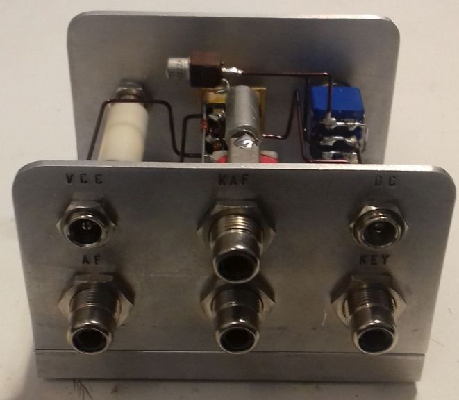
Back connections to the EMTX.
Pictures of the finished keyer/modulator. You don’t have to build it that nice-looking if you don’t care.
Modulator prototype and EMTX built on a breadboard. Yes it worked just fine onto a piece of wood.
Thank you so much for sharing this brilliant and simple project with us, Kostas. Your handiwork is absolutely brilliant too!
Many thanks to SWLing Post contributor, Kostas (SV3ORA), for sharing the following guest post which originally appeared on his radio website:
Emergency transmitter: An 8-component, high-power 40m/30m transmitter to get you quickly on the air
by Kostas (SV3ORA)
Introduction
QRP is all about doing more with less. This is more than true, with the construction of this cheap, simplistic transmitter presented here. It is designed primarily as an emergency transmitter (EMTX) that can be built or serviced in the field or at any home. However, it can be used as a HAM radio transmitter as well. Do not judge by its low components count though. This transmitter is powerful, more powerful than anything the QRPers would dream of. It is just remarkable how 8 components can lead in so much output power, that lets you communicate with a big part of the world, when propagation conditions are right. It is very difficult for a circuit to match that kind of simplicity in balance with such performance.
Following my detailed instructions, the EMTX can be reproduced easily, within hours. The result is always success, this is one of the circuits that are not critical at all and a successfully working transmitter can be reproduced every time. I have built this transmitter several times, using similar components (even toroids) and it always worked. The transmitter meets the next expectations:
1. Output power (including harmonics): A few mW up to 15W (depended on transistor, crystals and voltage/current used) at 50 ohm.
2. It can drive any antenna directly, 50 ohm or higher impedance, without external tuners.
3. Bands of operation: Currently 40m, 30m
4. Mode: CW, Feld-Hell (with external switching circuit), TAP code and any other ON/OFF keying mode. AM modulation has been easily applied too.
5. Options like reverse polarity protection diode (useful in the field when testing different unknown polarities PSUs) and current meter (for easier tuning) are available.
The challenge
The purpose of this transmitter is to be used primarily as an emergency transmitter. This poses several challenges that influence the design of the transmitter:
1. It must be able to be built or serviced easily in the field or at any home, with components that could be salvaged from near by electronics sources or a small electronics junk box. This means that components count should be kept very low and they must not be rare to find but commonly available parts. As a side effect cost would also be kept small, if one is to buy any component. Also, the active components must be interchangable with many other devices without the need for the design or the rest of the circuit components to be changed.
2. It must be able to operate from a very wide range of DC voltage sources and at relatively low current, so that common house power supplies could be used to supply power to it. Such devices include linear or switched mode power supplies from laptop computers, routers, printers, cell phone chargers, Christmas lights or any other device one might have available.
3. It must be capable of transmitting a powerful signal, so that communication is ensured. An emergency transmitter that is capable of a few mW of output power, might be heard locally (still useful, but there are handheld devices for that already) but isn’t going to be of much usage if it can’t be heard really far away.
4. It must be capable of loading any antenna without external equipment required. In an emergency situation, you just don’t have the luxury of building nice antennas or carrying coaxial cables and tuners. There may be even extreme cases where you can’t even carry a wire antenna and you depend on salvaging wire from sources in the field to put out a quick and dirty random wire antenna.
5. Adjustments of the transmitter should be kept minimum without the help of any external equipment and there must be indication of the correct operation of the transmitter or the antenna in the field.
Components selection
The transistor:
This transmitter has been designed so that it can operate with any NPN BJT in place. This includes small signal RF and audio transistors and high power RF transistors like the ones used on HF amplifiers and CB radios. Despite 2sc2078 is shown in the schematic, just try any NPN BJT in place and adjust the variable capacitor accordingly. When you are in the field, you do not have the luxury of finding special types of transistors. The transmitter must operate with any transistor in hand, or salvaged from near-by equipment. Of course the power capability of the transistor (as well as the crystal current handling) will determine the maximum VCC and current that can be applied to it and hence the maximum output power of the transmitter. Some of the most powerful transistors I have used, come out of old CB radios, such as the 2sc2078, 2sc2166, 2sc1971, 2sc3133, 2sc1969 and 2sc2312. There are many others. As an example, the 2sc2078 with a 20v laptop PSU, gave 10-12W of maximum output power into a 50 ohms load.
Schematic of the 8 components EMTX for the 40m/30m bands. Components with gray color are optional.
The crystal:
This is the most uncommon part of the transmitter. You have to find the crystal for the frequency that you want to operate on. Crystals within the 40m or 30m CW segments are not that common. Further more if you operate the transmitter at high powers and currents, you will notice crystal heating and chirp on the frequency of the transmitter. The current handling capability of your crystal die inside the crystal case, will determine the chirp and the amount of crystal heating. You can still work stations with a chirpy transmitter provided that the chirp is not that high, so that it can pass through the CW filters of the receivers. However, if a small chirp annoys you or if this chirp is too much, then you have to use these vintage bigger size crystals (e.g. FT-243), that can handle more current through them. But these are even more uncommon today.
The approach I have used in my prototype, was to connect more than one HC-49U crystals of the same frequency in parallel, so that the current is shared among them. This reduced the chirp at almost unnoticeable levels, even at high output power, just if I was using a single FT-243 crystal, or even better in some cases. Again, this is optional, but if you want to minimize chirp (and crystal heating) without searching for rare vintage crystals, this is the way to go.
A bit of warning. If you notice a very high chirp when plugging in a crystal to the EMTX, you should consider this crystal as inappropriate for this transmitter, as it cannot handle the current required. If you continue to use this inappropriate crystal, you could easily crack it inside and set it useless. Don’t use these tiny HC-49S crystals, they won’t work.
The current meter:
A 1Amp (or even larger) current meter can be used to monitor the current drawn by the transmitter during key down. The recommended current operating point is anywhere between 450mA to 1A, depended on the output power (and harmonics) level you want to achieve. The current point is set by the variable capacitor. I would avoid setting the current to more than 1Amp, although it can be done. The use of the current meter is optional, but along with the incandescent bulb, will give you a nice indication of the correct tuning of the transmitter, so that you do not need to have an external RF power meter connected to the transmitter output. If you do have, then you can remove the current meter. If you don’t have a 1Amp analogue meter available, but a smaller one, you can parallel a low value power resistor across the meter. In my case, I only had a 100uA meter and I paralleled a 0.15 ohms 5W resistor across it to scale down 1Amp to 100uA, The resistor value depends on the internal meter resistance so you have to calculate this for your specific meter. When the 2sc2078 is used at 20V, 500mA in the current meter indicates around 5W of output power, 600mA indicates around 6W, 700mA 7W, 800mA 8W, 900mA 9W and 1A around 10W. So the current meter can be used as sort of power meter without the need to do any scaling on it.
The incandescent bulb:
A current meter alone, without the use of the incandescent bulb, will not give you the right indication of the operation of the transmitter. In some cases, the transmitter might be drawing current without actually generating much, or even any RF. When you are in the field you do not want to carry extra monitoring equipment with you. The incandescent bulb will light on when the transmitter oscillates. It monitors the actual RF signal, so it’s brightness changes according to the amount of RF power the transmitter produces. Along with the current meter reading, this is just what you need to know in order to set the variable capacitor properly. Note that the bulb will not lit at very low signal levels. The one used in the prototype starts to glow up from a bit less than 1W. Miniature incandescent bulbs may not be that easy to find nowadays. However, there is a good source of these, that almost anyone has in their houses. This source is the old Christmas lights. You do save old Christmas lights, don’t you? The incandescent bulb indicator as well as it’s single turn winding on the transformer, are optional components. If you have an RF power meter connected to the transmitter, you can remove these.
The diode:
The protection diode is an optional component to the circuit. If you are in the field, correct polarity of a power supply may not be obvious. Without a multimeter it might me difficult to determine the correct polarity of the PSU. A power diode (I used a 6A one) will protect the transistor from blowing up in the event that reverse polarity is connected to the circuit.
The Cx and Cy:
The Cx and especially the Cy capacitors need to be of good quality. The Cy will get hot on high output power if it isn’t. In the tests, I have used homemade gimmick capacitor and even double-sided PCB as a capacitor for Cy and they all got hot at high power. Silver mica capacitors run much cooler and they do make a small difference in the output power, so I suggest to this type. Cy must be able to handle quite a lot of voltage, so silver mica type is ideal.
The variable capacitor:
The variable capacitor can be air variable or ceramic, although I prefer air variables in tis application. In any case it must be able to handle a high voltage just as the Cy.
The key:
The key directly shorts the transistor emitter to the ground, therefore it is a part of the active circuit. For this reason, I suggest the key leads to be kept as short as possible. The key must be able to handle the voltage (20v) and current (up to 1A) on its contacts, which is usually not a big deal.
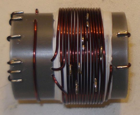
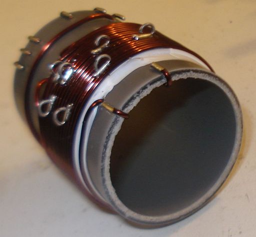
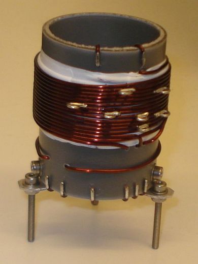
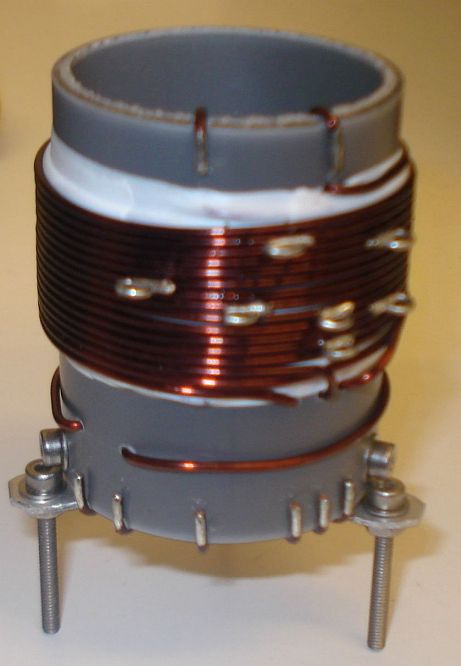
Transformer construction
The construction of the transformer is shown below step by step. Note that if you decide that you don’t need to drive higher impedance loads but just 50 ohm ones (eg. antenna tuners or 50 ohm matched antennas), you just need to wind 2t in the secondary and not 14t. You also don’t need any taps of course.
Step 1:
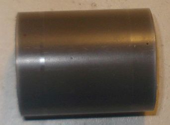
Take a piece of 32mm external diameter PVC pipe from a plumber’s shop. Alternatively, a suitable diameter pills box can be used, or any other suitable diameter plastic tube.
Step 2:
Cut a 4cm piece out of this tube. 4cm is the minimum length required.
Below a 4cm PVC tube has been cut in size.
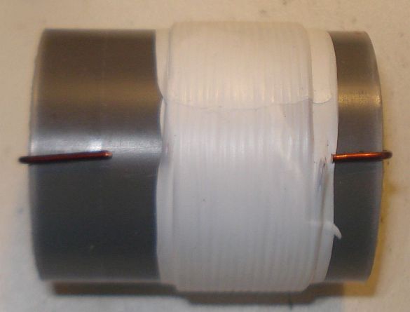
Step 3:
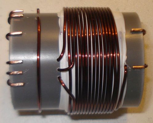
Wind 16 turns of 1mm diameter enameled wire onto the PVC pipe and secure the winding in place as shown in the picture below. Notice the winding direction of the wire. This is the primary of the transformer, the one that is connected to the two capacitors. Notice that this winding is wound a bit offset to the right of the pipe.
Step 4:
Wrap the winding with 3 turns of PTFE tape. It can be bought at any plumber’s shop, just like the PVC pipe. The PTFE tape will help in keeping the second layer turns in place and it will provide extra insulation.
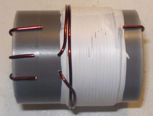
Step 5:
Wind 2 turns of 1mm diameter enameled wire on top of the primary winding and secure the winding in place as shown in the picture below. Notice the winding direction of the wire, as well as it’s position relative to the primary winding. This is the feedback of the transformer, the one that is connected to the collector of the transistor.
Step 6:
Wind 14 turns of 1mm diameter enameled wire on top of the primary winding, starting from just next to the 2 turns one and secure this winding in place as shown in the picture below. Notice the winding direction of the wire, as well as its position relative to the primary and the 2 turns windings. This is the secondary (output) of the transformer, the one that is connected to the antenna. At this point do not worry about the taps yet.
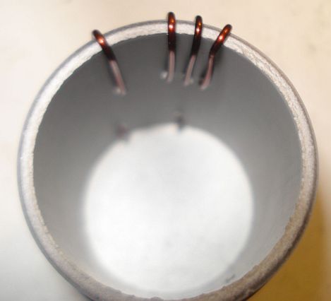
Notice in the picture below, the way the windings are secured in place onto the pipe. The wire ends are passed through the pipe using small holes and then bent towards the ends of the pipe and once more to the surface of the pipe, where the connections will be made.
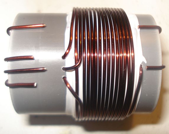
Step 7:
Wind 1 turn of 1mm diameter enameled wire onto the pipe and secure the winding in place as shown in the picture below. Notice the winding position relative to the other windings. This 1 turn winding is placed about 1cm away from the other windings. This is the RF pick up winding, the one that is connected to the incandescent bulb.
Step 8:
Use a sharp cutter (knife) and carefully scrap the enamel of all the windings ends. Do not worry if you cannot scrap the enamel at the bottom side of the wire ends (that touches to the pipe). We just want enough copper exposed to make the connection.
Step 9:
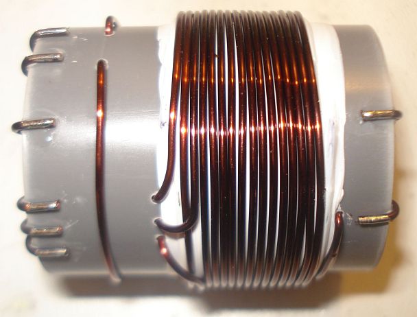
Tin the scrapped wire ends, taking care not to overheat them much.
Step 10:
Now it’s time to make the taps on the secondary winding. Use a sharp cutter (knife) and very carefully scrap the enamel of the wire at the tap points (number of turns). Take much care not to scrap the enamel of the previous and the next turn from each tap point. Do not worry if you just scrap the enamel at the top of the wire (external area). We just want enough copper exposed to make the connection.
Make each tap, a bit offset from the near by taps, like shown in the pictures. This will avoid any short circuits (especially at the 4, 5 and 6 taps) and it will allow for easier connections, especially if alligator clips are used to connect to the taps.
Step 11:
Tin all the tap points, taking care not to overheat them.
Step 12:
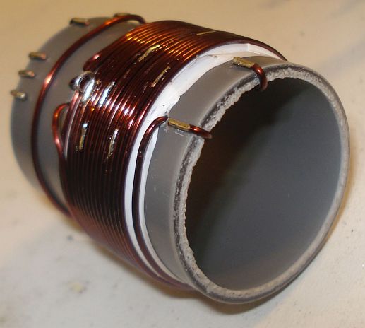
This step is optional and it depends on how you decide to do the connections to the taps. You may solder wires directly to the tap points, but in my case I wanted to use alligator clips, so I did the next: I took a piece of a component lead and soldered it’s one end to each tap point. Then I bent the component lead to U-shape and cut it accordingly. This created nice and rigid tap points for the alligator clip.
Step 13:
This step is optional and it depends on how you decide to mount the transformer to your enclosure. In my case, I wanted to create three small legs for the mounting. I cut three pieces of aluminum straps and made holes at both their ends. I made three small holes onto the transformer pipe end and mounted the aluminum straps using screws. After mounting them, I shaped the straps to L-shape. Then I used three more screws to mount the transformer to the enclosure.
The completed transformer is shown in the pictures above and below. The 6 connection points at the bottom of the pipe, are the low voltage points, whereas the 2 points at the top of the pipe, are the high voltage points.
If you have built the transformer as described, the bottom connections are as follows (from left to right):
Wire end 1, connected to the incandescent bulb
Wire end 2, connected to the incandescent bulb
Wire end 3, connected to the current meter
Wire end 4, connected to the current meter
Wire end 5, connected to the GND (ground)
Wire end 6, connected to the transistor collector
The top connections are as follows (from left to right):
Wire end 1, connected to the 25pF variable capacitor and the Cy fixed.
Wire end 2, is the 14th secondary tap and it is left unconnected, or tapped to the appropriate impedance antenna.
Videos of the EMTX in operation
I have made two small videos of the EMTX in operation.
The first 13.5MB video (right click to download), shows the operation when the transmitter is set for a bit less than 10W of output power.
The second 3.5MB video (right click to download), shows the operation when the transmitter is set for about 5W of output power.
EMTX chirp analysis
Every self-exited power oscillator (and even many multi-stage designs) exhibits some amount of chirp. Chirp is mainly considered as the sudden change in frequency when the power oscillator is keyed down. Apart from chirp, there is also the longer term frequency stability that may be considered. The chirp in the EMTX is surprisingly low, if it is built properly. Hans Summers, G0UPL has performed a chirp analysis on my EMTX (PDF) and the EMTX built by VK3YE and presented on YouTube. Hans, performed the analysis from the video/audio recordings of both transmitters. I sent him two videos, one with the EMTX set for an output power of 10W and one where it is set for 5W. The chirp at worst case (10W) was about 30Hz and at 5W in the order of 10Hz or so. Being so small, the chirp is almost undetectable by the ear and it surely poses no problems when passing the tone through narrow CW filters. This is an amazing accomplishment from a transmitter so simple and so powerful.
EMTX harmonics measurement
Every unfiltered transmitter will excibit harmonics at it’s output. This means that the output waveform has some distortion in comparison to a pure sinewave. Many of the transmitters I have seen, present a very distorted output waveform and absolutely need a LPF if they are to be connected to an antenna. I can’t say that this is true for the EMTX, because surprizingly, it has low distordion, despite the high output power it can achieve. Although a LPF is always a good idea, it is not that much needed on the EMTX. However you have to use one to comply with the regulations.
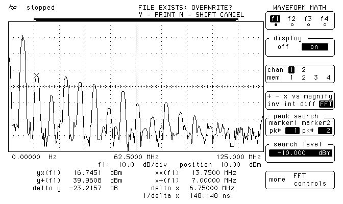
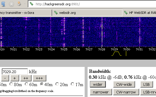
The image above, shows the measurements on the output of the EMTX, when it is set closely to 10W at 50 ohms. The main carrier is exactly at 9.9W and all the harmonics are less than 50mW! Also, the harmonics, do not extend into the VHF region.
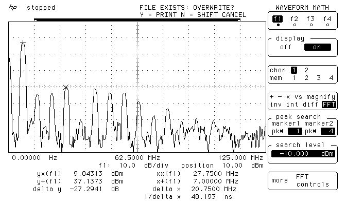
The image below, shows the measurements on the output of the EMTX, when it is set closely to 5W at 50 ohms. The main carrier is exactly at 5.17W and all the harmonics are less than 9.6mW! Again, the harmonics, do not extend into the VHF region.
These small harmonics levels aren’t going to be heard very far at all, compared to the powerful carrier. This means only one thing. A LPF, although a good practice, is not mandatory in this transmitter. But you should better use one so that you comply with the regulations.
Many HAMs use just a watt meter to measure the output of their homebrew transmitters. This is not the proper way of doing it, because the watt meter is a non-selective meter. It will measure both the fundamental carrier and the harmonics, without being able to distinguish them. So in an unfiltered transmitter, or in a transmitter with a simple (often non measured) LPF, this way will give a totally false reading of the output power of the transmitter at the set frequency.
The proper way of accurately measuring the output power of a transmitter and the harmonics levels, is a spectrum analyzer. The FFT available in many modern oscilloscopes, having a dynamic range of approximately 50-55dB, is adequate for this purpose as well. A 50 ohms dummy load must be connected at the transmitter output and then the high impedance probe of the scope, is connected to the output of the transmitter as well. This was the way that the above measurements have been performed.
WebSDR tests
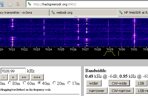
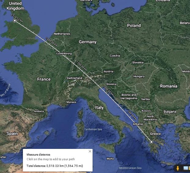
Here are some test transmissions, to determine how far one can get with such a transmitter. I have to say that there is an antenna tuner between the EMTX and my inefficient short dipole (not cut for 40m and not even matched to the coaxial). However I could still cover a distance of more than 2500Km even on the 5W setting.
A screenshot of the transmitter signal, as received on a WebSDR 2500Km away and when the EMTX is set for an output power of 10W.
Below, is a picture and an audio recording of the transmitter signal, as received on the same WebSDR and when the EMTX is set for an output power of 5W.
Photos
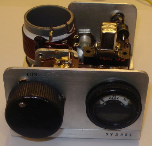
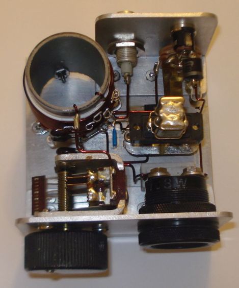
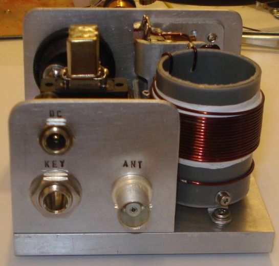
Pictures of the finished transmitter. You don’t have to build it that nice-looking if you don’t care.
EMTX prototype built on a breadboard. Yes it worked just fine onto a piece of wood.
This is a phenomenal project, Kostas. Thank you so much for sharing it with us. I love the simplicity of this design–truly form following function. With a little patience, anyone could build this transmitter.
Many thanks to SWLing Post contributor, Kostas (SV3ORA), for sharing the following guest post which originally appeared on his radio website:
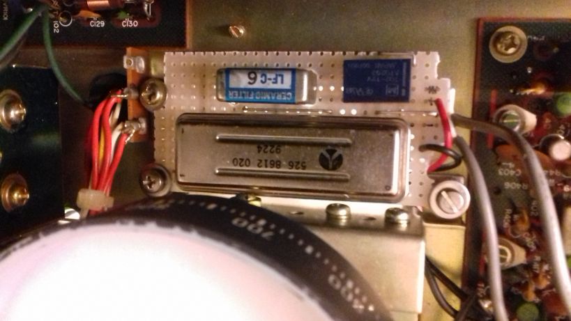
How to install a mechanical SSB filter on the Yaesu FRG-7
by Kostas (SV3ORA)
The Yaesu FRG-7 is a general coverage MW/SW receiver that uses the Wadley Loop system for stabilizing the frequency tuning. The receiver has a good sound on AM mode, that reminds me the tube receivers sound. However, on sideband mode, it is pretty much useless. The IF ceramic filter that is used, does not have enough selectivity to reject the opposite sideband. No matter if the front panel mode selector switch states USB/CW and LSB, these just shift the BFO, nothing more. The receiver is a DSB set not SSB. A cheap way you can accomplish single signal sideband reception with the FRG-7 is described in this link. Whereas it works, it increases the audio bandwidth of the signals to the high pitch.
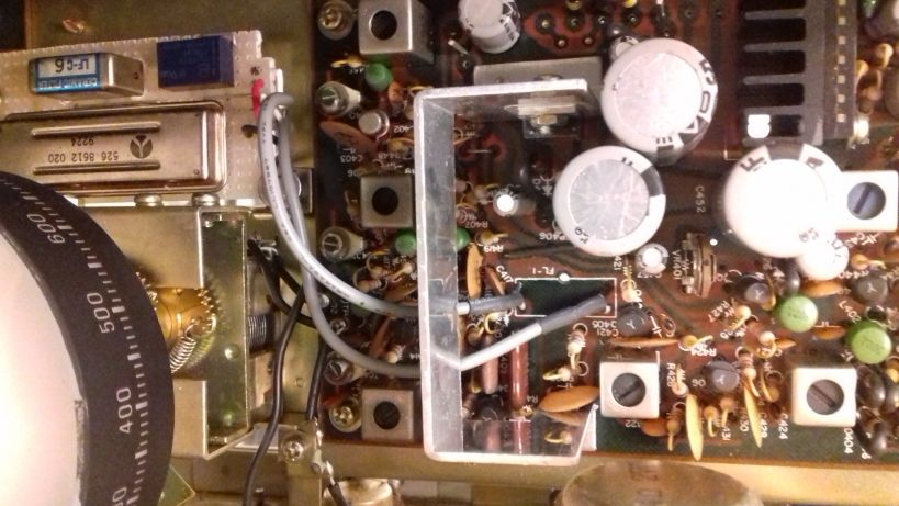
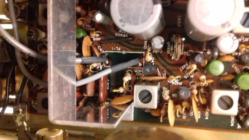
A better approach is to install an additional mechanical filter to the receiver. This of course requires expensive 455KHz mechanical filters, but if you have one in hand or if you are willing to pay for the improvement in performance, then this is the recommended option. But you can’t just desolder the ceramic filter of the receiver and solder a mechanical filter in place. On AM mode, you need wider bandwidth, but on SSB mode you need narrower. So both filters must be in place and a selection must be done in each mode. Thankfully, this modification is pretty easy on the FRG-7 and it does not require any modification of the external appearance of the radio.
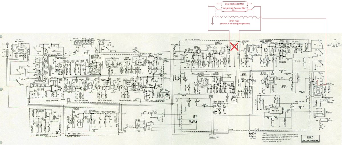
The schematic of the FRG-7 is shown above. Everything with red color, are part of the modification. The modification is pretty straight forward. You have to desolder the original ceramic filter from the FRG-7 PCB and install it on a separate PCB along with the new 455KHz mechanical filter. To select between the two filters, a 9-12v DPDT relay can be used and it must be connected as shown in the schematic. The power for the relay coil is derived from one section of the mode switch (S3d). On USB or LSB modes, the BFO is energized and this power is also used to energize the relay, which in turn switches to the narrow mechanical filter on these modes.
A good place for the new PCB that accommodates the filters, is just below the main tuning dial of the receiver. There is a hole there and three screws, which can be used to also hold this PCB in place. I needed to replace these screws in mine with longer ones, because I used spacers to prevent the PCB from touching the chassis. But this is optional.
Two small pieces of coaxial cables are used to connect the new PCB to the pads of the ceramic filter, that has been now removed from the original PCB of the receiver. Ground these cables on both ends.
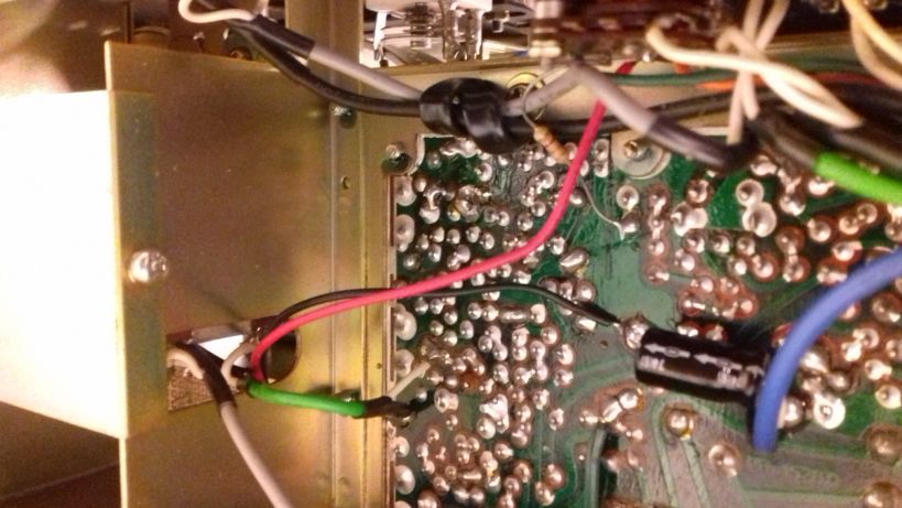
The power cables for the relay coil (shown with red and black in the picture above), are passed below the PCB to the chassis opening and through a hole to the bottom of the original PCB of the receiver. The ground wire is soldered to the filter ground point and the red wire is soldered to the mode selector switch S3d. S3d is the outer wafer onto the switch. Use a multimeter to find the contact of the switch that has VCC when the mode is switched to USB or LSB. This is the point where you want to connect the red wire.
After installing everything, you should perform an alignment of the TC404 and the T406 in the BFO section as described in the manual. This requires a frequency counter, but I did my alignment by simply adjusting the two controls by ear, until I got roughly the same pitch on LSB and SSB audio bandpass. These controls interact, so you have to do a bit of back and forth in both of them. It is very easy.
After installing the modification and aligning the receiver, the result is pretty obvious. No more DSB reception, SSB signals are received just once in the dial and their bandwidth is limited as it should on SSB. The mechanical filter I had, was a bit narrow (2.1KHz) so I can also hear a bit os “seashell” sound on SSB, but SSB voice signals are perfectly understood. It is interesting that the audio volume between the ceramic filter and the mechanical filter was just about the same, which indicates that there is no additional loss in the newly installed filter. Another interesting thing is that there was no need for any impedance matching using active devices or transformers on the mechanical filter. It worked just by directly connecting it. Neither it’s loss, not it’s response seems to be affected by any possible impedance mismatches.
Note that Collins produced both symmetrical and asymmetrical mechanical filters (yes they used two filters, one for USB and one for SSB in some of their gear). My filter is a symmetrical one (same roll-off response curve on both sides of the filter passband). If you use an asymmetrical filter, expect a bit different pitch when switching from LSB to USB and vice versa. Not a huge problem, but just a note.
By performing this simple modification, you will end up with an FRG-7 receiver that is trully selective, allowing for real SSB reception. Most importantly you do not ruin the appearance of your precious FRG-7, but just improving it’s performance. This modification would probably be appreciated much when deciding to sell your FRG-7 to someone else.
Thank you for sharing this practical and affordable project with us, Kostas!