 Many thanks to SWLing Post contributor, Paul Evans, who first tipped me that Environment Canada is ending Weatheradio and the Hello Weather service effective March 16, 2026.
Environment and Climate Change Canada (ECCC) has posted the following notice:
Change to services:
Starting March 16, 2026, Weatheradio and Hello Weather services will be permanently disconnected.
You can get radio marine forecasts via the Canadian Coast Guard. For your local weather forecasts and alerts, visit the interactive weather map or download the WeatherCAN app.
If you use Weatheradio in Canada (especially for “always-on” alerting via a dedicated receiver), you’ll want to take note of what’s changing, what isn’t, and what alternatives ECCC is directing users to.
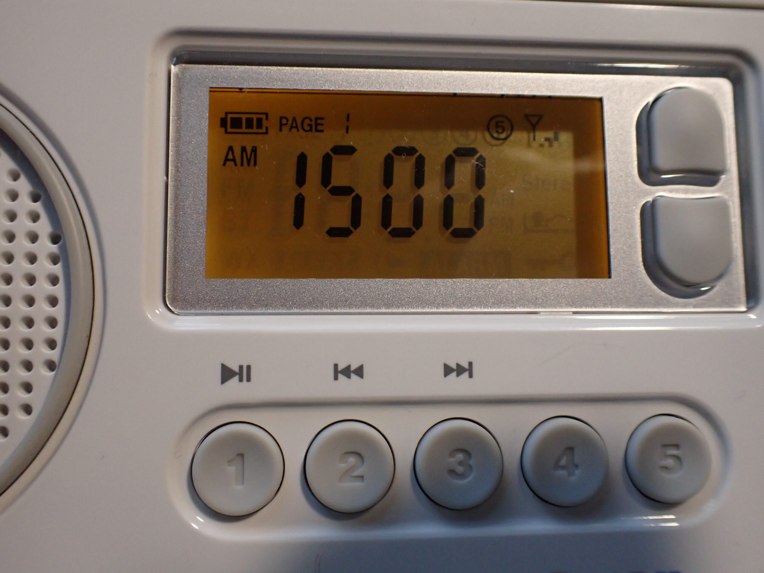
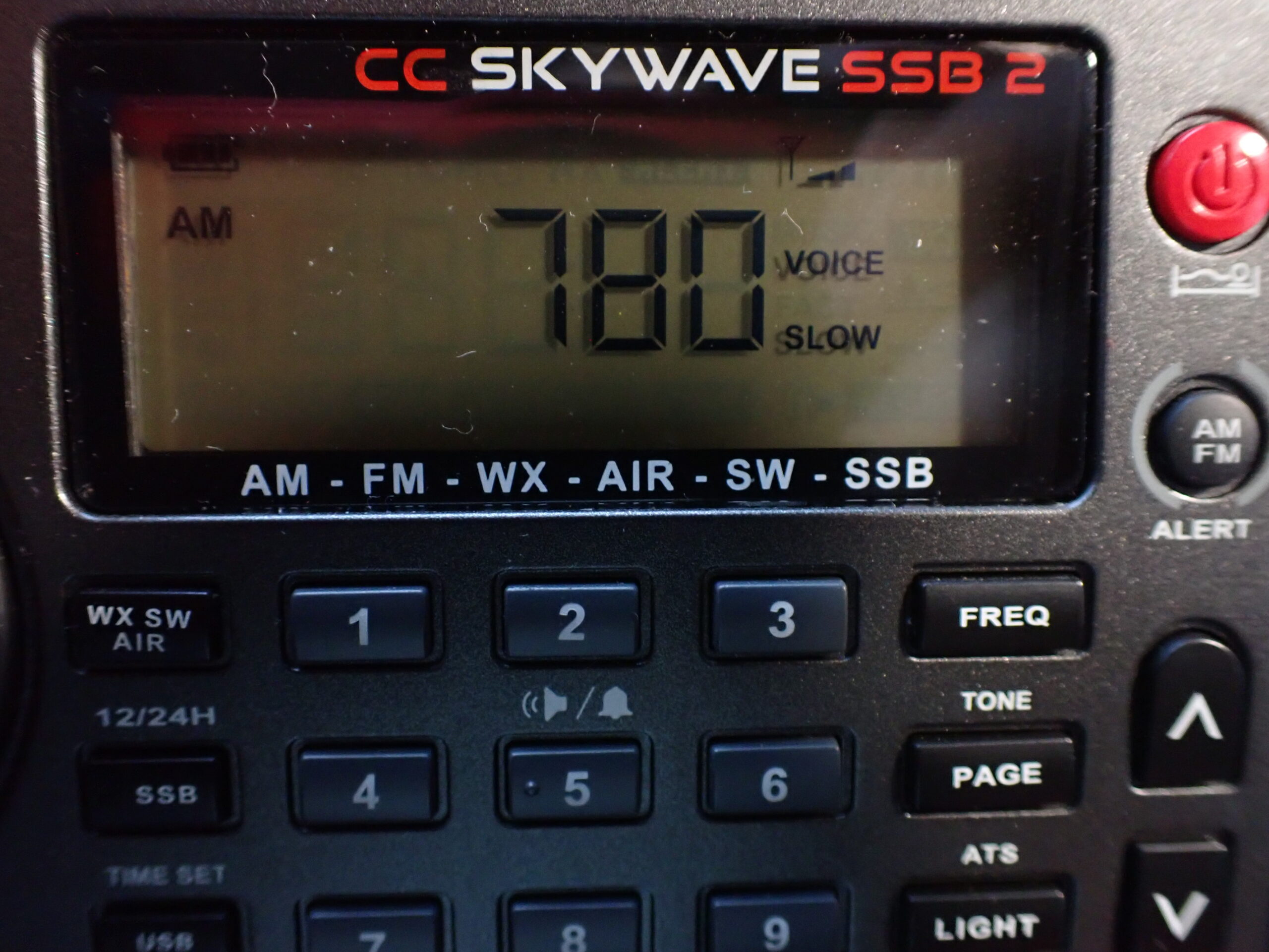
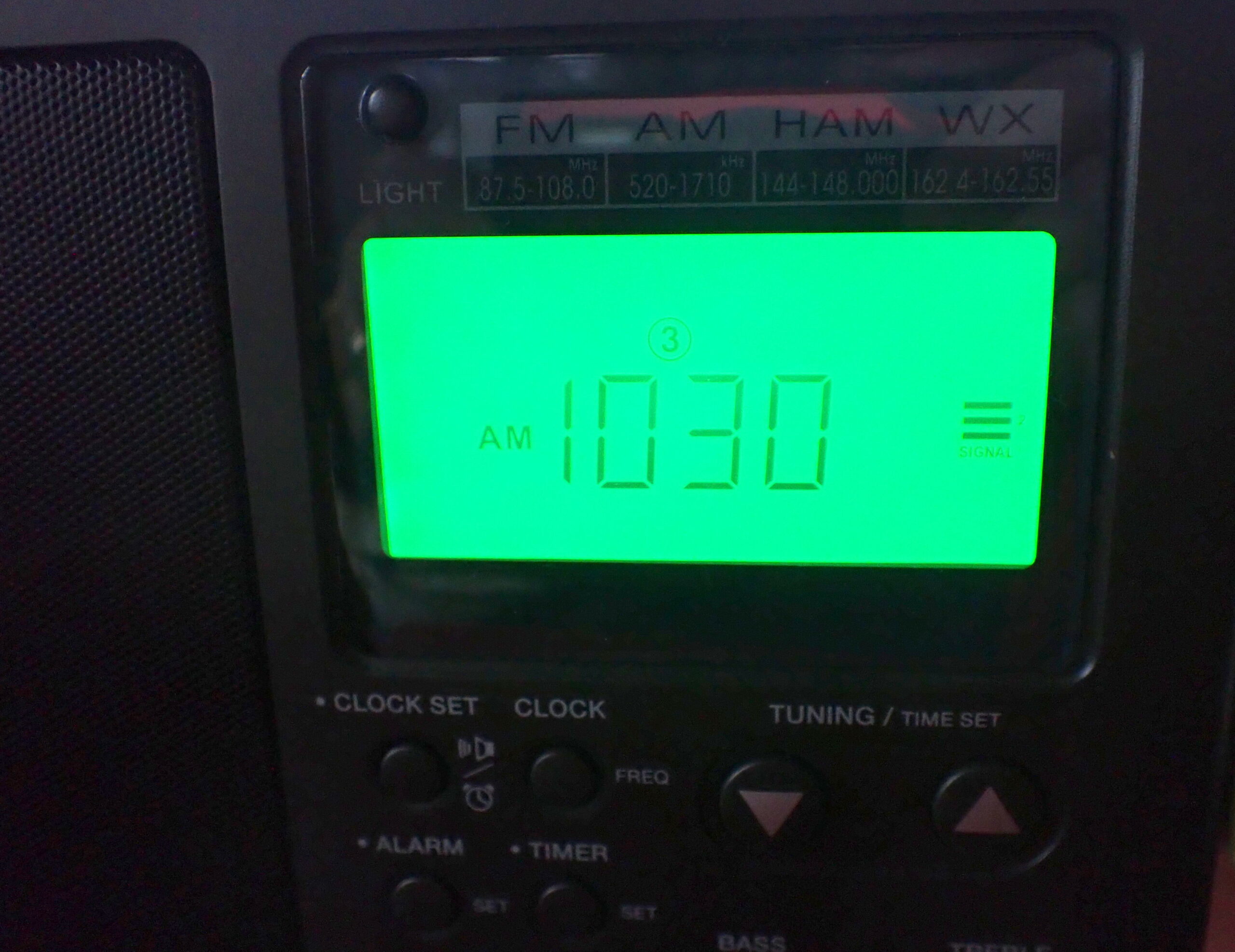
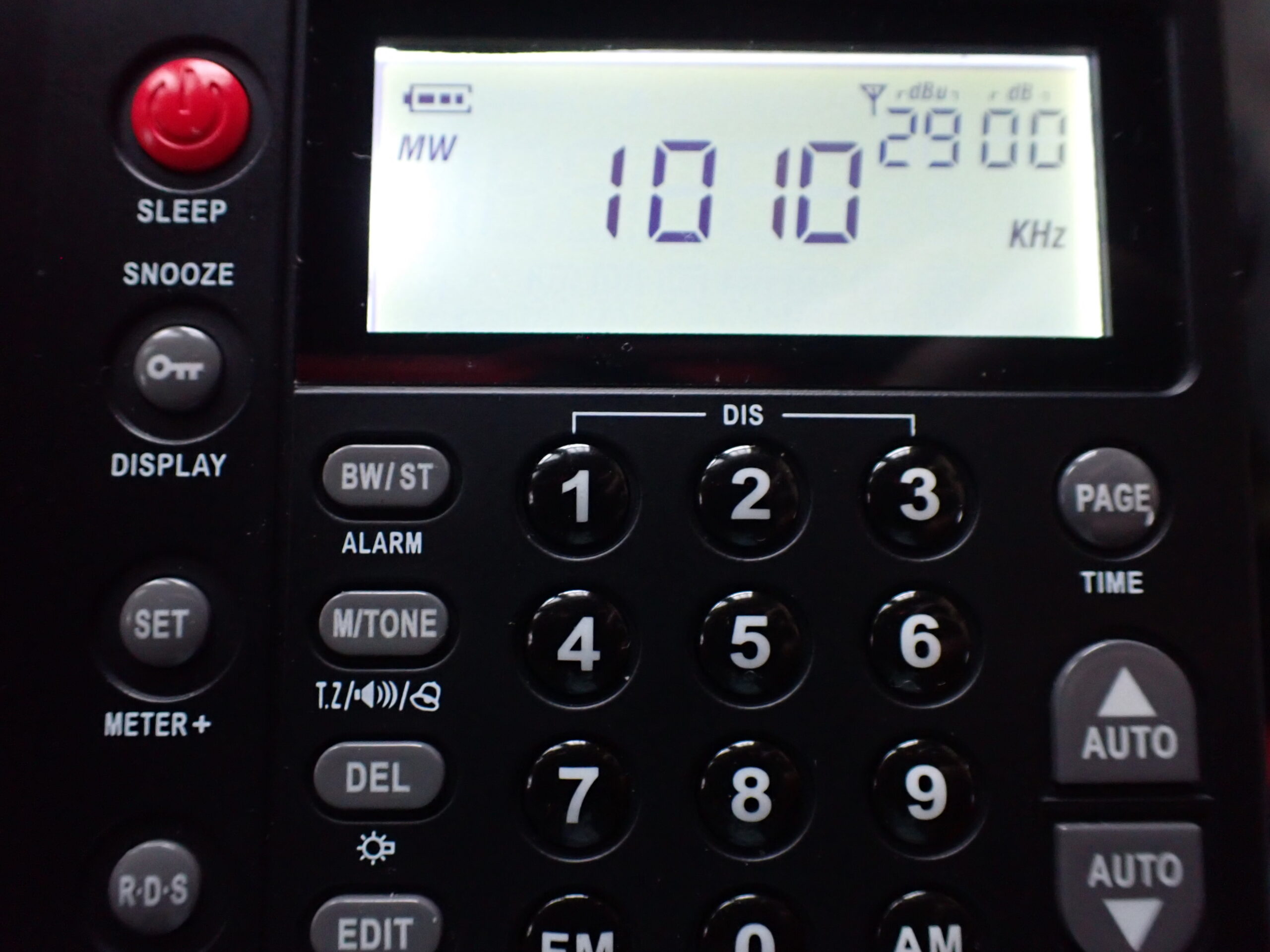
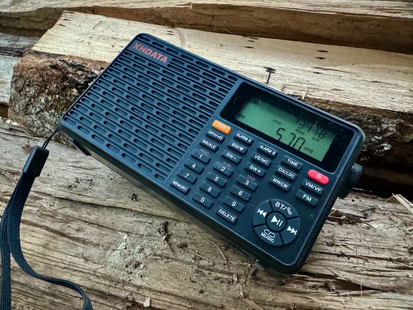
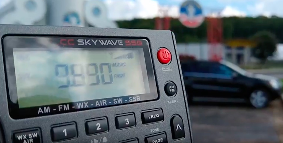
ECCC notes–on the same page as their announcement above–that over 90% of Canadians currently live within range of a Weatheradio transmitter, and that typical broadcast range is about 60 km (terrain, receiver quality, and antenna height can affect this). This network uses the familiar VHF weather frequencies in the 162 MHz range (including 162.400–162.550 MHz, depending on the transmitter)–the same frequencies used by NOAA in the US.
The Toronto Sun also picked up this news and notes that the service has been around for decades (launched in 1976, with a later upgrade in 2004 to include SAME-style alerting), and frames this as a significant change for Canadians who rely on weather radio for emergency alerting. Click here to read: https://torontosun.com/news/national/environment-canada-ending-weatherradio-forecast-service
Thomas’ Thoughts

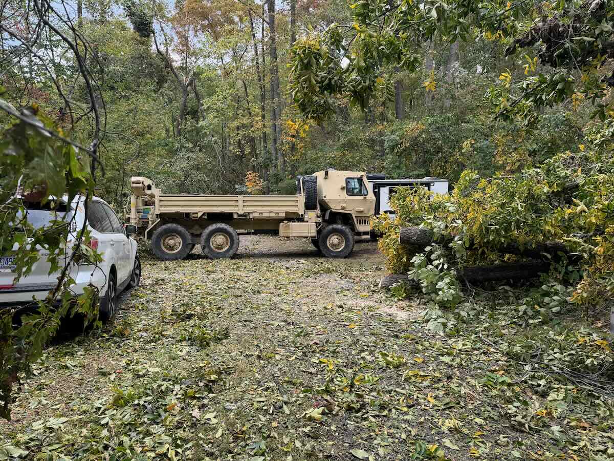
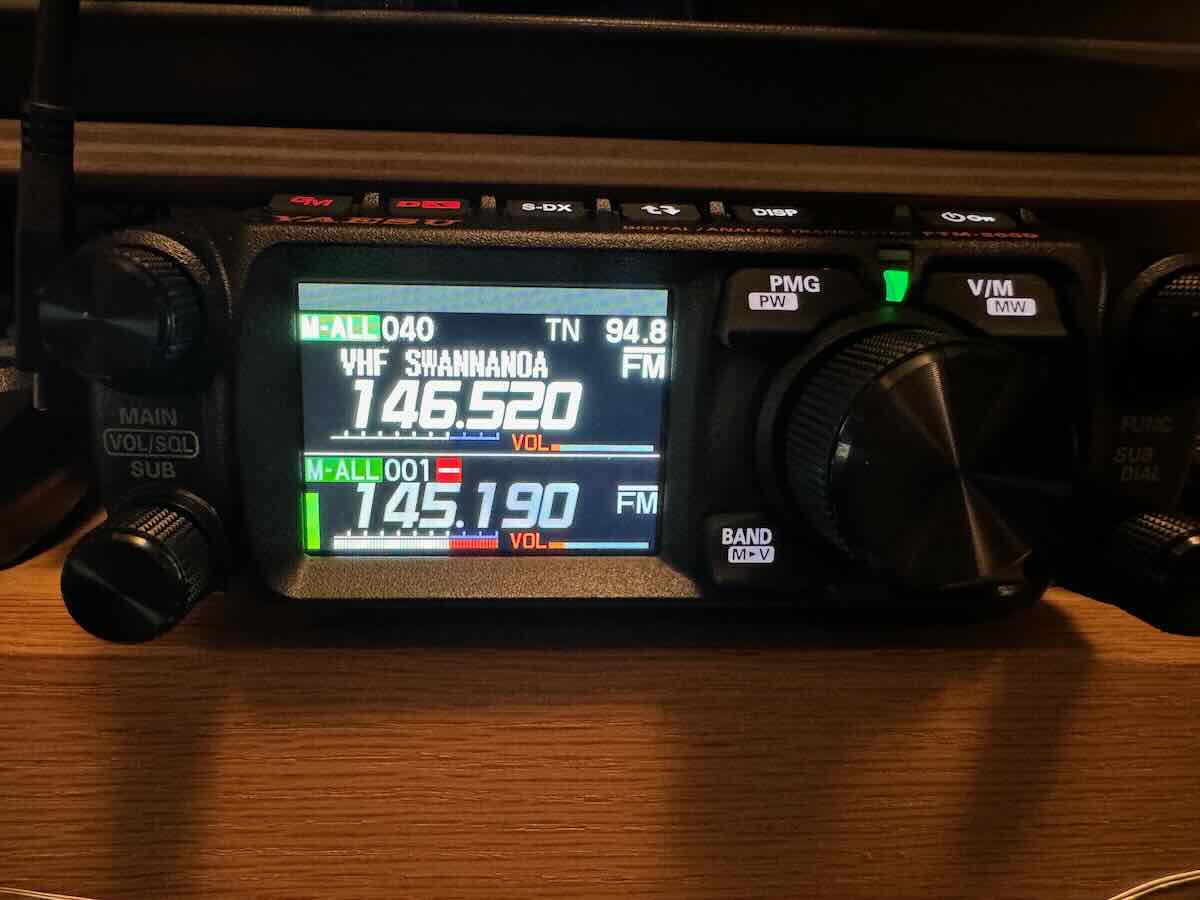
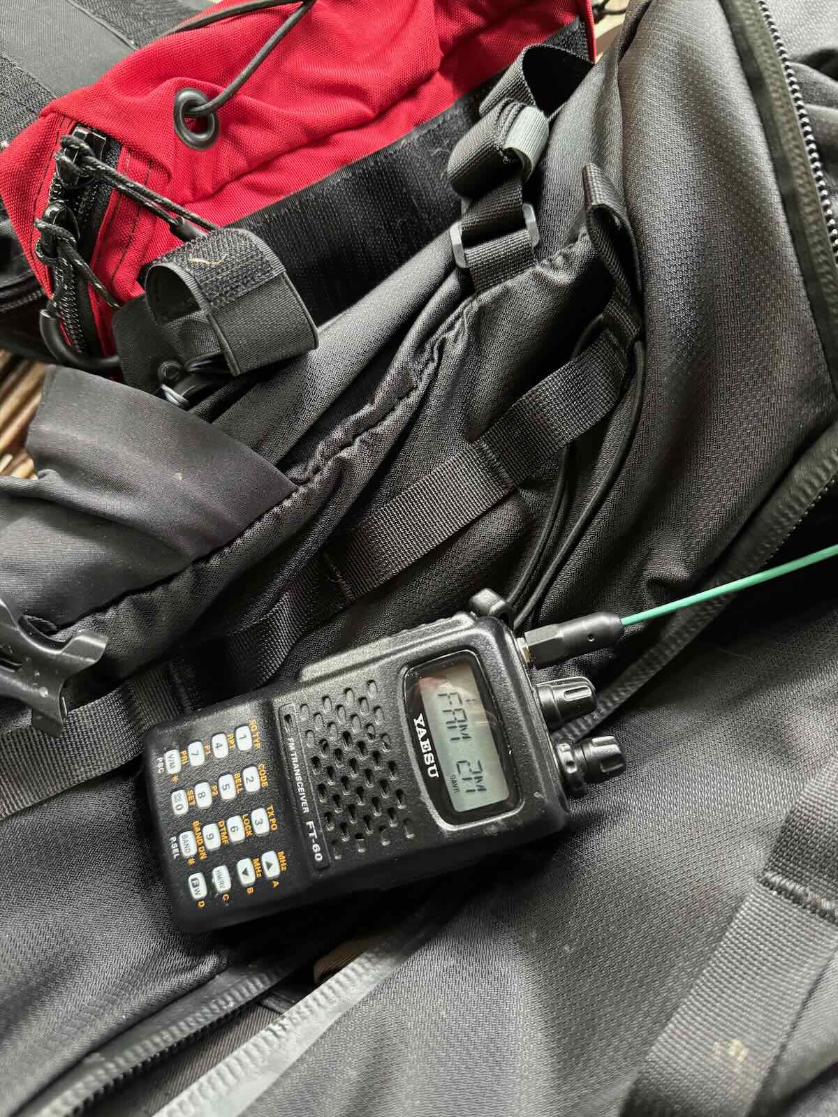
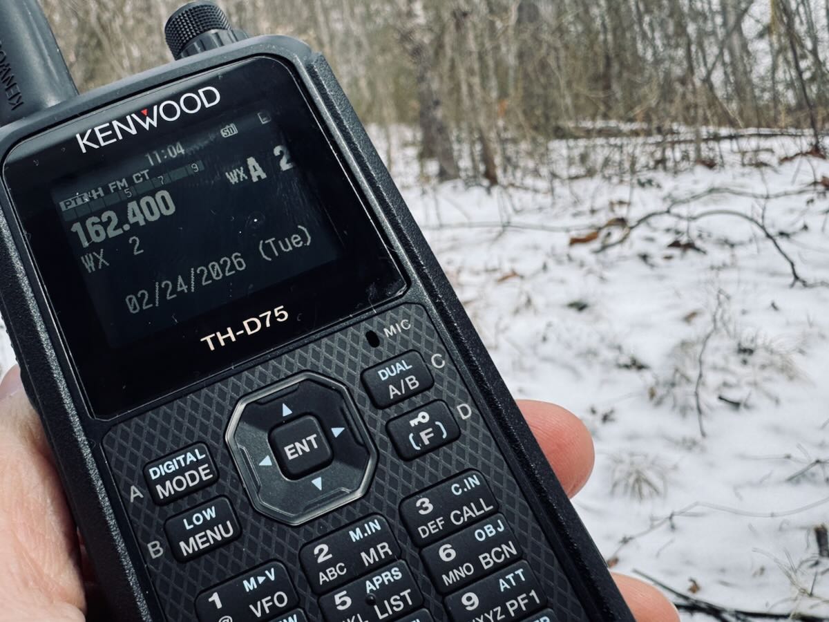
As we worked helping neighbors in our remote community in the aftermath of Hurricane Helene, we programmed NOAA Weather Radio on our handheld radios for reference.
I think this is a terrible idea—and I say that recognizing there are real costs involved in maintaining a nationwide radio network.
Relying only on online services for weather and alerting across a country as vast (and as frequently remote) as Canada feels short-sighted.
When a natural disaster hits (and it will) that’s exactly when internet access, cellular service, and even power can fail–and the “cost-benefit analysis” stops being theoretical.
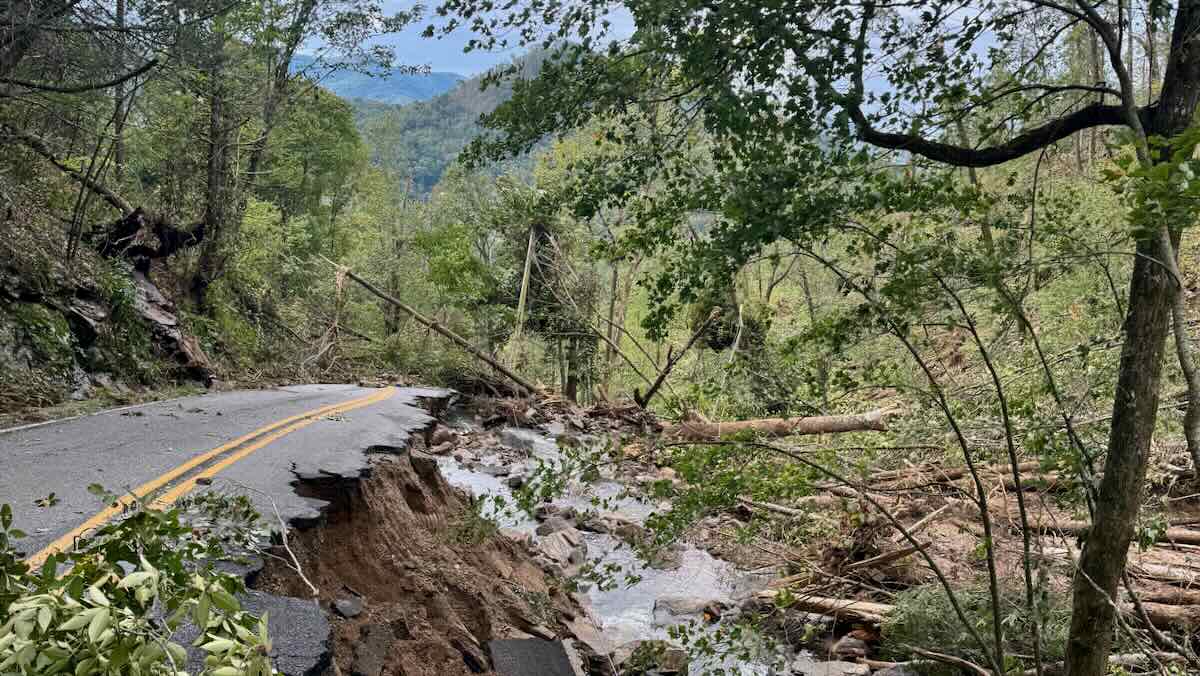
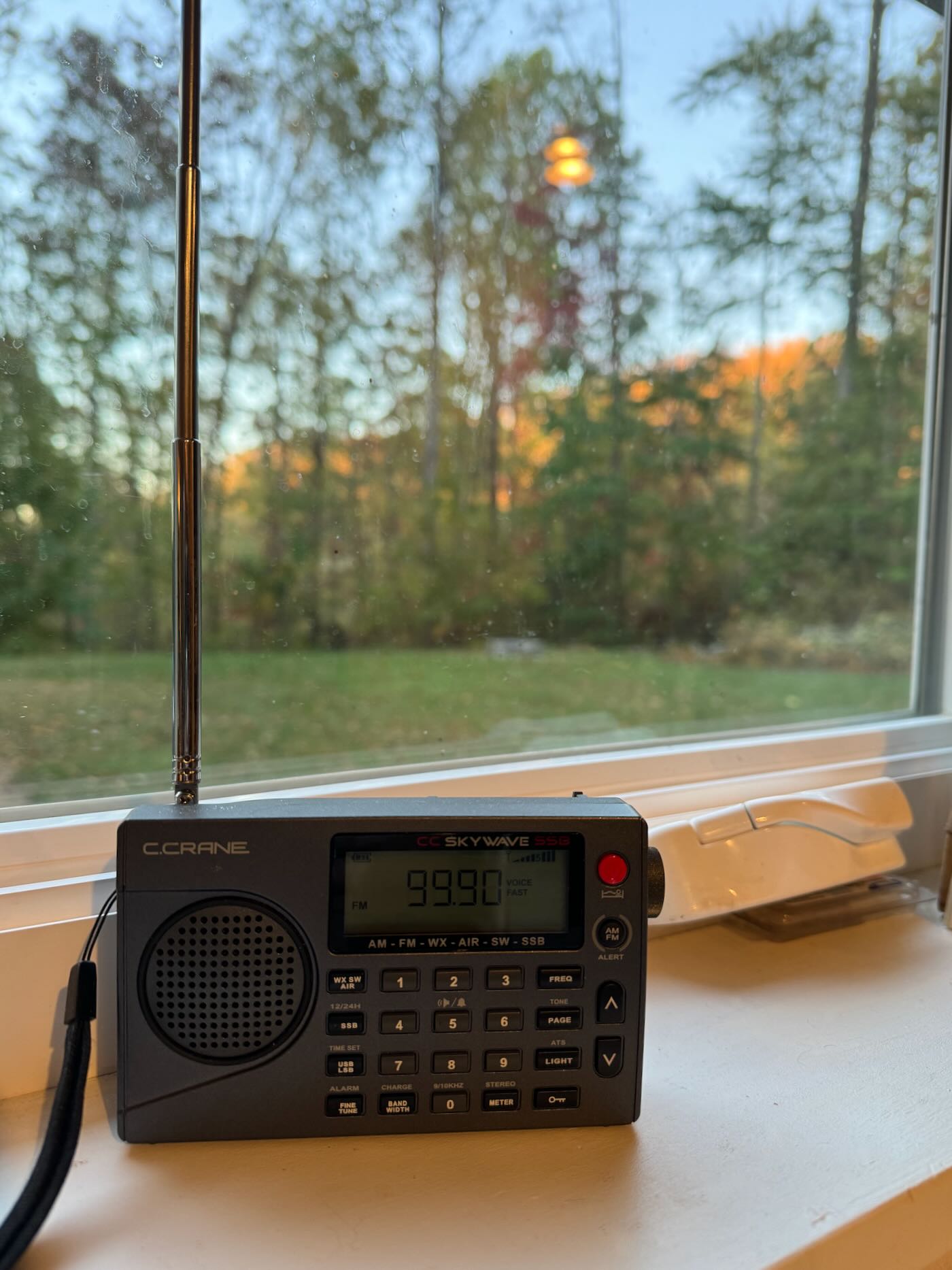
Many of you know, I was personally in the path of Hurricane Helene in North Carolina, and my community was without power and without reliable mobile data for three weeks. During that time, we relied heavily on NOAA Weather Radio to keep receiving forecasts and updates. That experience really drove home something many of us in the radio community already understand: sometimes you invest in systems not because they’re used every day, but because they can be life-saving when everything else breaks.
In my opinion, removing a resilient, one-to-many broadcast alerting resource like Weatheradio is poor management of taxpayer funds–not because it’s cheap, but because the value shows up when you need it most.
Canadians: Take Action Now
Here are two official channels I could find to ask for the Weatheradio shutdown decision to be reversed:
1) Contact your Member of Parliament (MP)
- Find your MP (by name or riding) and get their email/phone info here:
Find Members of Parliament - MP directory search (another entry point):
Current Members of Parliament – search - Mailing an MP is postage-free: you can address mail to
[Name of Member of Parliament]
House of Commons
Ottawa, Ontario
Canada K1A 0A610 - The House of Commons also maintains addresses/phone numbers for current MPs:
Addresses for current MPs
2) Contact the Minister responsible
The Weatheradio decision falls under Environment and Climate Change Canada (ECCC). Readers can also write directly to the Minister of Environment, Climate Change and Nature: The Honourable Julie Aviva Dabrusin.
Please comment if you have other suggestions about how to take action.