
AM bandwidth confusion: IF Filters today vs. yesterday
by 13dka
Whether or not a radio is a joy to listen to, or apt for difficult DX is decided to a large part by the last IF filter stage. Most radios of the past didn’t come with many IF filters to begin with, their quality varied a lot and harsh compromises had to be made in multi-purpose radios. With the advent of digital filtering and inexpensive DSP portables, we got spoiled by a rich choice of selectivity settings that came with an idiosyncrasy I had to wrap my head around first, namely a shift in how some (digital) filters are labeled now.
Bandwidth confusion
In AM mode both sidebands contain the same modulation information, meaning the audio bandwidth fitting into a 9kHz (region 1 and 3) or 10kHz (region 2) medium wave channel is approx. 1/2 of the modulation bandwidth – that’s 4.5 or 5 kHz. On shortwave, the 5kHz channel spacing is good for only 2.5kHz of audio spectrum.
Physical IF filters are specified by their entire (IF-) passband, not the audio passband. To enjoy the full audio spectrum an AM station can (usually) transmit, you need a 10kHz wide filter on the US medium wave (9kHz in the rest of the world), or a 5 kHz filter on shortwave. The more seasoned SWLs and hams among us are very used to that scheme, hence the prospect of a digital filter offering a maximum of only “6kHz” bandwidth or even less appears disappointing, even though that was the standard “wide” filter on many SWL tabletops and portables of the past..
When I got my first typical (Silicon Labs 473x-) DSP portable I started wondering about the filter choices: The widest filter setting showed familiar “6 kHz” in the display but it sounded so much wider than that! Checking the audio spectrum, I could see that the “6kHz” filter had full 6 kHz of audio bandwidth, with the other filter settings following that scheme. In other words, the settings were named after the audio bandwidth or ‘per-sideband’ bandwidth and didn’t follow the customary analog filter descriptions, the “6kHz” filter setting is in fact equivalent to a 12kHz IF filter in the old spelling!
Likewise, the Belka (ultra-) ultraportables – although not built around a SiLabs DSP – use the “audio bandwidth” naming scheme too, with the widest filter being called “4kHz”. This would be the equivalent to an oldschool 8kHz IF filter and it’s actually even wider – but this naming convention occasionally leads to unnecessary concerns about “too narrow” filter choices in these radios.
On hardware radios the naming shift might be just a means of simplification, as far as I know restricted to SiLabs-based DSP portables and the Belka, but while some SDR softwares (SDR Sharp, SDR Uno) are using the conventional ‘IF bandwidth’ naming scheme, SDR Console is using ‘AF/per sideband’ again. No surprise that this is confusing – but luckily only in the double sideband modulation modes.
In SSB only one sideband is supposed to go through the filter at a time, that’s why the filter’s specified bandwidth is equal to the possible audio bandwidth anyway and the befuddling naming issue doesn’t exist.
Demonstration and practical (kind of) measurements on some radios
While trying to make screenshots to illustrate the issue, I had the idea to generally check the filters of my radios for their characteristics. In order to show that I needed to cheat a little: Rather than trying to measure filters I can’t access individually for analysis with equipment I don’t own, I merely analyzed the audio output of the radios. While this can show an approximation to the actual filter shape, this is including every signal change happening behind the filters, for example tone controls. Lacking a signal generator, I tuned the radios to a 10kHz wide DRM signal from Kuwait on 15110 kHz to give the radios a wide, actual signal and circumvent any level-based automatic bandwidth or noise reduction shenanigans the DSP radios might employ.
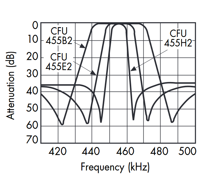
Tecsun PL-660
The PL-660 is unfortunately my only example of an (almost) oldschool analog portable, sporting 2 conventional, inexpensive ceramic filters of unknown specification and not using DSP for that. Their model numbers remind a bit of the MuRata filter codes but that doesn’t correspond with the results shown below, the “CXE455IU” could be the “wide” filter. However, at the end the difference between wide and narrow isn’t …umm… exactly dramatic:
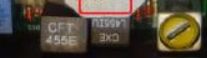
It looks like the passband is the same for both settings, just the skirts seem to drop a smidge faster in the narrow setting. The practical difference between the 2 settings is nothing to phone home about but certainly more noticeable in real life than the analyzer plot suggests, and also a frequent subject of complaint about later models of the PL-660. But the passband looks pretty good (flat), not too much of a drop-off until 2kHz, 3kHz is the the middle of the shoulder and the audio is ~12dB softer at this point.
XHDATA D-808
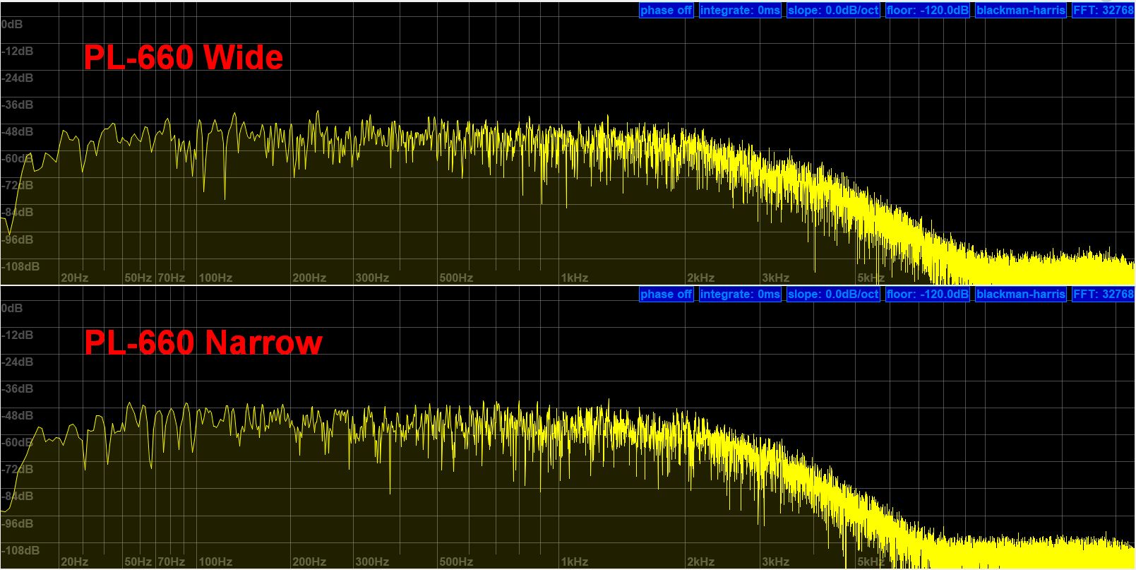
The D-808 is a great example for the bunch of small DSP-radios that save extensive (and expensive) additional circuitry and offer a particularly rich set of (audio-) passbands for AM, even very unusual ones like “1 kHz”.
D-808 at 6, 3 and 1kHz settings (audio/per-sideband bandwidth)
The passband is a little more sloped than that of the PL-660, but the tiny speaker likely keeps the impact of that in check. The big surprise is that the skirts are dropping so gently that even the PL-660’s ceramic filters seem to have a slightly better shape factor. I’m not sure if that is intentional or just a limitation of the Silicon Labs chips that these filters seem to mimic the shape of inexpensive ceramic filters, also in the next DSP radio in the group:
Tecsun S-8800
Given that this radio uses the same DSP chip in its 3rd IF stage, the difference in response is surprising: The slope within the passband is much more pronounced than that of the D-808 and 20 (audio-) decibels lower at the right/upper edge. The skirt is again surprisingly wide for a digital filter – both is also noticeable in the actual sound of that radio, often simultaneously a bit muffled and “too wide”.
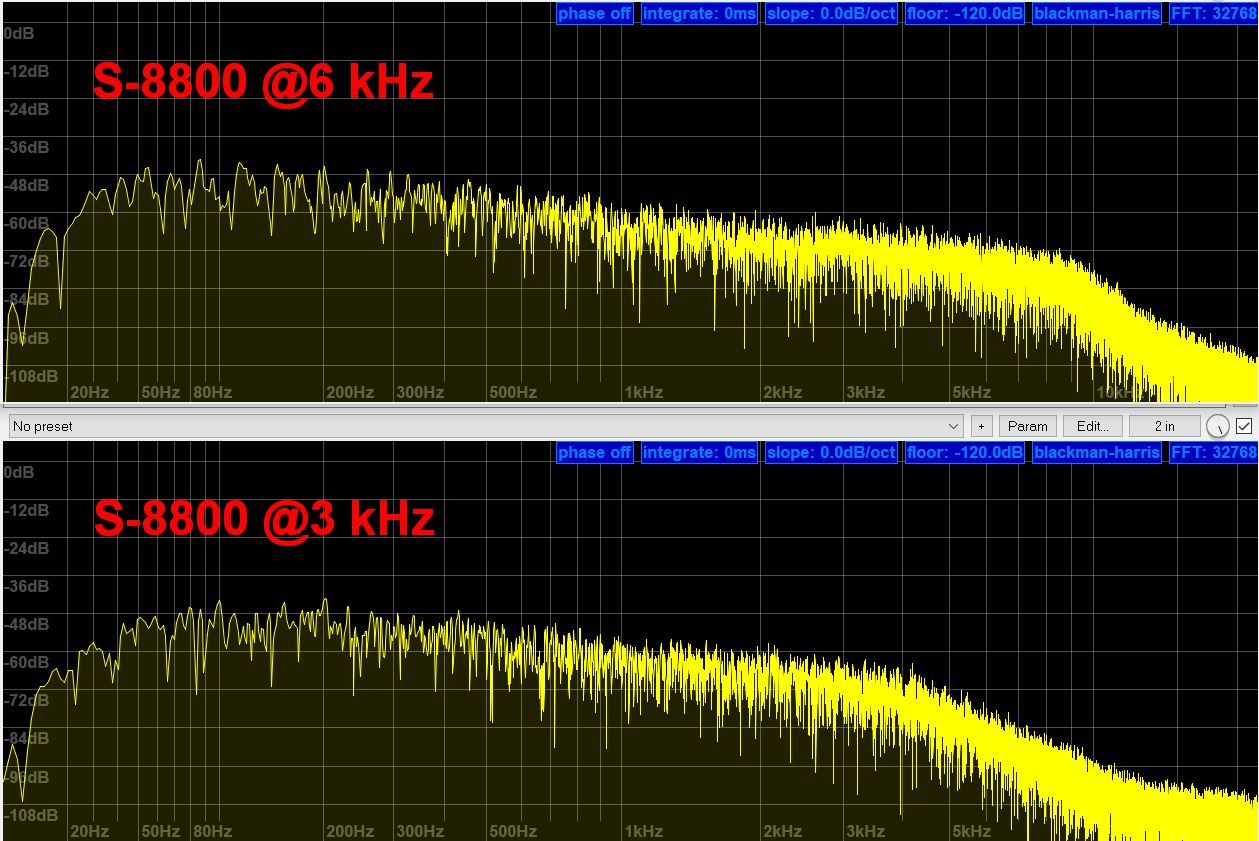
Tecsun S-8800 at 6 and 3 kHz filter settings
Belka vs. Icom IC-705
Please note that the IC-705 uses the “oldschool” (IF-) bandwidth specification scheme, while the Belka is “per sideband”. Since both radios allow setting the lower/left skirt individually, I deliberately left the lower cutoff frequency at their lowest settings on both (I like to hear the bass in both voice and music!). Unlike the DSP portables, the right/upper shoulders are what I’d expect from an “ideal” digital filter.
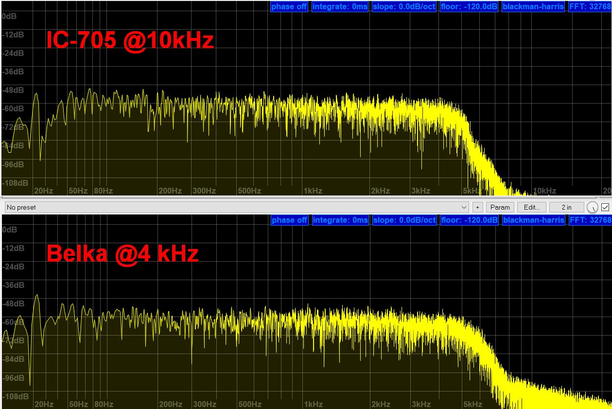
Top: IC-05 at full 10kHz IF bandwidth – Bottom: Belka at “4kHz”
The plot above also shows that the “4kHz” setting on the Belka is actually a bit wider than that, the Icom rolls off at 5kHz and the Belka at 4.5kHz (matching the European 9kHz MW channel spacing perfectly). In fact, all the bandwidths are tweaked 500Hz to 1kHz wider than the display suggests on the Belka, to fit the requirements of AM reception better. In SSB the displayed values are correct, it just doesn’t have separate display symbols for AM.
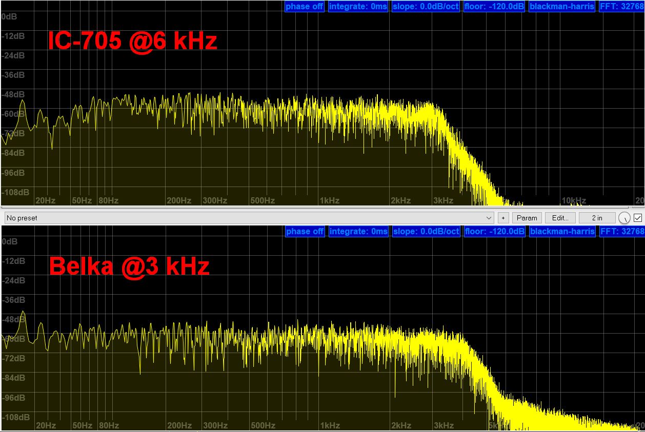
Top: IC-705 at the typical 6kHz “wide” filter setting, audio bandwidth is 3kHz – Bottom: Belka set to its “3kHz” setting is actually 4 kHz wide.
Now here’s why the Belka still shows more noise in its stopband: I made these plots at home, using an antenna to receive a signal (in lieu of a signal generator)…and interference: What you see there are the nasty idle pulses of a PLC modem in the neighborhood, a super wide signal covering the entire shortwave (minus the ham bands). The reason why you don’t see this on the Icom is that it has a pretty effective and adjustable IF noise blanker set to keep these pulses in check. All the other radios lack a noise blanker, and this visual demonstration shows why I wish they had one.
However, the additional presence of a true wideband signal was a good thing because I didn’t really think this through – the test signal should’ve been wider than the widest to-be-tested filter in first place. But all of the plots still tell their story, even when a small portion of the stopband noise seen on the other radios is caused by these pulses.
Extra-wide filters — nonessential but nice to have?
Besides the failed or semi-failed efforts to enhance and revitalize analog medium wave broadcasting – some AM stations exceed their allocated channel bandwidth (deliberately or not) and potentially have a little crispier audio, there are also experimental AM mode transmissions up to 32kHz wide on shortwave, all reasons why the demand for wide AM IF filters may have increased beyond the wish for best fidelity on standard medium wave.
The issue with wider-than-necessary filters (or filter settings) is that they do more harm than benefit on stations with a regular modulation bandwidth conforming to the standards. A slightly wider (or bad) filter can utilize the little extra bandwidth some stations claim for themselves and never sound dull, but they cannot produce treble that the station doesn’t transmit in first place, which seems to be a pretty common oversight. The surplus IF filter bandwidth will then only add noise/hiss and potentially adjacent channel interference, not fidelity.
However, the few actual wideband AM transmissions I have heard in my neck of the woods were quite impressive:
1. Radio China International is or was (to my knowledge) the only shortwave broadcaster doing experimental extra-wide (up to 32 kHz) transmissions on a somewhat regular basis.
2. Radio Romania Actualite is doing 16 kHz transmissions on medium wave 1152 kHz, basically occupying two Region 1-channels of 9kHz, leaving a little space left and right. They do that with 400kW (8 times the legal power of a Class-A station in the US) and the result is…niiiice:
This is an early evening signal from 820 miles away, almost sounding like an FM station next door! That almost makes me wish my favorite station would do that too! However, would these quite rare exceptions warrant buying a radio (meaning an SDR) for that?
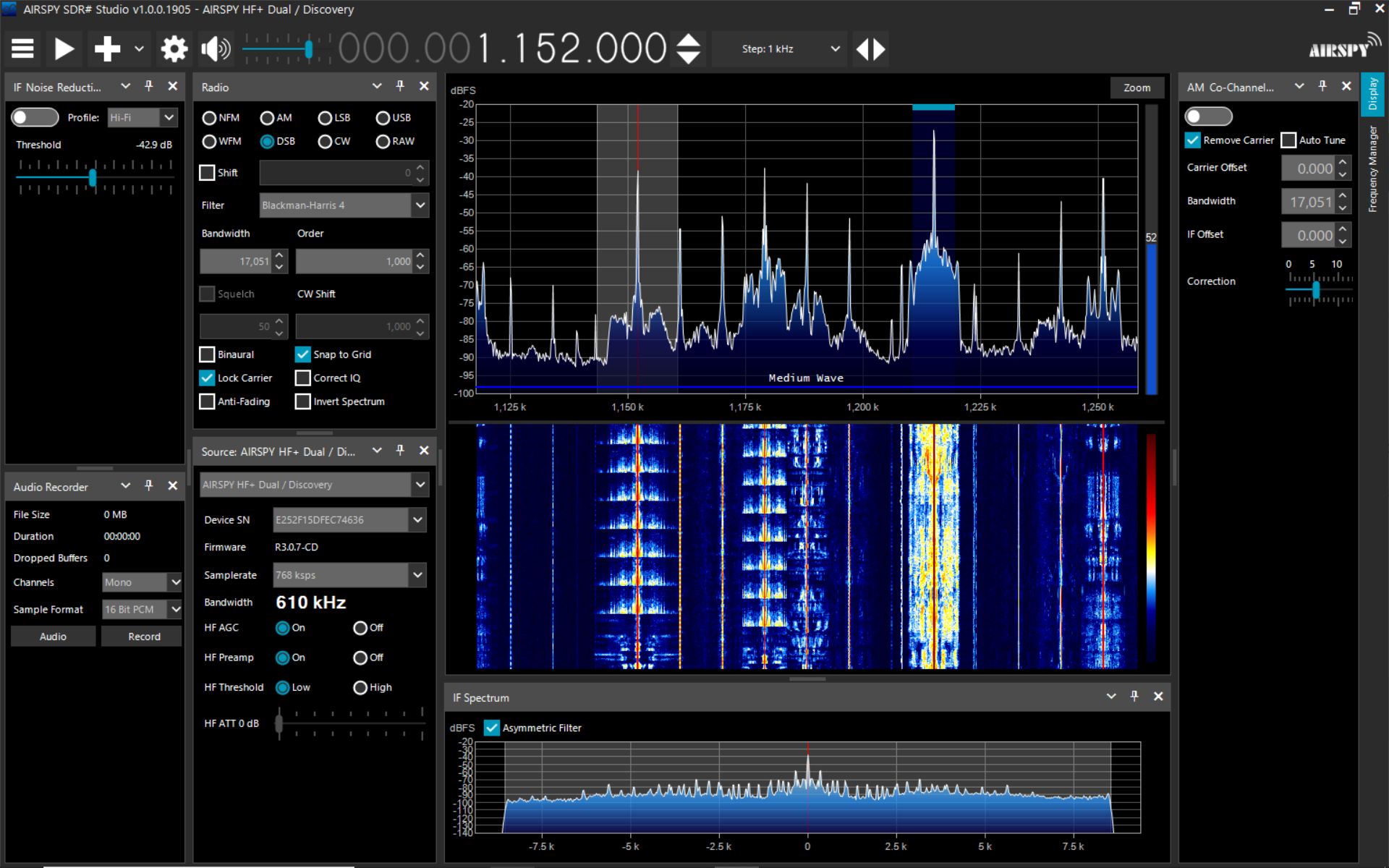
SDR# receiving 16kHz wide broadcast on 1152kHz (AirSpy HF+ Discovery)
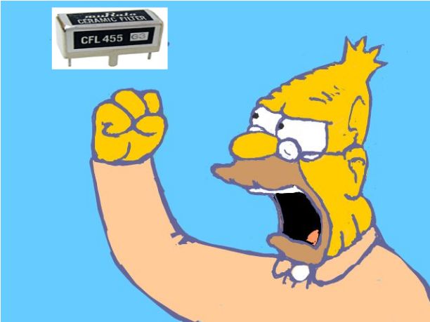
Old man waves fist at… compromise filters
With the important parts of this post being said (you may skip the following oldtimer’s ramblings) – I couldn’t help remembering once again how good we have it today, well, at least in terms of IF filters:
It almost feels like yesterday that many classic general coverage receivers and most multiband portables had at best 2 (ceramic) filters with compromise bandwidths to do something useful in the shortwave 5 kHz channel spacing, in the MW 9 or 10 kHz channel spacing and on SSB. The “narrow” filter had to do for both SSB and narrow AM, so 3kHz was chosen on some radios to fit both of these purposes equally mediocre and – on the majority of all SWL radios – a 6kHz “wide” filter (meant to fit a clean 5kHz shortwave channel) had to suffice for medium wave as well.
Few of the more expensive tabletops also came with a 12kHz wide filter, the Kenwood R-1000 and Yaesu FRG-7700 are probably the best known examples, curiously their siblings R-2000/5000 or the FRG-8800 didn’t. As far as I can tell, none of the classic Icoms provided filters for what could be considered only really beneficial for local medium wave station reception anyway, but the JRC radios beginning with the NRD-505 did. This list may not be complete but it already covers most of them – medium wave audio fidelity or wideband digital shenanigans were not considered important enough by most manufacturers of SWL radios.
Since the provided filters were not always fully satisfying even for their intended main purpose either, aftermarket filter modification kits were quite popular back in the day, a bunch of dealers even sold readily modified versions of popular radios.
My favorite example of a radio that had to make due with only one filter is the Yaesu FRG-7, which was shipped with a ceramic filter specified with 6kHz (-6dB) bandwidth extending to 14kHz on the odd ‘-50dB’ stopband mark. In reality this specification turned out quite enthusiastic, that and the fairly big speaker gave the FRG-7 its reputation for rich audio …and awful selectivity. The same filter had to do on medium wave, shortwave and SSB, which then often covered 2 adjacent 3kHz SSB channels at once, with potential to have the chipmunks from 3kHz above/below completely drowning out the station you wanted to hear. That’s why many of the “frogs” were modified with one of the filter modification kits offered by several companies, the most popular probably being the kit offered by Gilfer in New Jersey.
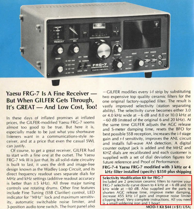
Gilfer modified FRG-7 and modification kit advertisement
Probably needless to say how amazing it seems in the light of the “we had nothing and had to push that uphill both ways” boomer lecture above, that even the most inexpensive DSP radios come with 5 different filter settings equivalent to 2, 4, 6, 8 and 12 kHz wide ceramic filters. My rudimentary analysis may confirm the perception that their digital replacements are not necessarily better, but none of the (digital) radios leaves you without a filter wide enough for best listening comfort on MW and SW, and several narrow ones to manage difficult reception conditions.
Further reading
To keep the size of this post in check, I didn’t add a section to pick up newcomers and explain IF filter basics and details in depth. A good, short primer can be found e.g. here, a good explanation of terms like “shape factor” can be found here and if you want to dig into this more, here’s a blast from the past (1969).
Thank you 13DKA for taking the time and effort on that excellent article.
Your results confirm my impressions on the multiple bandwidths of the Sangean PRD4W and the Tecsun PL360. They are useful at times, but the “skirt slopes” are unfortunately not steep.
Is there a Digital Radio with impressive digital Bandwidth filter skirts?
A few months ago for $20 I bought a used Sony XDR-S10HDiP, a first generation Apple iPod music player that can also pick up HD AM/FM radio transmissions.
I had read that it had the same chip inside as several other Sony HD radio models, such as their now legendary XDR FM tuner. For an AM antenna I am using a vintage Selec-A-tenna instead of the OEM Sony simple loop.
The AM section of this radio on a chip is impressive, including its bandwidth filter’s ability to separate a 5 miles away from me, 5000 Watt station on 590 kHz whose modulation is a sloppy wide 10 kHz,
from a 93 mile away from me 5000 Watt station on 600 kHz.
As an additional challenge there is a 3 miles away from me 5000 Watt station on 630 kHz.
The above situation is so challenging I use the 590/600 as a test for rating radios. Usually even the best radios cannot separate those two stations, and I typically have to drive 30 miles away from the antenna of the 590 kHz station, at a location where I can aim the null off the end of the ferrite loop stick antenna toward the 590 station, with the broadside maximum reception of the ferrite loop stick pointing toward the 600 kHz station.
Another aside about this Sony chip’s abilities sensitivity wise, is that in the early morning hours near sunrise, with Selec-A-Tenna pointed WSW direction toward 820 kHz WBAP 460 miles away, and where it is picking up a great signal, the Sony XDR-S10HDiP speaker will suddenly go silent and the HD icon will start flashing indicating it is trying to lock on to the all digital AM HD signal from 820 kHz WWFD in Maryland about 250 miles away to the ENE direction. So far the HD lock on has never been successful, though.
Turning to “old fashioned ceramic filters” with good skirt slopes,
the best I have used are the 2 bandwidths of the Kiwa MAP sync unit.
I bought a MAP unit to improve the shortwave performance of an AOR 3000A receiver, one of the first so called “DC to Daylight“ radios.
Those two Kiwa filters are very good.
Kiwa used to sell “No Loss Filter” add-on boards that used multiple series filters and an on board amplifier to get steep skirts with no loss of dB.
How narrow does a filter need to be,
and how steep a skirt does a filter have to have,
to get good AM separation?
Jay Allen claims that despite having a single 5 kHz ceramic filter setting, the analog Sony ICF-EX5MK2 Radio style of sync detector chip with stable lock on, makes it
“one of the most selective AM Radios he has ever tested.”.
I do not own one of those so I cannot judge.
The original analog detector circuit “phase lock loop” version of the Sangean PR-D5
( you can visually identify these by two black dots below the volume control knob)
has a pretty good ceramic filter that appears to be about 4 kHz wide with steep skirts.
Anyone know a good EPROM programmer who could rewrite and reburn the code of the EPROM inside the original version of the Sangean PR-D5 so that the “European setting” would change from 9 kHz channel tuning spacing, to 1 kHz? It would be useful to tune the old PR-D5 one kHz at a click, like my (#amn) soft muted) PR-D15 can.
Thank you for your comment, Hank! First off, the DSP filters may not have a good shape factor, but there is always a narrower one available to trade sound quality for a bit more selectivity. It’s a compromise again, but then again these radios (well, most of them) are rather inexpensive. If you look at the last plot, you can see that the still relatively inexpensive (< $200) Belka receiver has a variable filter with much nicer skirts.
I've heard of the qualities of the Sony XDR series and watched a few videos but I was too much into the SW multiband type to consider one of those, besides them all being discontinued (?). Alas the inexpensive radio market seems to be all SiLabs chips now, but there is also the very promising TEF6686 MW/SW/FM (car) radio chip (sporting e.g. high sensitivity FM with variable FM bandwidth) now. Alas the portable radios implementing this chip are again only available on eBay or AliExpress, and SSB is not a thing yet on those.
If you ask me how narrow and steep a filter needs to be for good AM separation, well for maximum sound quality that would be 9kHz in Europe (and 5kHz for shortwave), or a little less for an extra safety margin in a crowded band, generally with a shape factor =/<2, which is achievable with ceramic filters. They are basically ladder filters anyway, you can cascade cheaper filters for increased stopband attenuation and skirt steepness as you described, instead of buying one more expensive filter with more "rungs" built-in, however this technology may be on its way out anyway. What you also want is a flat passband, some ripple is tolerable but this is what actually makes the sound of a filter. That all shouldn't be an issue with properly implemented digital filters though.
Hank,
.Are you sure that your problem is filtering? The local station is a multiple of 10 kHz away from the pair of weak stations. If the RF amplifier is overloaded by the local station it will produce lots of intermodulation products. This is the production not only f1+ f2, f1-f2, but also multiples and combinations of all of the frequencies involved. By moving away will reduce the effect of the strong signal.
Silicon Labs has been sold to https://www.skyworksinc.com/-/media/SkyWorks/SL/documents/public/data-shorts/Si4736-37-38-39-short.pdf
I note that it is the crudest filtering on their data sheet prior to the RF amplifier hence my comment. They make no claim as to selectivity. The Digital signal processing stage contains the filtering. It depends on the complexity of this chip as to how many pole filter is used.
The typical tuner IC does not output a tuning voltage that could control a varicap diode you could put in parallel with a tuning coil to reject all but the frequency displayed on the radio. The mechanical variable capacitor has disappeared in these radios.
The best solution is to turn the radio around to minimise the signal strength of the local station. This can be difficult without a signal strength meter, because the automatic gain control will maintain the volume as the signal strength reduces. Then use one of the tuned loop antennas mentioned on this site. That will allow you to increase the signal strength of the weak signals but not your local station because it is at a different frequency.
Software filters.
In a tuned filter using inductors and capacitors. The current in an inductor is delayed because it opposes the change in magnetic fields. The voltage across a capacitor is delayed as the charge changes. Ie there is delays.
In software filters the digitised signal is stored in memory in say 360 identical samples ie one per degree of the centre frequency. The memory is written and read out sequentially with an address offset which causes a delay. If there is an average delay in reading the memory, then reading previous sample is advanced like what happens in an capacitor and if the sample is after the average delay sample it is lagged like the inductor. Those advanced and delayed samples are either added or subtracted in the designed signal strength ratio. In other words simulating the inductors and capacitors. It is possible to design multipole filters with very steep sides at very low cost. Thus the same filter program is used, where and the variables are modified for different bandwidths.
Since in DSP receivers, the filtering is at base band, the bandwidth selected is the same number as the low pass filter prior to modulation in the transmitter. It is only in double sideband full carrier ie AM which doubles the transmitted bandwidth.
It is only where a band pass filter is specified by the centre frequency and the total width of passed. This is confusing for most so is better specified as the centre frequency,± frequency width of one side.
For example an FM signal is 200 kHz wide, but is not usually specified as ±100 kHz. This is why FM frequencies are 88.1, 88.3…. So the 88.1 MHz station uses from 88.0 – 88.2 and the next broadcaster is 88.2 – 88.4 MHz. Fortunately regulators have learnt not to overlap channels as occurs in the medium and low frequency AM bands.
It is only superhetrodyne receivers which have one or more intermediate frequencies. Ceramic filters and prior to that Inductive/capacitive tuned filters and in expensive receivers mechanical filters. All of these radios had variable tuned filter between the antenna and the frequency conversion to the IF. More expensive receivers had an RF amplifier followed by another variable tuned filter. Hence the triple ganged tuning capacitor. The third one for the local oscillator.
All DSP receivers work like the analog version of the homodyne. They mix the the signal from a local oscillator operating at the same frequency as the carrier or centre frequency of the transmission. Thus there is no intermediate frequency stage.
The intermodulation in the mixer causes the difference between the incoming carrier and the local oscillator signals to produce 0 Hz and the modulation will be at the same frequency prior to the transmitter. The local oscillator has 2 outputs 90° apart. These signals are digitised and a microprocessor will low pass filter the signal to the selected bandwidth. The signals are now demodulated to determine the amplitude and phase, which will demodulate analog and digital modulations.
The antenna input is connected to an automatically gain controlled attenuator to prevent overloading then an RF amplifier prior to downconversion.
The main advantages of the DSP technique is a wide tunable frequency range, the lack of frequency specific tuned circuits which reduces the cost and size and the lack of reception of false image frequencies which all occurs in a conventional superhetrodyne receiver.
Kudos also for a cogent review and testing of real world response curves. Old school ceramic filters usually had a “skirt selectivity” of around 2:1 to 3:1. A 4 kHz filter at -6 dB would have a -60 dB “skirt” of around 8 kHz up to 12 kHz depending on the quality of the ceramic filter. What distinguished the higher quality filters was something called “ultimate selectivity” measured at -100 dB down and the tighter the better, usually around 20 kHz wide.
Since digital filters work differently, it makes sense that in the presence of overloading, unsophisticated digital filters can be overwhelmed easier than a comparable old fashioned ceramic filter. Depends on the type. strength, and distance from the passband is the offending interference. It also confirms my suspicion about how my Tecsun S-8800 behaves when trying to get the audio to sound right. Thank you for your work on this topic!
Thank you, Tom! Yes, a shape factor clearly below 3 was already considered great and how the stopband looked far (like 20 or 50 kHz) above/below the center frequency was usually unknown for most consumer grade radios, but still a factor nonetheless. The initial version of the article was 3 times longer and was meant to contain a full breakdown of IF filter types and metrics but then I remembered why I wanted to write it in first place (the “bandwidth confusion”) and threw everything out. 🙂
Another amazing, informative post 13DKA!
You had me at “Old man waves fist at… compromise filters!” HA HA!!!
Thanks so much for sharing!
Cheers,
Thomas
Aw, thank you Thomas! I’m always glad to share knowledge I gained after everyone else did! 🙂