Many thanks to SWLing Post contributor, Giuseppe Morlè, who shares the following antenna project:
Dear Thomas and SWLing Post Friends ,
I’m Giuseppe Morlè, iz0gzw, from Central Italy, Formia on the Tyrrhenian Sea…
Some time ago I had drawn this minimal HF antenna on paper…
I took advantage of the New Year’s Eve rain to be able to build it with the usual leftover scraps…
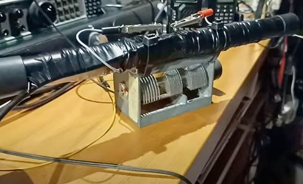
The system consists of a 35 cm tube with two separate windings of telephone cable on it, 2.5 m on each side, green and white…in the center I connected the 4 ends to X…
The green lead with the white and the white with the green to the variable capacitor and the other two leads to the RG58 cable that goes to the receiver.
I started the test and noticed that the agreement was possible from 7 to 21 MHz…
I then placed a long ferrite inside the tube…
I noticed a strengthening of the signal and consequently of the noise picked up and the chord dropped to 3.2 MHz.
Tests inside my shack showed decent reception on all ranges…in the evening on the balcony on 80 m. I could perfectly listen to a QSO between Italian stations.
Everything is still in the experimental phase and I think I will try this minimal system also in QRP transmission.
In this first video I explain how this minimal antenna is made:
The second video concerns a 20 meter test by car. The antenna is placed on the dashboard of the car inside:
In the third video, I explain how it works without the ferrite and with the ferrite inside the tube:
In this video you can see the test on 40 m. outdoors on the roof of the house:
The tests are carried out at home in order to understand what can be achieved in an environment that is difficult to receive.
I will do more outdoor tests and I think this small minimal antenna will receive better. I will keep you informed.
Thank you all for your attention and I wish you all a new year full of satisfaction.
’73 de Giuseppe iz0gzw.
Fascinating, Giuseppe! I love all of these brilliant little antennas you design out of your “junk” drawer! We look forward to hearing more about this antenna and any modifications you make to it!


Really interesting an a fun project, Guisippe 🙂
As I see it, it is a giant L/C tuned circuit, the coil is an inductor plus the capacitor. When the circuit is resonate with the infrequence of the receiver you hear the noise go up ( like tuning a “Magnetic loop”). Adding the ferrite core is changing the Impedance in the L/C circuit so moving the centre resonance.
Great job, I hope you can TX with it. it will be a great experiment.
Guisippe, can we see a schematic please? Thank you.
While specs suggest more like ~5MHz, loopsticks built with mix 61 ferrite rods can supposedly be good to over 7MHz. A schematic using an preamp stage to compensate for a relatively small ferrite rod:
http://www.jumaradio.com/active-ferrite-rod-antenna/active-ferrite-rod-antenna.html
https://youtu.be/tNjh_ebqCOA?si=s-kM3k1mrmknypvV
Thanks my friend.
73. Giuseppe iz0gzw.
https://youtu.be/tNjh_ebqCOA?si=s-kM3k1mrmknypvV
Thanks my friend.
73.Giuseppe iz0gzw.