By Jock Elliott, KB2GOM
It was this post by Alan — https://swling.com/blog/2024/11/bbc-rd-how-to-test-a-loop-antenna/ — that set me off. After downloading the BBC report on how to test a loop antenna, I noticed the following in it:
“Polarisation Illustrations of the antenna usually show it mounted upright; that is, with
its axis parallel to the ground. This is fine for the reception of LF and MF transmissions, which
are vertically polarised, but most HF transmissions are horizontally polarised.”
Huh, I thought, “I wonder this would have any bearing on how I use my MFJ 1886 loop antenna?
So hooking the 1886 loop to an SDRplay RSPdx, here’s what the spectrum looks like on medium wave in vertical orientation with the 1886’s internal amp turned on:
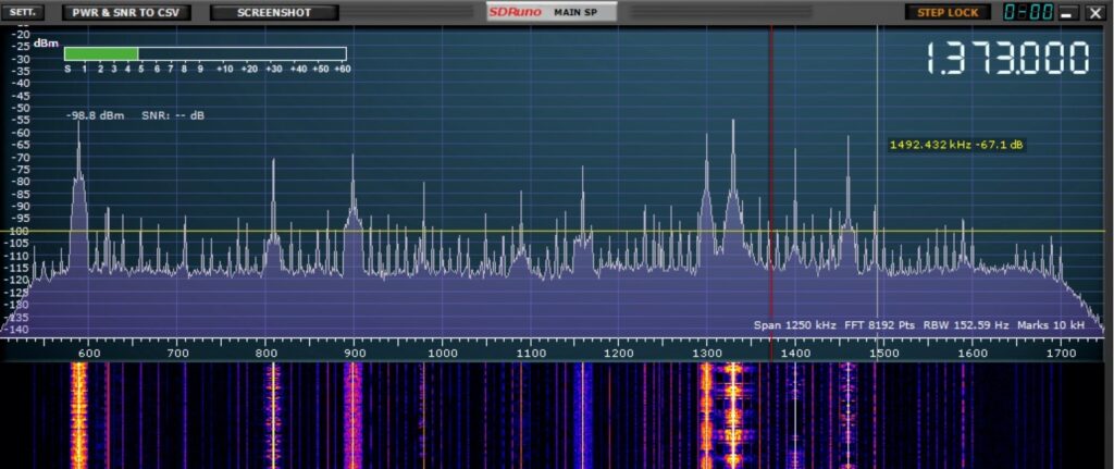 And here’s what the medium wave spectrum looks like with the loop in horizontal orientation, amp on:
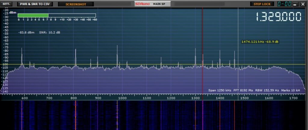 But what about shortwave reception? Here’s 31 meters in vertical orientation:
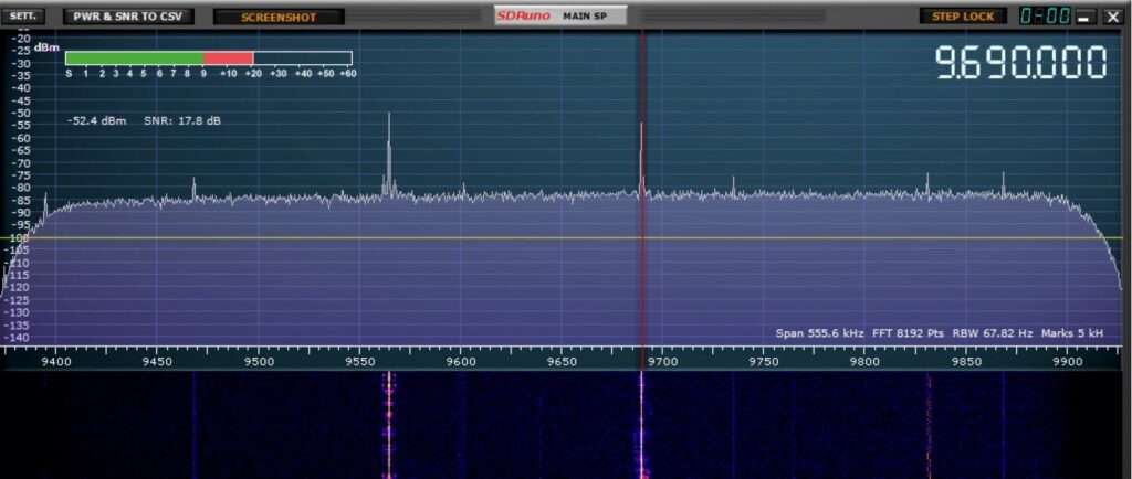 And here’s 31 meters with the loop in horizontal orientation:
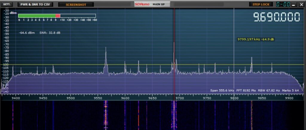 Here’s 25 meters in vertical orientation:
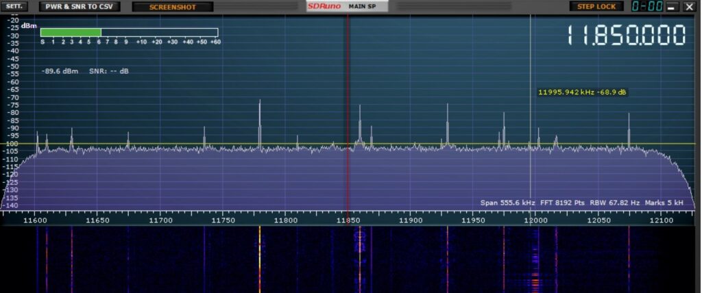 Here’s 25 meters in horizontal orientation:
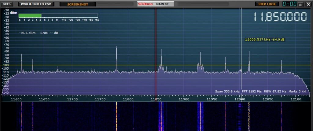 It looks to me, at the very least, the noise floor is lower . . . or I am in desperate need of a laxative?
For more about my adventures with the 1886 loop, check this — https://swling.com/blog/2022/10/testing-the-mfj-1886-receive-loop-antenna/ — and this — https://swling.com/blog/2023/01/saturday-morning-fun-fat-mw-dxing-with-the-mfj-1886/
My conclusions: I definitely don’t want the 1886 loop in horizontal orientation for medium wave DXing, but I think that the flat orientation might help for shortwave DXing.
What do you think?

I’m confused. When I read the main article, I thought I understood the difference between the loop being vertical and the loop being horizontal. But after reading the comments, I am confused again. After 71 years revolving around on this planet I have learned that my confusion often comes from a lack of understanding the vocabulary. Although I’ve been involved in SWL off and on since I was a kid, I’m always seeing in these posts terminology that I simple do not know. Pictures, I need pictures. Could someone post a very simple photo of vertical vs horizontal orientation? Pretty please. Thank you for this fine blog and Happy Ho-Hos to you all.
J
John,
I don’t know how to post photos in the comments, but here’s the short answer to your question:
With the loop oriented vertically, it stands with the flat side straight up and down, like a car wheel.
When oriented horizontally, the flat side lays “on the ground” like a pizza.
Does that help?
Cheers, Jock
Great! That’s how I understood it. Many thanks. Pizza…now I’m hungry ?
Hi Jock,
Small receving loops with their axis parallel to the ground (i.e. the loop is vertical) display vertical polarity at low elevation angles. So that is great for signals like ground wave AM broadcast stations and near field noise. At these low angles, the nulls can be very sharp in a well designed loop. As the angle of arrival of signals increase (ionospherically propagated signals) the loop begins to display a horizontally polarized component and nulls become shallow). For NVIS signals (very high angle of arrival) the small loop is essentially omnidirectional and horizontally polarized. A quick stroll through any of the NEC modelling programs will verify this.
Dale W4OP
Thanks Dale!
Cheers, Jock
Hi Jock,
Interesting tests! I will have to concur with Bob – if I may state it another way, there is no “proper” position for a loop when getting shortwave signals.
From my study of propagation over the years, polarization is nice when talking about theory in a lab or a controlled environment, and does indeed generally work with MW signals since they are “relatively” close, but once a signal starts traveling major distances, especially shortwave (and amateur) signals, the horizontal/vertical polarization issue becomes much less identifiable due to reflections off the ground, the ionosphere, even patches of ionization clouds.
Signals in the HF range, as of course you know, are dependent on reflection/refraction of the various F1 and F2 layers (and combined at night), and except under special circumstances, are absorbed by the D and E layers. All of that bouncing takes it’s toll on the polarization.
One other thing I have noted since doing a lot of Digital work (FT8, FT4, Meteor Scatter etc.) which also applies to polarization, is that the theory of reciprocity of signals is just that – more theory than reality. I learned the theory like all amateurs did during their licensing tests, but weak signal digital modes have shown very clearly there is actually very little reciprocity between stations. Another way of saying this is, the atmosphere is a cruel mistress, who can understand her?!
I guess this is a long-winded way of saying one has to find the best position for a loop antenna on shortwave for each signal received. There may be patterns which emerge as you gather data for your particular location, but that is more likely an indication of your surround logistics and the effect your surroundings have on an incoming signal rather than the signal’s originating polarization. Just my 2-cents worth!
Cheers! Robert K4PKM
Robert,
“Another way of saying this is, the atmosphere is a cruel mistress, who can understand her?!”
Indeed!
In fact, if I had been a little smarter, I would have remembered this post of mine — https://swling.com/blog/2023/10/the-weirdest-shortwave-tuning-technique/ — in which I found that waving the whip antenna on a portable to different orientations can make a big difference in being able to copy a signal.
So of course it makes sense that moving the loop into different positions might be necessary for optimal reception of a particular signal.
I suppose the ultimate setup might be an articulated motorized outdoor mount with a joystick inside that would allow me to fiddle the loop to the optimal position.
Cheers, Jock
I remember enjoying that post! I think you are on to something, especially with a joystick for full articulation. I hope you share the prototype design with us!! That would be a money-maker!!
To me, it does seem that performance is indeed better in the horizontal position on shortwave. I don’t think any laxatives are in order on this one!
Rob
Rob,”
” I don’t think any laxatives are in order on this one!”
That’s a relief! (grin)
Cheers, Jock
Hi Jock,
Excellent! I’ve not tried your horizontal experiment on shortwave, then viewing the results on the SDR spectrum. The resulting improvement is dramatic.
Looking at your images, you’ve got not only lower noise floor but greater signal too. And better SNR of course. I’ll be using this method on SW. Thanks!
Bill, WE7W
Bill,
Thanks for the kind words.
Cheers, Jock
As a retired radio engineer, I would say, believe what you just measured!
The spectrum plots show what you get at your location!
Yes, MW stations are typically just a vertical tower, so are vertically polarized. So your loop will do well receiving MW when it is vertical. When you move your loop to be horizontal, it is not good for receiving the vertically polarized MW signals. Also, any receive antenna with horizontal polarization is much more susceptible to radio hash emitted from power lines nearby. That’s why the noise floor is so much higher. So you definitely want to go with vertical polarization on your loop when receiving MW signals.
As for the HF signals, the 31m result with vertical antenna sure has a high noise floor. But that, apparently, is just what you get at your location. Even so, the S/N is better with horizontal polarization on 31m and 25m. So use the horizontal polarization for those bands.
I think your results are very revealing. Thanks for the post!
– Steve (W4OGM)
Steve,
Thanks for the kind words and your expertise.
Cheers, Jock
Hi Jock,
To address your conundrum, from my long-standing, untutored tinkering with loop antennas, I have concluded that, regardless of LW, MW, or SW, optimum performance for peaks and nulls requires that the axis of the loop (i.e., line through the center of the coil) be able to rotate 360 degrees laterally and 90 degrees vertically. This covers a hemispheric range wherein at least one null position can be detected, and enables the antenna to respond to sky waves or structural reflections. The peaks will not be sharp, as they are obtained in the lobe of the response. I had a picture of my MW antenna at the end of one of my recent posts (https://swling.com/blog/2024/10/bob-asks-whats-your-favorite-corner-of-the-dial/) showing the MW antenna mounted to a universal swivel on a wooden tripod, and have a paper on this, if interested. My loops for LW and SW are similar. This arrangement enables me to “fly” the loop in any direction to peak the signal, or more necessarily, mitigate local noise. Bottom line: a loop having its axis fixed in any vertical orientation can be improved.
Regards,
Bob
Bob,
I would be interested in the paper and a closer look at that “universal swivel.”
Thanks for your very useful comments.
Cheers, Jock