
 – Recollections of Bob Colegrove
In the late ‘60s, I worked as a mechanical assembler at Communications, Electronics Inc. (CEI) in Rockville, Maryland (acquired by Watkins-Johnson Company). We produced military-grade receivers, mainly for the military (whom else?). These covered the spectrum from VLF through microwave. It was the early days of electronic digital readouts. There were no LEDs or LCDs. Instead, some of our models featured the Numeric Indicator eXperimental, or “nixie” tubes. These were glass tubes filled with low-pressure neon/argon gas, featuring stacked wire cathodes shaped like numerals (0-9) and a mesh anode. An analog-to-digital circuit encoded the frequency to illuminate the correct digits.
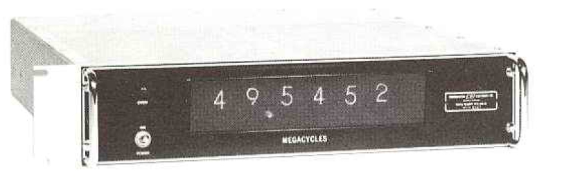
Below is shown a DRO-50 Digital Readout from the 1968 CEI catalog. It contained 6 nixie tubes for the frequency display, and the unit had an accuracy of ±100 Hz. Interestingly, this frequency display was designed specifically for the Hammarlund SP-600 Receivers (R-274A/FRR (Army), R-274B/FRR (Navy)). I never saw a DRO-50 come across our line and suspect it may not have gone beyond the prototype. About that time, the SP-600s were ending their military service, so there wasn’t much of a market for upgrades. It would still be a few years before I owned an SP-600 of my own, but how would I love to have one fitted with a DRO-50.
What I had instead of nixie tubes were variable capacitors or inductors, which changed the tuned frequency through a kluge of pulleys and strings, all these hidden behind a Raymond-Loewy-designed bezel and operated by the tuning knob.
What was visible on the front of the radio was an irregular representation of frequencies covering the tuning range of the radio, in other words, the dial. As you rotated the tuning knob, you set the whole tuning mechanism in motion. Signals were progressively tuned, processed, and reported through the speaker or headset as you advanced higher or lower.
Somehow the frequencies never quite agreed with the numbers or divisions on the dial. It could be that the circuits inside the radio were out of alignment. Just as likely, the design of the dial was determined using a preproduction prototype which could not possibly account for the tolerances of the components used on the assembly line.
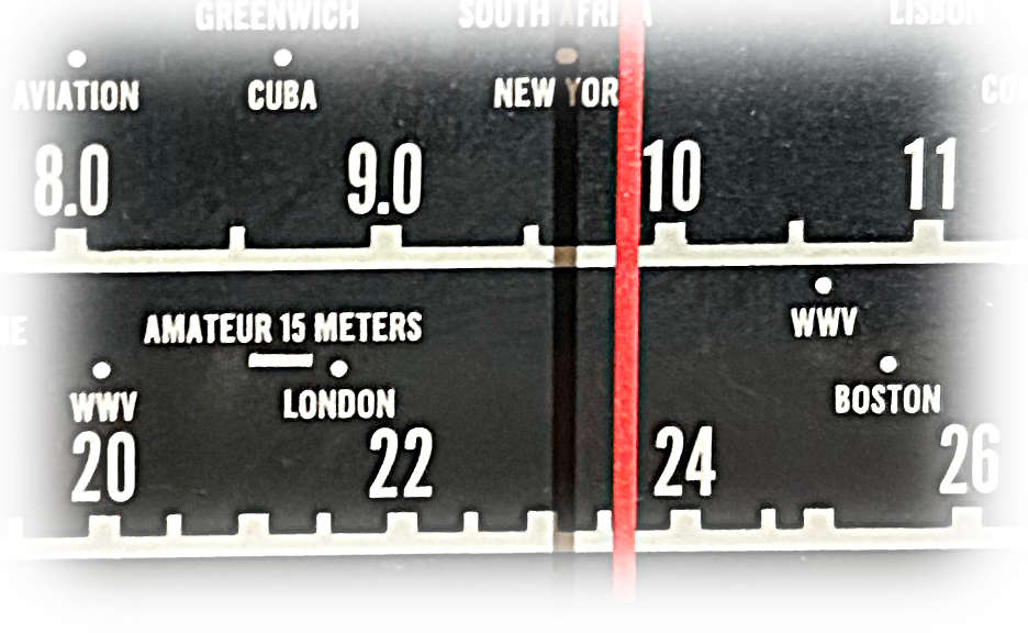
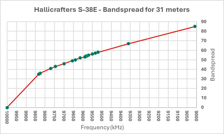
Consider the figure at the beginning of this posting. It is a portion of the dial on a Hallicrafters S-38E – magnified somewhat. The full dial on the E model was big and bright. It extended across the front panel of the radio and presented frequency readout about as well as was possible. Nevertheless, there were real shortcomings.
The figure is not only typical if communication receivers of the time but also living room console radios of an earlier period. Take the 31-meter band as an example. Broadcast stations were bunched roughly between 9400 kHz and 9800 kHz. At 5-kHz channel spacing, this resulted in roughly 80 channels. Of course, not all were in use at any given time, but still a smidgeon turn of the knob could traverse two or three stations.
This situation was relieved somewhat on communication receivers by the addition of a bandspread – a separate tuning mechanism which could effectively magnify a small portion of the main dial. The idea was to place the main tuning dial at the high end of the desired band and the bandspread at 0. Then, by tuning the bandspread toward the other end, lower frequencies could be tuned with greater separation.
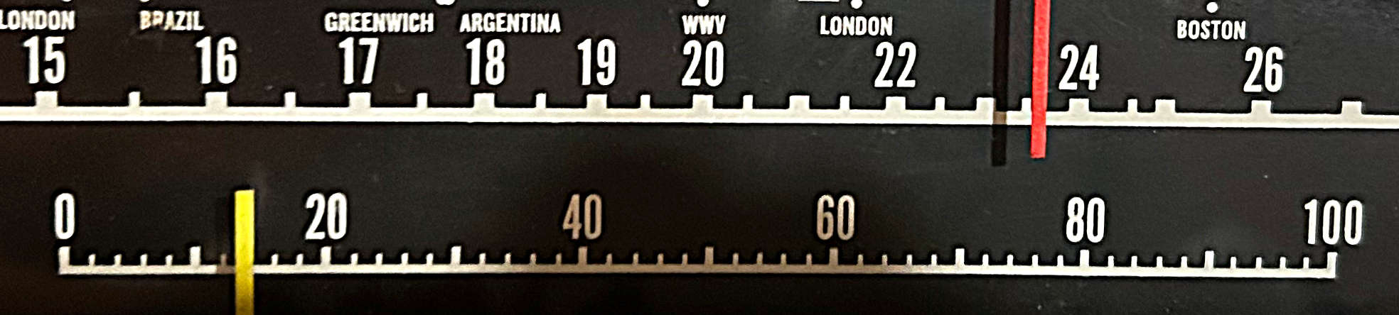
Since the bandspread could be used at any place within the tuning range of the radio, a separate dial became a problem, so it was usually annotated with a simple logging scale incremented linearly from 0 to 100. Thus, one had to compile a log-to-frequency conversion table or graph to interpret the frequency. More sophisticated receivers could display the 80- through 10-meter ham bands on the bandspread dials.
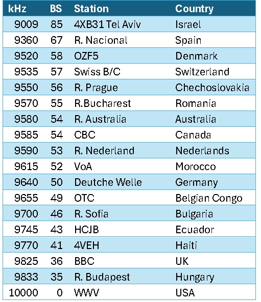
As an example, I located some notes made in 1959 using the S-38E. The table shows the frequency, bandspread reading, station and country. Thirty-one meters was an easy match for the bandspread, as WWV on 10000 kHz was a steady marker which you could use to calibrate the bandspread with the main tuning. For all practical purposes, the band was bounded by the Voice of Spain on 9360 kHz and R. Budapest on 9833 kHz. For many years, Tel Aviv was an outlier on 9009 kHz.
Alternately, one could construct a graph as shown below. Unfortunately, most inexpensive radios did not produce linear tuning, so you couldn’t simply draw a straight line between two points on a graph and expect to interpolate the intermediate frequencies with accuracy. Instead, graphs were constructed laboriously by hand adding intermediate points for known frequencies. The figure shows the resulting parabolic function where the slope is greater on higher frequencies and gradually levels off as the bandspread is tuned lower. Notice that most of the activity was mashed between 40 and 60 on the bandspread, then compare this with the picture of the bandspread above.
 On the S-38E a bandspread was something of an improvement, but not the complete answer. The problem only got worse as you went higher in frequency. At 19 and 16 meters the band compression became quite severe.
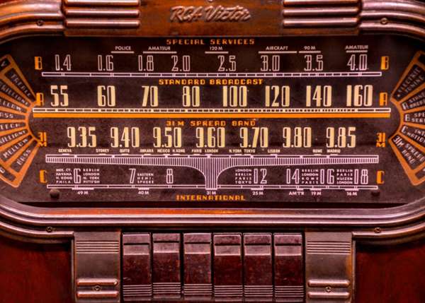
Our esteemed leader, Thomas, occasionally uses a picture of the dial shown below as a lead figure of a posting. It is possibly an RCA Victor Model 110k console radio. When I see this, I think, who wouldn’t give a king’s ransom to own that radio in its fully restored condition? Note the 31-meter band has been magnified as its own separate band and appears in a near linear progression. Thirty-one meters was arguably the center of international shortwave broadcasting in the golden age.
Have you ever wondered what the rest of that radio looks like? Here’s one in sore need of some Pledge. Now imagine yourself, perhaps 11 or 12 years old, perched in front of it on your grandmother’s needlepoint stool tweaking the dial. If you have experienced this, no explanation is necessary. If you haven’t, none is possible.
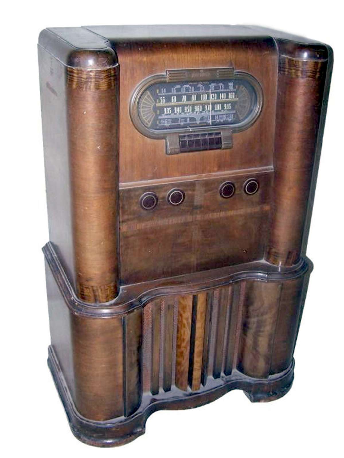
Source: https://www.liveauctioneers.com/
So, as it turns out, I have tempered my earlier conviction that a digital frequency readout is necessarily better than a classic dial. Not to say you can easily pry the PL-880 with 10-Hz resolution from my cold, stiff hands, but I have come to realize that intrigue and mystery of shortwave listening rested in the uncertainty of knowing exactly what frequency you were on. There was always the possibility that the elusive Nibi Nibi Islands lay somewhere near the shadow cast by the dial pointer. It was a land of enchantment, and once you left its borders, you could never return again.
For me, it’s the markings. As with the RCA and the closeup at the top, marking all that stuff is what gets me going. Even my DX-160 has enough things marked on the dial for me to go “oh, cool!”
Gotta be a horizontal slide-rule though – none of those half-circles! 😀
The article was nice but not concise and too long so fell asleep reading so you get a C-.
Great article! I had an S-38E as a kid back in the early 60s and did a lot of SWLing from near Ocean City, MD. Later acquired an NC-105 (rare now), and its manual had the 0 – 100 bandspread fully calibrated in a chart for all the ham and SW bands. It was surprisingly accurate but very non-linear. I used an old Lafayette 100kHz/1MHz battery powered xtal calibrator to help in the calibration. I ultimately graduated to an NC-190 which had both ham and major SW bands on a calibrated bandspread. I got my ham ticket at 16 and ultimately had to sell everything to pay for college a couple of years later. The modern digital receivers are great, but just don’t have the charm and nostalgia of the old slide rule, analog dial receivers.
Frank
W7YAZ (formerly K3YAZ)
“So, as it turns out, I have tempered my earlier conviction that a digital frequency readout is necessarily better than a classic dial. Not to say you can easily pry the PL-880 with 10-Hz resolution from my cold, stiff hands, but I have come to realize that intrigue and mystery of shortwave listening rested in the uncertainty of knowing exactly what frequency you were on. There was always the possibility that the elusive Nibi Nibi Islands lay somewhere near the shadow cast by the dial pointer. It was a land of enchantment, and once you left its borders, you could never return again.”
Yes, Bob, absolutely YES! A land of enchantment indeed.
Well written. I enjoyed it thoroughly.
Cheers, Jock
I really like how the Panasonic RF-2200 solved this problem. You would turn on the 500 Khz crystal calibrator, rotate the dial to a marked point that also had a mechanical detent. Push a lever down, where the scale is then stopped by using the detent, allowing you to rotate the tuning knob until a zero beat was reached. After releasing the lever, the dial was engaged with the tuning knob, and the dial then was synchronized to the correct frequency. The dial could then be calibrated every 500Khz that way. In addition, 125 KHz blips could be turned on to let you know how far off you were when between the 500Khz Cal points.
Great article! I never before knew about the SP-600 being outfitted with a digital readout. And likewise, I never seem to figure out how the bandspread is supposed to work for each different radio. Your explanation helps a lot.
SWL is not dead, it just needs a few more inquisitive people … if only we could drag them away from their cell phones.
Every time I see a photo of a receiver with a slide rule dial I’m filled with a sense of nostalgia. Those dials proudly announced “I’m no ordinary radio, I’m SPECIAL!”. As a young teenager I was certain that the semicircular, green, back-lit main dial of my Hallicrafters S-40A and accompanying bandspread dial represented the pinnacle of frequency readout technology!
I remember recording station frequencies with a three number system: bandswitch position, logging scale position, and bandspread (e.g., 3-6-27). I’ve used that or a similar system on more than one analog radio.
No, I wouldn’t want to give up 10 Hz resolution digital readouts and waterfall displays, but those early dials were really something!
A big love affair with dials and knobs for me… !
A barn yard National HRO5AT receiver came into my possession. I was amazed after nearly
70+ years how well the tuning dial tracked after restoration to the original
scribed tuning curve!
I can forward you a picture view if interested in the results.
Awesome article. Mind if I share it on my YouTube channel, Tom’s Radio Room Show (hamard88)?
Tom Stiles
My pleasure, Tom. Go ahead.