
One of the great things about the SWLing Post is that readers share their varied–and highly creative–methods of playing radio. A few weeks ago, SWLing Post reader, London Shortwave, shared his portable SDR set-up with us; he uses this outdoors to mitigate London’s heavy radio interference. Dennis Walter, president of Germany-based Bonito, commented, and later posted an alternative portable SDR solution using the Bonito RadioJet IF receiver.
Below, London Shortwave shares a guest post (also viewable on his blog) which describes in detail his design for his portable SDR around the FunCube Dongle Pro+ and an 8″ Windows tablet, and explains how effectively it works for him. This post includes recordings and a video; it’s an excellent tutorial:
DESIGNING A PORTABLE SDR SYSTEM
This article is a follow up to the submission I made to the SWLing Post a little while ago. In short, the idea was to combine the FunCube Dongle Pro+ USB-based software defined radio (SDR) with an 8″ Windows tablet running SDR# to have a portable, on-the-go SDR solution.
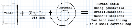
The original inspiration
Tablet radio interference
At the outset, I thought that all that was necessary was a tablet (I chose Toshiba Encore 8″), the FunCube dongle itself and just some antenna wire. This turned out to be a naive assumption because the tablet’s USB interface injected enormous amounts of radio frequency interference (RFI) into the SDR, making listening on some shortwave frequencies essentially impossible. Just to be sure that I wasn’t being plagued by a defect of my chosen tablet model, I tried out the same set-up on a Dell Venue 8, with identical results.
To deal with the issue of tablet-generated RFI, I bought a galvanic USB isolator, which, in essence, is a box that breaks the electrical connection between the USB dongle and the tablet’s USB interface while allowing USB data to pass through in both directions.
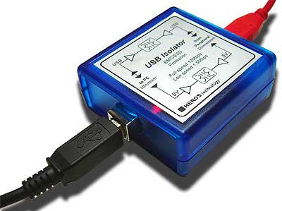
Heros Technology galvanic USB isolator
Additional power for the SDR
Connections
The isolator resolved the RFI issue completely, but created another problem altogether: the device specifications state that the isolator’s power output is restricted to 100mA at 5V. This is sufficient for USB devices that are self-powered but not for the FunCube dongle that draws all of its power from the USB port to which it is connected.
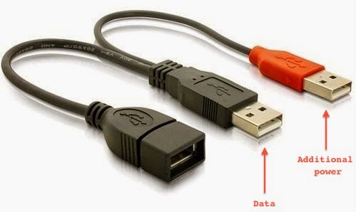
USB Y cable
One way to supply extra power to a USB device is to use a “Y-cable”. Such cables have one extra USB plug that can be attached to a source of additional power (for example, a USB power bank). This solution is commonly used to connect power-hungry items, such as large hard disks, to low-power, portable computing devices (laptops and tablets). Having bought this cable, my next step was to find/improvise a battery that meets the USB power specifications (5V, 500mA).
Yet more interference
My first thought was to use the mobile USB power bank that I use to charge my iPhone while on the go. After all, it already has a USB port and supplies power with the right voltage. Once again, my expectations were confounded and RFI reared its ugly head! The power bank radiates significant interference into the circuit because it uses a switching regulator to maintain steady voltage. Luckily, I came across Gomadic’s portable AA battery pack with regulated 5V output that emits way less interference than any of the other USB batteries I tried (my intermediate solution used 4 rechargeable AA batteries and a makeshift USB connector, and although this resulted in zero additional interference I decided that it’s not safe to supply the SDR with unregulated voltage that doesn’t match the rest of the circuit). I used the handy passthrough USB voltmeter I bought in Maplin to check that Gomadic’s nice-looking gadget does indeed give out 5V as advertised.
So, what can one do with the remaining RFI from the additional power supply? It turns out that it can be mitigated quite effectively by inserting a balun (item 10 on Figure 2) between the SDR and the antenna wire (item 12). The balun is connected to the SDR with a coaxial cable (the “feed line”, item 11). Additionally, ferrite choke rings (item 9) attached to the feed line help reduce this RFI further: winding the feed line through the choke rings several times is sufficient. However, neither the balun nor the chokes are effective enough to replace the USB isolator! It appears they only help with the noise generated by the power supply, which is relatively minor anyway.
Cost vs Portability
When SWLing Post published the details of my intermediate solution, Dennis Walter – one of the engineers behind Bonito RadioJet – popped up in the comments section and suggested that my setup is too tedious, as it involves lots of cables, and that his SDR is superior in terms of portability and the supplied software. While I haven’t had the chance to evaluate RadioJet, I pointed out that the cost of his radio is significantly higher than that of all of my components put together. I also mentioned that the free SDR# software I use is superb: it sounds excellent and offers a number of features that many software packages and conventional radios don’t have. So, having finalised my design, I thought that it might be time to tally up the cost and listen to the results.
Below is the full component list:
1) Toshiba Encore 8″ tablet $194
2) On The Go USB host cable for Toshiba’s micro USB connector: $7
3) Heros Technology USB Isolator: $125
4) USB Y cable with two males + 1 female plugs: $8
5) Gomadic Portable AA Battery Pack with regulated 5V output: $20
6) Gomadic female USB connector tip: $6
8) USB volt-meter (optional): $33
11) Feedline cables $7
12) 6 metres of thick copper antenna wire: $8
Adding up the prices of items 2 – 12 (and excluding the optional voltmeter) brings the total cost to $449 vs. Bonito RadioJet’s $689. For the price difference you can throw in the Toshiba tablet at $194 and still have some change, enough to buy a carrier bag and perhaps even a nice pair of headphones!

Figure 1. Radio components

Figure 2. Antenna components
In terms of portability, the entire setup fits nicely into an 11″ laptop carrier bag.
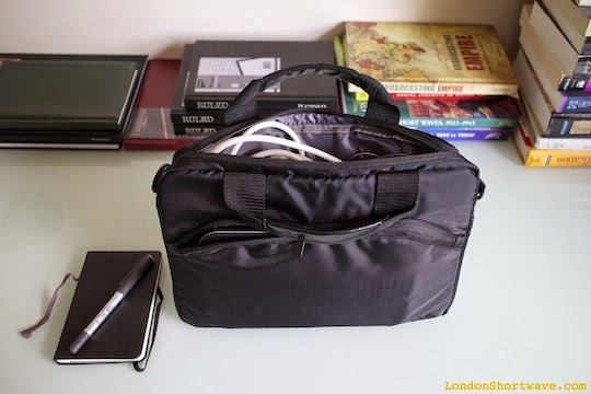
Figure 3. Packing the components into an 11″ carrier bag
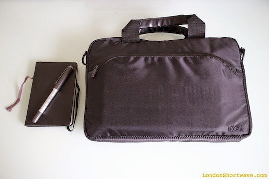
Figure 4. Ready to go
Setting things up in the field is not particularly cumbersome, either:

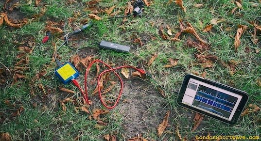
Figure 5. Portable SDR setup in action in a local park
As for the results, listen to the below snippets and be the judge. The only thing I will say is that none of my other portable radios have ever given me this kind of performance, not even with the long wire antenna attached:
And while we’re at it, here’s a demo video:
Portable SDR on Toshiba Encore 8″ Tablet from London Shortwave on Vimeo.
At one point I wanted to build an enclosure to house the FunCube dongle, the power supply and the USB isolator in a single tidy unit, but I no longer see the need. It’s easy to pack all of those items into the carrier bag and also they are all useful individually: the USB isolator can be paired with other SDRs, and I recently discovered a neat additional use for the Gomadic battery pack.
Well, that brings me to the end of this post. I hope my design will inspire you to come up with your own portable SDR system, and that you will share your results with me in the comments section. Happy listening!

Thank your for your wonderful work!
I have a question about the RFI switching noise. What frequencies did you find unusable?
Also were their difference in the two tablets or were the chipsets common enought to be the same range?
You could add bypass capacitors either directly to the USB cable (a couple of uF and pF caps across Vcc to gnd in parallel) or if you wanted to get fancy you could build a pcb with caps and usb connectors and that would take care of the switching noise.
Hi London Shortwave,
thanks for the Article, I need to read and understand it correctly. It is cool to see the reactions of tThese articles. One important Thing: The RadioJet 1102S actually costs only 529 USD and not 689,-USD and please don’t forget: The 1102S is defintely the MUCH better Receiver. I am happy to meet you in Newark end of September.
Dennis
Hi Dennis,
Great news regarding the price reduction of your radio unit! RadioJet might well be the much better receiver out of the two but so far I can’t judge that for myself, and nor can the readers 😉 One way you could demonstrate this is by posting some recordings of, say, the same station signals that I included in the above article (we’re heading into autumn now so propagation is likely to improve). At the end of the day, the only thing that matters is what we can hear with our own ears! It’s also worth remembering that any SDR will need a decent antenna and additional measures to prevent RFI from the tablet leaking into the radio, so these must also be included in the final cost.
73s!
Yes, of course. I made Videos in Part two which needs to be translated.
I really must say, that I am very pleased about your articles. Because I think, that I never tried it on a tablet, if I didn’t read your articels. Thank you very much. I hope you bring your System with you to Newark and than you can try it by your self, inside of the Hall.
CU in Newark and keep listening
Dennis
I stand by my July 16th comment: Forget the USB isolator. Use a reasonable
antenna with a counterpose and a common-mode yoke instead. I had comparable
problems at my SW mobile station. The single most important measure was
quite that.
The 1:9 balun eases the problem a bit but does not solve it: Antenna is
everywhere where unsymmetric currents are floating around. Eliminate them at
the receiver input and your problems are mostly solved. The balun has two
input terminals for a reason.
Terminate your receiver input with a 50 Ohms dummy load. Remove the USB
isolator. If that mutes your RX you know that I am right.
vy 73
Alexander
DL4NO
@Alexander, thanks, do you mind sharing a picture of what such a choking/counterpose combo should look like?
The chokes I have in place around the FunCube dongle (item 9 in Figure 2) deal very well with the noise generated by the portable power supply, and do exactly what you say, but can’t at all handle the interference that the tablet is bleeding from the USB end. Also, I haven’t dealt with grounding/counterposing because that would mean packing fairly large items into the bag (ground rod, more wire) and I wanted this set-up to be as portable as possible.
Cheers!
@Dave: Please see the pictures at http://www.dl4no.de/thema/mobilbe0.htm first. This page of my ham radio Web site deals with mag mounts and their interference suppression. My old car had quite some electric noise on the inside. I started with S7 to S9 noise from my own car.
The first picture deals with the capacity between the mag mount body and the car body. I measured some 300 pF which is about 50 Ohms at 14 MHz. The base of the antenna is quite “hot” this way. The diagram shows the resonance of my 20m antenna on a fixed and on the mag mount without any readjustment. BTW: I worked DL – VK2 with this mag mount while driving 120 km/h. The OM on the other side had a 3-element yagi.
Without the yoke seen in the last picture the cable acted like the second branch of a dipole despite or exactly because of the yoke on the other end. The yoke alone brought the interference down to S3 on 20m. A few more measures at the station wiring inside the car brought the interference below the ambient noise. Those measures are not important for your setup.
Back to your problem: If I interpret your pictures correctly you only connect two cables to your 1:9 balun: A coax cable and your “antenna”, a single wire. The other input terminal of your balun is open. This way your balun does not act like a balun, but like a capacitor between the windings. The manufacturer says: “The feeder winding is isolated from the antenna to reduce mains borne noise and antenna/feeder interaction.”
So simply cut your antenna wire in half and connect one half each to the input terminals of your balun. Then connect the balun to your SDR as before. Perhaps you should move the “iron” on the black coax cable to the SMA connector at your Funcube dongle.
Thank you for this, will investigate it thoroughly and report on any improvements 🙂