
Many thanks to SWLing Post contributor, Steven Crawford, who writes:
As the 7600GR supplies 6v DC to the external antenna jack to power their active loop antennas there seems to be a great deal of confusion on the web about whether one can or cannot use an external antenna such as a random length of wire attached to the center tip of a barrel connector.
I have been unable to locate the blog entry but I seem to remember you discussing this in one of your posts. In it you mentioned you had built a widget that killed the voltage and allowed you to use the external antenna of your choice. I would appreciate your thoughts on a random wire to center tip antenna and details of the widget you built when you have time.
 Thank you for your question, Steven. I hope a reader can help point to the post you’ve mentioned. I believe I recall reading this in a guest post–I know I’ve never used a device to kill the 6V phantom load in the antenna out jack.
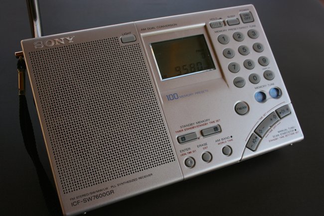
I suppose I’ve (incorrectly?) assumed the Sony would only push voltage out if connected to the Sony AN-LP1 (see right).
I know I’ve used a number of antennas with the ICF-SW7600GR: long wires, the PK Loop, The EF-SWL, the NASA PA 30, and even a rather large multi-band dipole when I recorded the final broadcast of RNW. I’ve never experienced a problem, nor damaged the antenna/receiver as of yet.
Can anyone shed some light on this? Please comment!
Hi, this thread has been dormant for 5 years I notice, but for a newcomer like me still relevant. With the BBC starting broadcasting on SW again, I thought it might be nice to pick-up SW listening again. As I found out since the 70-ties when we used to listen to the Dutch News on SW when on holidays, a lot has changed since then. Not for the better unfortunately.
Anyway, I picked up a now very affordable Sony ICF-7600DS which I now want to hook-up to a random length end fed wire antenna. The idea is to have a 9:1 UNUN outside, enter the home with a 50 Ohm coax, but then how to connect to the Sony? I pulled out the schematics (https://elektrotanya.com/sony_icf-7600ds_schematic.pdf/download.html) and noticed that this model does not yet output the 6V for an active antenna as discussed in this tread.
My question is however: what is the impedance of the external antenna connector? I know that part of this circuit has been changed over the years and my limited knowledge suggests that the change of R168 from 33 Ohm to 220 Ohm in the later model may also have impacted the impedance. Am I correct to assume that the impedance of this Sony is not 50 but rather somewhere near 300 ohm?
And if that is the case, would inserting a 1:4 balun between the coax and the input jack be the way to go to match impedance? I would be going from 50 ohm unbalanced to about 200 ohm balanced, putting one end of the unbalance part to ground, but I assume that this would still be a better match than a 50 ohm coax?
Keen to get feedback, as you can tell I am not (yet) an expert, but happy to learn!
I asked on a reddit post long ago and someone went over the shematic of it for me and apparently there is a little capacitor or something like that inline that would stop the low level voltage even if the 2 parts, inner and outer conductor of coax or dipole touched as well as protecting from static discharge a little. So it’s completely fine the only issue is since it’s made to be used with Sonys preamped active antenna it’s not very sensitive. Really unfortunate. I wanted to be able to use my computer and stuff at the same time and direct connecting like that to an outdoor antenna isolates the radio really well even when I use a crappy switch mode wall wart. Major flaw in an otherwise perfect radio. Guess I’ll just get one of those de1103 radios just for fun.
Looking at the schematic, the built-in whip antenna and the external antenna jack both go to the same r.f. amplifier
Since this is a Sony SW7600GR antenna question I thought I’d add another. I love the receiver but have trouble with LW and MW using any external antenna. I’ve noticed that when you cross the threshold between 1711 to 1710 khz the external antenna seems to be ignored and 1710 khz down to 150 khz only uses the internal ferrite antenna. I’m not sure what happens with an external in that frequency range on the Sony – but, all an external seems to do in that range is null out the signal and add MW overloading down in the LW frequencies. If I unplug the external and go outside to reduce the noise I can hear beacons in LW using just the internal ferrite. Seems other portable shortwaves don’t have this issue with random wires from what I’ve seen on YouTube. Anyone have some thoughts on this? Am I stuck with using the ferrite with a passive loop to improve the Sony on LW and MW?
Looking at the schematic diagram, LW and MW use only the internal ferrite antenna.
Thanks, Jamie! That’s too bad – I have a great longwire endfed antenna and it does nothing for my Sony 🙁 – ah well!
Es una pena pero es asi lamentablemente. He tenido éxito en mejorar el resultado pero con una loop por inductancia. Saludos Gabriel CX7BI – CX0001
Hi,
Yes, it does push voltage out if you use any external with a plug. I was also initially concerned with the same question (and also if it affected the antenna impedance) for the SW76000GR and purchased a blocking capacitor adapter (https://www.amazon.com/gp/product/B0006PIR8G/) between the ext jack and the antenna and found that it made absolutely no difference with dipoles, random wires, etc. (don’t have a loop). I did measure the voltage with the blocking cap in and yes it did block. But, you shouldn’t have any issue.
Thank you Thomas for posting my inquiry and thanks to all who replied. Guy Atkins reminded me to dig deeper as I was familiar with Stephan Grosklas’ site, I simply had not dug any deeper than the 7600GR entry. Thanks again to all!
Steve
Off topic. I wish someone could tell me how to stop the alarm from going off each day. I have read the instructions but they make no sense to me. Thanks.
As I understand it there are two ways. One temporary and one permanent:
Temporary — Turn the radio off. Slide the Lock button to the right. A key will show in the display when the Lock button is in the correct position. This will stop the alarm as long as the radio is turned off and locked
Permanent — If STANDBY A is showing in the display. Turn the radio off, leave the HOLD with off, no key showing in the display. With the radio off press and hold down the STANDBY MEMORY button A until STANDBY A disappears from the display. Release the button and do a quick press and release of the same button. When STANDBY A disappears you have 1 second to do the release, press, release. If STANDBY B is showing in the display. Turn the radio off, leave the HOLD with off, no key showing in the display. With the radio off press and hold down the STANDBY MEMORY button B until STANDBY B disappears from the display. Release the button and do a quick press and release of the same button. When STANDBY B disappears you have 1 second to do the release, press, release.
Repeat until neither STANDBY A or STANDBY B show up in the LCD display.
Somebody correct me if I’m wrong.
I have one of these and I like it a lot, but I dropped it and it landed on the BFO control. I’d like to replace the pot. Does anyone have the schematic or parts list? It would be helpful to know the value of the pot and if there is a suggested replacement part.
I think Steven might be thinking of Stephan Grosklas’ excellent web site on the entire Sony ICF-SW7600 series (http://stephan.win31.de/sony7600.htm). There is a section under the SW7600GR portion which discusses the voltage riding on the antenna input. Defeating this small voltage is not really necessary, as this information describes:
—————
About the antenna circuit and external antennas
The following information is from an older posting, :
The ext. antenna socket is “hot”, i.e. powered through a 470 ohm resistence + 100 uH coil. This means that it will deliver approx. 10 mA DC current to the external antenna circuit. The coil is to prevent “polluting” the power circuit of the radio with radio frequency signal. Evidently, the purpose of this arrangement is to “inform” the accessory antenna when the radio is turned on. In case of the Sony AN-LP1 it turns on the antenna without need to use the antenna power switch. However, the 7600G will NOT power the antenna, the 10 mA are not enough to power the amplifier circuit. The power for the AN-LP1 comes from its own batteries. You can use this feature with any active antenna by including a proper power-up circuit – a nice feature if your active antenna is located far away from the radio and you want it to turn on and off automatically when you use your radio.
You can connect any other antenna (provided it is correctly designed and installed) to the EXT ANT socket without risking to damage the radio. However, if the external antenna circuit has low DC resistence, it will drain some current from the radio. Therefore, you will experiment slightly higher power consumption from your batteries (up to 10% at normal listening volume). You can avoid this current drain by including a small ceramic capacitor (1000 pF) in series with the antenna circuit, however I don’t think it is really necessary.
The 7600G has some basic protection build into the EXT ANT input circuit. Any static buid-up will be drained off via the power circuit mentioned in point 1. It also includes a diode pair (1SS123) to protect the input RF amplifier FET from damage due to too strong signals or an accidental connection of the antenna to a low voltage AC source. IT IS NOT A SUBSTITUTE FOR A PROPER ANTENNA GROUNDING AND LIGHTNING PROTECTION IF YOU USE AN EXTERNAL ANTENNA – YOU STILL NEED TO PROPERLY GROUND YOUR EXTERNAL ANTENNA AND PROTECT YOUR RADIO, but it builds some margin of safety to protect the front-end FET – a common problem with the Sony 2001D (2010).
——————
Hi Thomas,
I can’t see any reason you can’t connect a longwire to the central post and plug it into the antenna jack of the receiver. Just ensure that you don’t short out the plug when soldering the wire as that may short the radio batteries and drain them rapidly. Having a small DC potential on the antenna won’t affect the antennas performance.
Hope this helps.
Cheers…….. Phil vk2gjf
Hi, a good antenna but very expensive in comparison to the materials of manufacture that are of the most basic a lot of plastic and little electronic, by the way, it is almost worth more the antenna than the radio.
Best price loop antenna (Degen 31MS) MW, SW