
Many thanks to SWLing Post contributor, Eric McFadden (WD8RIF), who shares the following announcement from Ken (WA4MNT) via the QRP-L forum:
QRPGuys is open for orders after this year’s Summer shutdown. We have added a product that may be of special interest to SWL listeners and some hams. It is an active antenna splitter that will enable connection to three receivers from a single antenna.
Product Deescription:
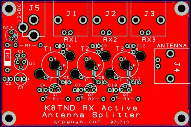
The KN8TND Active RX Antenna Splitter will allow you to use one antenna with mulitple HF receivers simultaneously. Many hams and SWLers like to monitor several bands and/or frequencies, i.e. 14.300, international nautical emergency freq, 14.100, world HF beacons, etc, etc. Having two or three HF receiving antennas is a luxury some Hams and SWLers can’t afford. With the active receiver antenna splitter you can use one antenna and three receivers at the same time. Keep abreast of what’s going on on the bands, put some of those dust collecting receivers back in action. On a difficulty scale of 1 to 5, this kit is a 2. Build time is about 2 hours, depending on your experience, with the normal kit tools. Bear in mind, this is for receiving only. For HF transceivers you would need a T/R switch to your tuned transmitting antenna.
Come by and see it at:
https://qrpguys.com/k8tnd-active-antenna-splitter
QRPGuys makes amazing QRP kits. Immediately after receiving Eric’s email, I purchased the active antenna splitter kit. Total cost with shipping was $25 US. A true bargain! Although I already have an ELAD Active antenna splitter, this one would be nice to take to the field as it’s much smaller and lighter weight.
Click here to check out the new Active Antenna Splitter at QRPGuys.
This looks like a nice kit for the money! I would like to see QRPGuys give a few more points of information:
-Current draw @12VDC? (Should be quite low)
-Does the active circuit provide unity gain (zero)?
-Typical port-to-port separation in dB
-Is the range of the splitter from LW through HF without any significant attenuation?
-Is there a brand-name project box such as from Hammond that he board will fit?
Perhaps this is being too picky for such a value-priced kit, but I think these are the kind of questions some other builders would ask before buying.
Some quick guesstimates, based on looking but no deep analysis:
Current draw? Ballpark ~35mA. LED seems to be running at ~15mA, each amp seems to be biassed to around 5mA, plus another 3mA or so regulator quiescent current.
Gain looks near to unity,
Port separation is going to be dependant on construction – the layout doesn’t look anywhere near optimal but, realistically, it’s not really a major issue for Rx.
Bandwidth? Their statement of “AM to 50MHz” looks about right; my rough eyeball-guess suggests 500~1000kHz up to nearly 100MHz, but the transformers are likely to limit the top end.
As for gain, willing some gain one may consider adding a wideband LNA between the antenna and the splitter; while I don’t really like the idea too much, since I believe that an rx antenna preamp should be AT the antenna, I recognize that it may still be useful in some cases, and given the small size of the splitter and if an LNA board, the two may both fit inside a small enclosure and there will probably be enough room to add a switch to bypass the LNA
Forgot, another use of a splitter like that would be comparing the performance of different receivers, for example one may connect a reference rx at one ofe the splitter outputs and the test rx to another and be able to check, in real time, how they perform with the same antenna (signal and band conditions)
The only note I may make, after looking at the circuit is that the choice of 12V for the splitter power supply is, in my humble opinion, a bad one; adapting the circuit to run on 5V would have allowed to power the splitter using USB power so SDR user wouldn’t need a separate power supply for the splitter and using it for mobile operation would be easier, other than that, not having tried it (waiting for a field review :D) I can only say that, judging from the circuit, it should work quite well, although I’m not totally sure about the noise it may introduce
It’s a (string of) simple single-transistor common base amps, and fed from a 9v regulator anyway. It’d probably work quite well at 5v or below with only minor changes (e.g. drop the emitter resistors to 1.2k or so, and maybe fiddle the associated caps), though I haven’t deeply analysed that – for example, it’d depend somewhat on the output transformer characteristics, which I haven’t thought about.
Then there’s the little matter of USB power – it’s noisy and unstable, and one of the problems with common-base amps is they have little/no inherent supply rail noise immunity. It’d require a fair bit of filtering and probably a LDO to make it useable in that config which, ballpark, would bring the usable supply down to ~4V.
There’s also room for improvement with the choice of transistors, and definitely some that’d be better choices at 4~6V. 2N3904’s are still pretty good in general, however RF transistors have come a long way in the last 50 or 60 years. But most of the better ones I can think of are SMD, and the typical ham/swl seems to have an aversion to such newfangled parts…
My reference to USB was to USB (cable) powering, that is, using the same source used for an SDR, which may be a battery pack as well, the idea being to have uniform voltage so using the splitter for mobile operations would be easier
As for the transistors, they may be ok, although it would be interesting to measure the noise levels with and without the splitter
For rtx operations, it could be possible to enclose the splitter and a ptt controlled relay into a box, allowing to use the unit for QRP