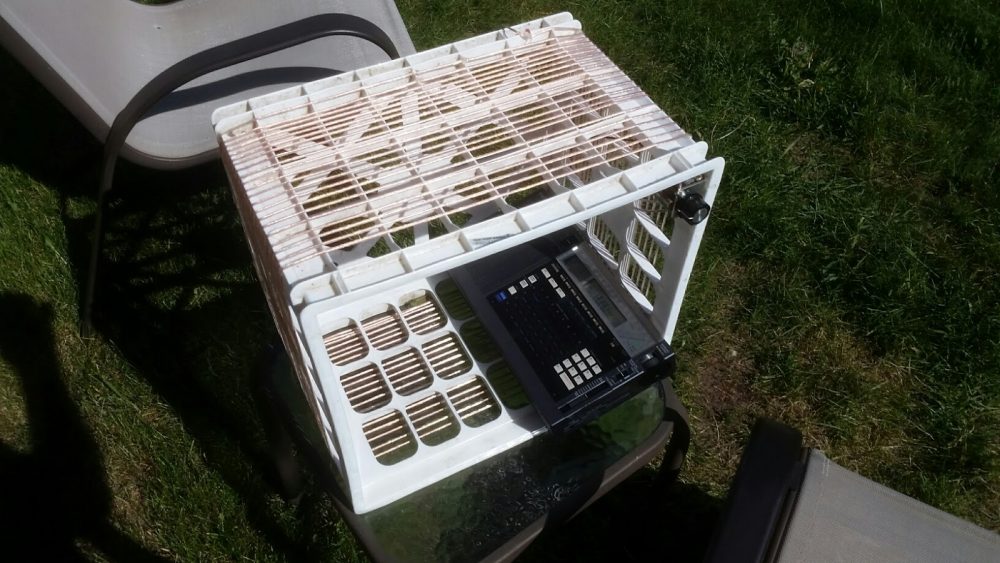
Many thanks to SWLing Post contributor, Andy, who asks the following question in response to a previous post about building a Milk Crate AM Broadcast Loop Antenna:
All references to tuned loop antennas talk about no real connection to the AM radio, but merely inductive coupling.
However, I made a very elementary crystal radio which has no ferrite core or antenna.
I want this loop to be my primary (only) antenna, so I need to feed it directly to my tuning circuit. So I don’t know if I should take a wire from any particular part of the loop, with another wire to ground… and if these 2 wires should be in parallel or series with the tuning elements of the loop antenna.
Thanks!
Good question, Andy! Hopefully someone in the SWLing Post community can comment with some guidance!


It is quite easy to do, actually. I presume that you have high impedance ear phones or headset. It is easiest to set up using those little connector wires that have alligator clips on each end. Use these to connect the rotor as well as the stator of your variable capacitor to each of the leads on your head set. Interpose an appropriate diode (IN34a) between either the stator or the rotor and one of the leads of your head set. So three alligator clip patch cords, a high impedance head set, and IN34a diode is all you need and you are in business. I use mine to listen to all seven of the local AM stations here in Columbus, OH. I have a vernier dial attached to the variable capacitor; between using that for fine tuning and the ability to rotate the loop I can null out any of the seven stations and will hope for some dx, especially if I attach a long wire antenna and use the loop as an antenna tuner…
Try replacing the coil of your crystal set with the loop antenna itself. It will serve two purposes, the first being the L of the L-C tuned circuit, and the second will be its function as the antenna. You may have to add or subtract turns to get it to tune the frequencies of interest. You could also vary the value of your tuning capacitor by using several of its sections in parallel.
Hello
I have made antenna very similar to the photo on 2011-12
https://sites.google.com/site/zliangas/baseketena
That was based on similar design of a ham friend
Useful and 10+ db higher gain then the typical AN200
You should check out Dave Schmarder’s Make-A-Radio Website:
http://makearadio.com/index.php
Especially take a look at the Crystal Radio section – 78 variations.
One of which will fit your need.
73
Bill
WD9EQD
Smithville, NJ
I would like to build one of these to use with my ICF-S5W. Is 20 turns optimal for 530-1700khz?
Zack N8FNR
If you will use a basket for vegetables yes!
https://sites.google.com/site/zliangas/baseketena
it all depends on the inductance (L) of the loop antenna, which tells you how much capacitance (C) you need, according to the resonance equation f^2 = 1/(4*pi*L*C). the bigger the loop and the more turns, the more L it has and the less C you need. with a typical variable capacitor of 350 pF you would need a loop with 270 uH to get down to 530 kHz.
keep in mind these two things:
1. when the turns are very close together or adjacent, they have inherent capacitance so you need less capacitance, and the loop’s maximum frequency is brought down.
2. too many turns can reduce or eliminate reception due to inductive choking.
Actually, the pi should be squared so that the equation becomes equivalent to the one show in this page:
https://en.wikipedia.org/wiki/LC_circuit#Resonance_effect
yes, that’s right. transcription error.
Here is the way I made my dad’s loop antenna into a crystal set.
http://makearadio.com/loops/loops3.php
Having a larger loop will result in better reception.