
 Many thanks to SWLing Post contributor, Frans Goddijn, who writes:
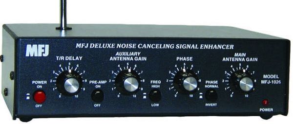
“Last week I purchased the MFJ-1026 ‘noise canceling signal enhancer’ and I posted two blogs with video about it. Initially the device seemed as useless as it is good looking but then I found a configuration where the device is not only pleasant to have but also useful for radio listening.”
Here are Frans’ reports which he kindly shares from these two posts originally published on his blog, Kostverlorenvaart:
Part 1: MFJ-1026 deluxe noise canceling signal enhancer
Using a GRAHN antenna, (a VENHORST wire antenna for noise reference), the iCOM R8600 radio and optional bhi DSP audio noise canceling, trying to see what’s the best way to cancel noise — on the antenna entry point of the radio or at the speaker output end.
In this case the MFJ-1026 seems ineffective. The DSP at the audio output end works well and easy.
I have also tried two GRAHN antennas on the MFJ-1026, one for MAIN and one for AUX but that was also not noticeably effective yet.
I will also try the little whip antenna that MFJ supplied with the box. Further tweaking may turn out to be helpful on some other frequencies / signals.
Before installing the MFJ i used the little TECSUN H-501x to scan the room for any devices producing radio noise. It turned out that the two Apple Homepods sit in a dense cloud of radio noise, the Macbook Pro also radiates noise, EVE smart plugs controlling lights also produce radio noise, two little label printers s well and the HP printer/scanner too. So I moved those to the other end of the toom or to another room.
So far the MFJ-1026 does not do any harm and it looks good on the desk so as a box with buttons it is very pleasing in itself.
Glue Drool
The MFJ-1026 arrived with some odd tiny ‘spider hair’ inside over part of the circuit board. I checked with the dealer and they explained it’s web threads left there by the glue gun that was used to fixate some parts on the board.
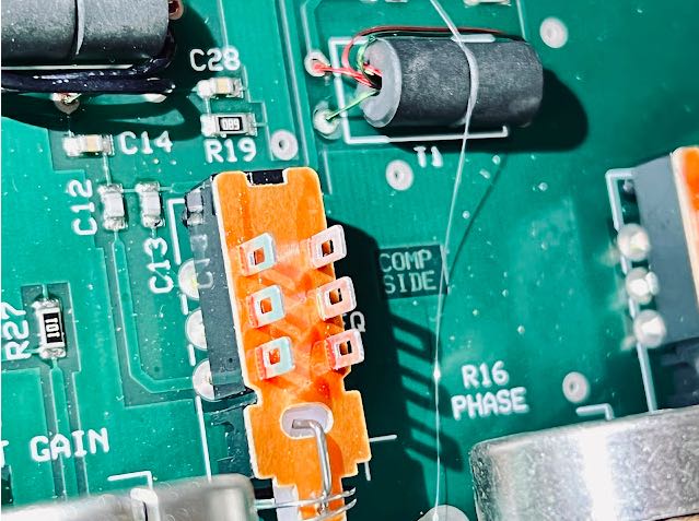
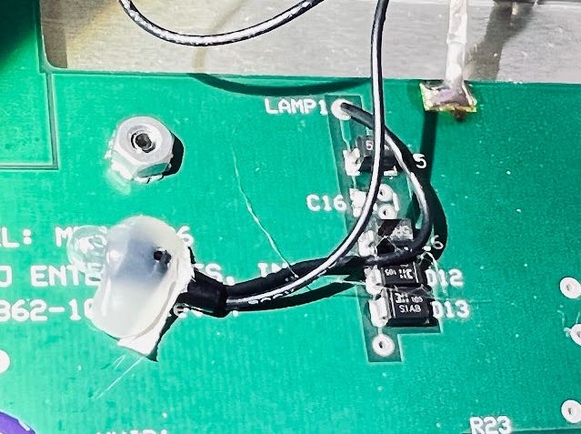
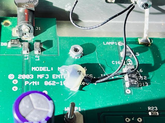
Cleaned up
Part 2: MFJ-1026 can actually work
It can be a challenge to find antenna configurations where the MFJ-1026 actually improves the radio listening experience. The first few days of trying the device seemed transparent and switching it ON or OFF did not make any difference to the radio. Neither did any of the settings of the front panel dials change the signal at all. I tried a wire antenna as MAIN and the MFJ whip as AUX, the wire as AUX and one of the GRAHN loop antennas as MAIN, both GRAHN’s next to each other on the desk, a GRAHN away from the radio and the whip as AUX. None of that nor any dial combo made a difference and it seemed the MFJ-1026 was transparent / indifferent.
Now I found one configuration that works on a frequency that I tried.
Both GRAHN antennas are somewhat distant from the radio. One is on MAIN and one on AUX of the MFJ-1026. While alternatively dialing MAIN and AUX to the max exclusively, I tweaked the direction and toggle options of the GRAHN antennas to each their optimal signal. Next I used them both and used their dials on the MFJ-106 to have them deliver an equally strong signal. Next I turned the PHASE dial and it turned out the most clockwise position had least noise.
Next, switching the MFJ-1026 to the OFF position (this feeds the MAIN antenna direct to the iCOM IC-R8600 radio) delivered a noisy signal as can be heard after a second or two. Switching the MFJ-1026 back ON considerably improved the signal as can be heard after a second or two.
Still, the most significant ‘cleanup’ of sound is done by activating the little bhi DSP device 😉
Best regards,
Frans Goddijn
Amsterdam
The Netherlands
Thank you for sharing your experience with the MFJ-1026, Frans!
I recall John Fallows (VE6EY) speaking about how to optimize noise-cancelling devices when he was a guest on the Ham Radio Workbench podcast; click here for more info. The topic was on diversity reception, but if I remember correctly he also spoke about noise-cancelling devices like the MFJ-1026 as well.
Readers: Check out more of Frans’ radio work at his blog Kostverlorenvaart.
If you have an MFJ-1026 or similar device, please share your experience using it in the comments! Click here to check out the MFJ-1026 at MFJ Enterprises.
It sounds like you were using two similar antennas on the device. I get best results when the aux antenna receives the QRM signal well, but the target signal poorly or not at all. This is what lets you efficiently phase out the offending signal.
I would really like to see some detailed and knowledgeable instructions (or video) on how to use these devices. So many youtube videos on the subject – and most are of hams randomly twisting knobs, and quickly declaring the device either a miracle or trash.
You are correct in that it’s mostly a superficial quicky and declaring miracle or fail randomly.
The device fascinates me how it seems slippery transparent at times, and then again in the same setup on another frequency it demonstrably works wonders.
I also tried dissimilar antennas, sometimes that does gge trick. Then again, in the manual the manufacturer states that similar antennas are advised.
The other day I bought a second hand big magnetic loop that someone home built and especially at low frequencies that one worked well with one of the Grahn loop antennas on AUX.
it’s almost like fishing maybe (i have no experience with it, just from reading) that some days it’s great, some gear feels superb and some of it eludes logic ??
Patience, perseverance, and the simple meditative joy of playing with the devices works well for me.
From the manual:
The MFJ-1026 allows almost any combination of antennas to be used as a system, but the MFJ-1026 works best when the main and noise antennas have the same basic patterns when nulling or peaking distance noise or signals. That means the antennas should be oriented in the same direction and also have the same basic polarization for best performance.
It is not necessary to use any special length of feedline with the antennas, or for the antennas to be “resonant” or physically large. Lower Q and smaller antennas often produce the most stable and reliable performance. Failure to follow this basic guideline will often decrease performance when nulling or peaking distant signals.
[…]
When adding desired signals, the noise and main antennas must both “hear” the desired signal. It is preferable that both antennas be reasonably close together (within a wavelength) and of similar polarization.
[…]
Adding desired signals from a “noisy antenna” into a “quiet antenna’s” signal will only make things worse. In the case where one antenna is significantly noisier than the other, use the quiet antenna for the signal and cancel any noise with the “noisy antenna”.
If the desired application is the removal of distant interference, close spacing is desirable. Close spacing produces a wider and more stable null. Spacings of one half wavelength or less are most desirable when nulling distant interference or peaking distant signals.
If the primary problem is removal of local noise, it is preferable the noise (AUXILIARY) antenna “hear” the noise much louder than it hears desired signals. The noise antenna should be located as close to the noise source as possible, so the noise antenna picks up the least amount of desired signal and largest amount of noise possible. In this case the polarization is unimportant, and the spacing between antennas can be any convenient distance.
[…]
The noise antenna can be a special antenna, or simply a spare antenna not in use at the moment. When nulling local noise, the best antenna would be one located close to the noise source that “hears” the noise much better than any desired signals.
[…]
In order to null or peak a signal, both the MAIN antenna and the AUXILIARY antenna must “hear” the same signal. If the same noise or signal is not present on both antennas, noise or signals can not be properly nulled or peaked. This requirement may require installation of a special antenna near the noise source to null unwanted local noise signals, or require installing a separate low noise receiving antenna to enhance desired distant signals.
[…]
Operation
This unit requires 10 to 15 volts dc, available from your station supply or an optional MFJ-1312B power supply.
If you have a general coverage receiver, select a strong steady signal between 1.5 and 30 MHz. The ideal signal would be ground wave, although the time and frequency standards on 5 , 7.335, and 10 MHz are good alternatives. It is important to select a signal with little or no fading for initial practice.
1. Connect the MFJ-1026 to your station and a suitable power source. See the Installation instructions on page 8.
2. From left to right:
a. Turn the T/R DELAY control fully clockwise.
b. Press and release the POWER switch to place it in the OFF (out) position.
c. Turn the AUXILIARY ANTENNA GAIN control fully counter-clockwise.
d. Release the frequency range for operation below 7-12 MHz, or press and lock it for operation
above 7-12 MHz. In the range of 7-12 MHz, either setting may work.
e. Adjust the MAIN ANTENNA GAIN control fully clockwise.
3. Tune in a strong steady signal.
4. Turn the MFJ-1026 power switch on. The red LED should light and you should hear the internal relay click.
5. You should still hear the same signal. Look at the receiver’s S meter and remember the signal strength. Adjust the MAIN ANTENNA GAIN control counter-clockwise, signal strength should decrease. Turn the control fully counter-clockwise.
6. Advance the AUXILIARY ANTENNA GAIN control clockwise. You should hear signals from the AUXILIARY antenna.
7. Adjust the AUXILIARY ANTENNA GAIN until the signal is just exactly the same as the level observed on the MAIN antenna, or as high as possible.
8. Advance the MAIN ANTENNA GAIN until you just see the S meter change.
9. Adjust the PHASE control for minimum signal. If the signal strength increases or won’t null, change the position of the PHASE switch.
10. Go back and forth between the PHASE and the GAIN control that isn’t totally against the stop while watching for a null. Adjust only one GAIN control, do not adjust the control that is fully advanced. This step may take some practice until you get a “feel” for how the controls work..
11. Practice nulling several steady signals until you are comfortable with the action of the controls.
12
MFJ-1026 Instruction Manual Deluxe Noise Canceling Signal Enhancer
12. Try peaking a signal. The strongest peak will usually be very near the setting of the PHASE control that produces the deepest null for the same signal, but the PHASE switch will be in the opposite position from the null position. When peaking a signal, never adjust gain setting. Adjust the PHASE control and PHASE switch only.
13. After gaining experience on strong steady signals, practice nulling background noise or unwanted signals.
Remember, you can only null a signal or noise if it is present on both the noise and main antennas.
Fading may make it difficult to obtaining a complete null on skywave signals. The most consistent null will occur if the antennas are moderately close together (between 1/2 and 1/8 wl apart), oriented in the same direction, and sharing the same polarization.
[…]
Other Applications
Since this unit is really an adjustable phasing network that combines two antennas to give various directional patterns, it can improve receiving signal levels even in the absence of strong noise. For example:
1. Two parallel Beverage antennas spaced an eighth to quarter wave apart with an eighth to quarter wave stagger in the desired direction can be combined to improve front to back, steer nulls, or add desired signals.
2. Two verticals or dipoles can be combined producing a steerable array capable of peaking or nulling signals.
3. A Beverage and a quiet main transmitting antenna can be combined to enhance weak signals.
Many other combinations are possible. The best system is found by experimentation.
[…]
Dear Frans,
Thank you for your detailed post. I must have missed it in the manual where it stated that the 1026 had a max frequency of 12 MHz. It is all now clear as I have been trying to clear up 12 db plus noise on the 10 metre band and a little lower on the 6 metre band. The noise source was isolated to my back door neighbour’s air conditioning unit, even when it was not running and on standby.
I was successful in removing 3 S-points of noise, though nowhere near enough for effective copies of signals and monitoring call frequencies at 28.490 MHz here in Victoria, Australia.
I just checked the manual, and it states that the device works up to 30 MHz. I suppose it does, though not to my desires at my QTH. I disconnected it yesterday and was thinking of putting it up for sale. Maybe I will hang onto it for a while longer.
Warm regards,
Paul.
Dalyston, Victoria,
AUSTRALIA
Settings might be surprising. It is not always the lowest noise depending on the type and source of the noise. I found it is best to look for the highest signal-to-noise ratio to get the most intelligible signal. This is best seen on an SDR waterfall that can show Peak signal, Noise Floor, and S/N ratio like SDR# does. I currently use TWO phasers with three antennas to get somewhat usable results in the noisy condo! And once in a while, the phasers are not better than just the native antenna by itself.
Remarkable! Three antennas and two phasers ?
I feel i want to try that too sometime.
My experience with these phasing units is that what I’ve read about them before is unfortunately true: You can aim at mitigating ONE source of QRM with them. If you have multiple QRM-generators around you have to decide which one to phase out. It generally only helps with noise sources having a clear emission vector and not with the digital wideband hash emitted by multiple wall warts and whatnot directly and via the grid and hence coming from all sides and phase relations. Also, this is not a fire-and-forget solution: Setting this up for one QRM source is not exactly trivial and requires a lot of experimentation for optimal results and once you change the band you have to tune out the QRM again if the QRM is wideband. A lot of hassle.
But that’s not what I bought this “QRM-Eliminator” for: I wanted to make experiments with antenna arrays at the dike at some point and tried if that could work with a cross-loop configuration at home:
https://youtu.be/a_PCLZHdiNE
This is SER in Spain and Radio Romania on the same frequency and I can nicely turn the antenna electronically to have the one or the other station. 🙂
Smart application of your QRM eliminator 😉
Thank you very much for your detailed explanation!
I have a MFJ-1026 that I never worked, I’ve had it for more then 25 years just sitting around useless.
Today, after reading this, I reconnected it again to my 2 long wire antennas, and located it just on top of my Drake SW8. As always before, it did nothing.
So I disconnected it, except for the power and ground, and also I reconnected one of the antennas the the receiver.
I noticed some change in the reception of an (almost) inaudible signal in 11860 khz, so I tried to sync that signal and then I found that moving the Phase knob it makes a great change in the signal intelligibility!
So, for the first time in all those years, I found some use for this MFJ-1026!
Just for the record: I live in a Suburban area and I don’t have any QRM noise.
A few more examples of situations where the MFJ-1026 significantly improves listening (although it does not *always* work). It’s obviously a matter of getting a feel for the tweaks. Nimble with the dials, not too fast, adjust, listen… almost like the cliché scenes where someone turns the dial of a vault until it clicks open. A pleasant extra exercise while playing with airwaves.
Let’s see if I can also add the video here:
I have a Timewave ANC4 which is a similar device. I use a mix of indoor and outdoor noise antennas depending on what I’m trying to filter out. I will agree that it didn’t seem that effective at first until I tried an outdoor antenna, and learned a little more about how to adjust the thing and how it interacts with the radio’s AGC. Here’s a demo video of the ANC4 from my YouTube channel.
Thankyou Neill for sharing your experience and pointing out yet another device that does the trick.
If I look for it I find this website: http://old.timewave.com/support/ANC-4/anc4.html which has “old” in the name –does that mean it’s out of production?
I’m not sure what’s going on with that. I’ll have to keep an eye on the website. Several dealers carry the ANC4+ as well but they all seem to be out of stock. What I really want to try is one of these: https://www.aliexpress.com/item/1005001903209355.html I plan on getting one soon.
Thanks for that link-tip, Neill!
I went there, ordered one, shipping will take a little over a month.
Keen to try it out!
I got one! The first interesting thing is that it works on a very low frequency, where the MFJ just swallows that signal and lets nothing out:
I used the original SEM QRM Eliminator with good results in the past. Also for phasing out signals from co-channel stations on medium wave. But it is quite a challenge to find the optimum tuning for such device.
The Grahn loops are indeed very good for dxing.
Yes, very mysterious how such a device helps a lot with some QRM and not at all with others. Maybe the station needs to be not too strong (then the MFJ is not needed at all) but also not too vague/lost in the ‘mist’ — and if one manages to reel in the signal just enough, a DSP noise filter at the audio end can work wonders.
I have an analogue of such a device. It needs a good second antenna. I used a 5 meter vertical on the roof as the main antenna and as an auxiliary – a few meters wire from the window to the tree near the house.
https://www.youtube.com/watch?v=6o-ijgxtpQM
Nice! Thanks for sharing that info and the clip.
Unfortunately, my landlord does not allow me to put an antenna on the roof and I have no garden either so I must focus on refining ways to do as much as I can with the few options there are 😉
Jock this comes from our HF antennas wiki – the site is in German
https://tinyurl.com/3spm33v6
Mike
That’s the one indeed.
Even tho it’s advertised to work down to VLF ranges, it has a couple of issues per this review on hard core DX. Go down to nearly the bottom for the modification details
http://www.hard-core-dx.com/nordicdx/antenna/special/mfj1026.html
Mike
Thanks for that link Mike. I don’t currently feel up to hacking the board. I might discuss it with the engineer who restored my old ‘boat anchor’ radios but then again he maybe feels more comfortable working on the vintage monsters than on the mini circuitry.
Frans,
Thank you for the hard work in testing that MFJ-1026 device and getting it to work.
Thank you also for confirming my impressions that the BHI device works well.
Finally, those Grahn magnetic loop antennas look impressive. Where can one obtain those?
Cheers, Jock Elliott, KB2GOM
Hi Jock,
Thankyou for your kind words!
I bought my Grahn at his website:
http://www.grahn-spezialantennen.de/
Mr Grahn has been quite ill but is just coming back and somewhat active again.
Cheers,
Frans