Many thanks to SWLing Post contributor, Georges Ringotte (F6DFZ), who writes:
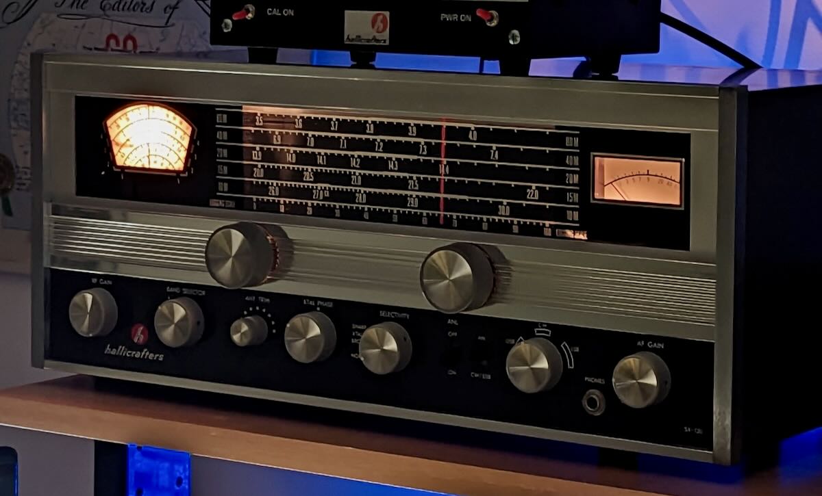
Recently my “radio brother” Bruno F6CRN gave me a vintage Hallicrafters SX-130 from the mid seventies. The receiver was extremely nice for a 55 years old rig, had never seen a soldering iron for repair and had original Hallicrafters tubes but was not performing very well.
After some research , I found a solder joint between 2 pins of a tube support, and this solder joint was done during manufacture!

After alignment, the receiver performed relatively well for that kind of somewhat low cost receiver.
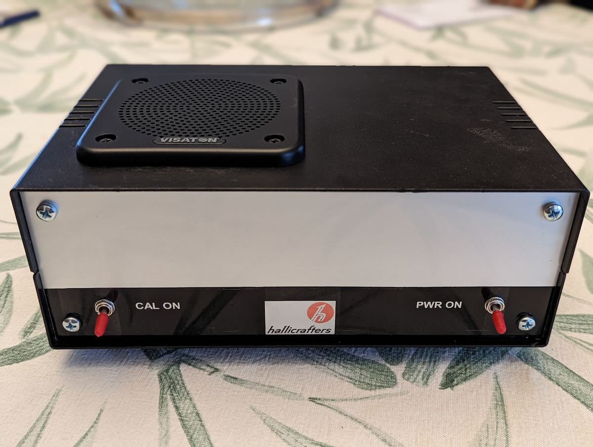
These low to mid cost receivers, made by Hallicrafters, Hammarlund and National are single conversion design, with a low frequency IF near 455 kHz or 1.6 MHz. Their frequency calibration is rather poor, they drift, and have poor image rejection, but can perform reasonably well on AM, and also on SSB and CW on the lower bands. Generally, these American receivers are powered on 117 VAC, have no built in speaker, and the crystal calibrator was optional or an outboard accessory.
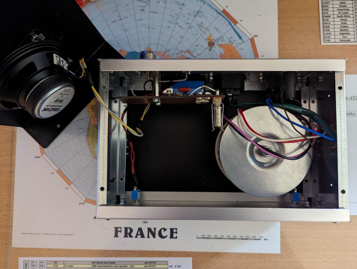
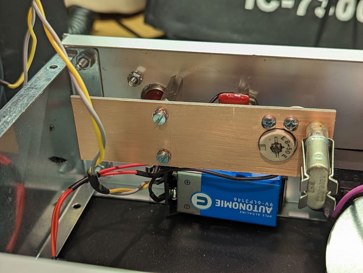
To use it, I decided to built a small console with an isolation transformer to reduce the European mains from 230 to 117 VAC, a good quality 4 ohms speaker, and a 1 MHz calibrator Manhattan style.
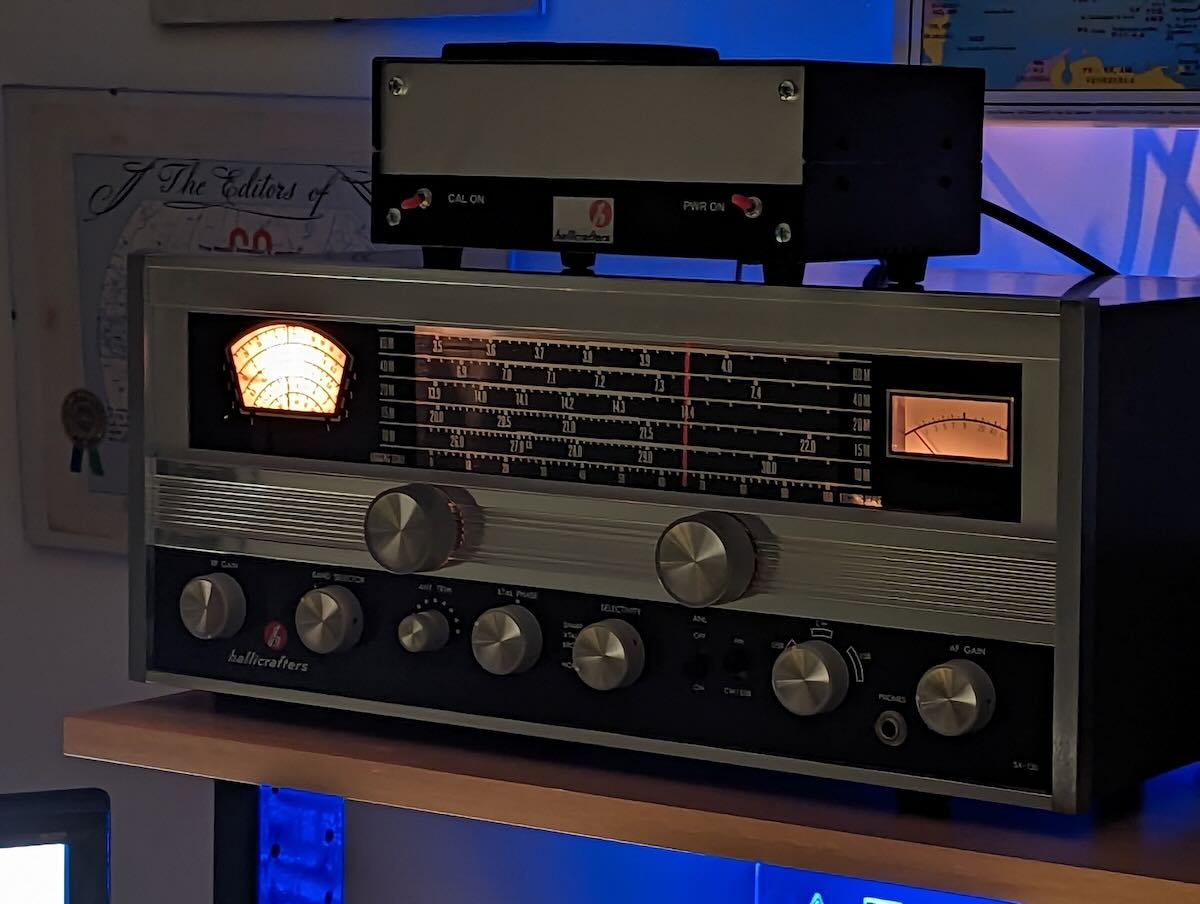
With this console, the receiver looks great, give a taste of the few remaining broadcast stations and warm the shack.
Oh wow! What a beautiful SX-130, Georges! What a great friend you have in Bruno.
Thank you for sharing!
Regarding QRN, in the early 1980s I got interested in loop antennas. Having access to a well-stocked engineering library, I collected a lot of information from which I was able to construct some respectable receiving antennas. Initially my antennas were restricted to LW and MW. About 10 years ago I started extrapolating the design into the shortwaves. My current antenna is described in the SWLing Post archives at
https://swling.com/blog/2021/10/bobs-updated-passive-resonant-transformer-coupled-loop-antenna-for-shortwave/
This will mitigate most of my QRN, which seems to be most sever in the shortwave spectrum. I really need to mechanically adapt it to my LW/MW design which permits 90-degree vertical positioning in addition to its current 360-degree lateral rotation.
Thanks for the interesting SP-600 info Bob. Too bad about your local QRN which is obviously man made. If you haven’t already, please look for the articles on the web by John Doty on low noise receiving antennas. I found these articles many years ago and experimented quite a bit with low noise antennas and was very successful. I never use my amateur transmitting antennas for receiving any more. The S/N ratio for the low noise receive antennas is vastly superior to the transmit antennas, and a really bad day is a noise floor of S-3. This noise level would typically be an S-9+ on any of my transmitting antennas.
Regards,
Frank
Frank and Georges,
I agree on the Hammarlund quality. I still have three, count ‘em three SP-600s, which I got from a ham buddy back in the mid-1970s. I have rehabbed all of them. One is in the shack on line; the other two are stacked up in the basement. These cover 540 kHz to 54 MHz over six bands. Each band has alignment caps for the oscillator, converter, and the two RF stages. That’s 48 adjustments for the RF section. The radios are double conversion on the top three bands, so there’s another handful of slugs in the IF. The embossed metal dial markings are about as spot on as you can get. Yes on the Hammarlund cap quality. Further, they are quite linear, so you can make linear interpolation between any two points with good accuracy. I installed 100 kHz calibrators in place of the crystal oscillators. Years ago I worked for Watkins-Johnson Co. in Rockville, MD. They made a digital readout specifically for the SP-600, but I have never been able to find one.
A few years ago I undertook a project to restore a batch of similar GE 5-transistor AM radios from the late 1950s. They had no alignment points at the low end of the band. That’s when I discovered the trick of changing the IF frequency to match the difference between the oscillator and converter at the low end.
I also have mint Hallicrafters S-38E, S-40B, and a National NC-109. I don’t have a clue where to start aligning a Tecsun. The QRN in my area has just about killed SWLing.
Regards,
Bob
Bob – excellent comments. You have just confirmed what I have “discovered” after aligning many tube “boat anchor” receivers of bygone days. I would like to note that the Hammarlund receivers that I have aligned are the most accurate by far after alignment. Probably this is because Hammarlund manufactured its own variable capacitors, and the alignment coil/capacitor combo for each band was more carefully chosen.
Regards,
Frank
W7YAZ
Restoring these beloved old boat anchors is a marvelous pastime. Understand the dial was designed on a prototype by the manufacturer, and production receivers were manufactured to that standard. I have found that disregarding the manufacturer’s alignment instructions, particularly with less expensive receivers can sometimes lead to better selectivity and sensitivity. This is due primarily to the uneven tracking of the variable capacitor gangs and corresponding lack of converter and RF stage adjustment points at the low end of each band.
1. For example, RF alignment points are most often selected about 10 percent in from each end of the band rather than at the end. This provides better tracking at the center of the band with some degradation at the extreme ends. A poorly calibrated dial can sometimes be improved by mechanically adjusting the zero (stop) point, or changing the upper and lower RF alignment points.
2. For economic reasons, many receivers don’t have converter adjustments at the lower end of the band, and the actual frequency difference between the oscillator and converter stage at this point may no longer be the customary 455 kHz. I have found the difference to be as much as 5- to 10-kHz. In order to compensate for this, first determine what the actual difference frequency is at the low end and retune the IF to that frequency. Then, realign the oscillator and converter at high end to the new IF frequency.
A multi-band, digital receiver, a cheap RF generator and DVM are all that is necessary to determine signal and oscillator frequencies and output.
Bob
Hi Bob,
Thanks for your comments.
I made a few alignments. Generally high grade receivers like the Collins 51-S1, if the band crystals have not drifted too much, are easy to align.
But for low cost receivers, even like the Yaesu FRG-7, you must do compromise.
Best regards
Georges F6DFZ
John – if you look at the schematic of the SX-99 and the S-40B along with the underside component placing, you can see that the SX-99 is essentially the same circuit with S-meter and Xtal filter circuits added.
Frank
Very interesting. The problem (as you probably know) is what MHz points to use at the top and bottom of a given band to adjust the frequency calibration. I have found that if you use the extreme endpoint frequencies, the center of the band may be out. I usually come 1 or 2 MHz in from the main tuning endpoint marks to do this adjustment which usually makes the center part of the band more accurate if tracking is not optimum using the radio’s manual recommendations. This SX-130 is essentially an updated SX-110 circuit wise. The SX-110 was an improved SX-99 and the 99 was an improvement on the old S-40 series.
Frank
The SX-99 is more an upgrade of the SX-25, which had a S Meter and Xtal filter. The S-40 did not and was in the series S-20R -> S-40 -> S-85.
John
Hi Frank,
At first I used a 100 kHz calibrator, but the precision of the dial made it difficult to find the right calibration point.
So now I use a 1 MHz calibrator with the following procedure : if I use the bandspread dial, I set the dial to a multiple of 1 MHz (4 MHz, 7 MHz, 14 MHz…) then use the main dial to zero beat. If I use the main dial, I set the dial to a multiple of 1 MHz, then use the bandspread dial to get zero beat ; the bandspread dial can be used as a fine tuning.
Best regard,
Georges F6DFZ
Georges – nice report. If you can find someone that can touch up the alignment of that SX-130 (a manual will be required which can be found on line), it can make a world of difference in the calibration, sensitivity, and overall performance. Over time and/or storage, and of course, the heat generated from usage, causes the alignment of these old tube rigs to change. I just recently aligned an SX-99 and an SX-122 for a friend and the difference was nothing short of dramatic. I think there was a rare version of your SX-130 called an SX-133 which had not only the amateur bands but also the major shortwave broadcast bands on the bandspread dial.
Regards and happy holidays!
Frank
W7YAZ
Hi Frank, I did the alignment myself. Sensitivity is good, and frequency tracking was improved, but frequency calibration remains poor. The SX133 is mainly the same, but the bandspread includes some broadcast bands. It also allows the use of an internal optional 100 kHz calibrator.
Best regards,
Georges F6DFZ
Nice!
Glory to Ukraine !
Hear, hear!