Many thanks to SWLing Post contributor, Bill Hemphill, who shares the following guest post:
Remote Antenna Switching Remote Low Noise Amplifier Switching and Switching an Antenna and Audio Between Two Radios
by Bill Hemphill, WD9EQD
Remote Antenna Switching
I have two YouLoop Antennas. I had been placing them at right angles to each other. I would then put one of them on the AirSpy software defined radio. But manually switching from one antenna to the other was a real pain. If only there were a way to electrically switch between the two antennas.
It would be nice to place the antennas remotely from the radio (and computers) and then have some sort of remote switch that would select an antenna and then a single feed line to the radio. It was research time.
The YouLoop and the Airspy both use SMA connectors. An SMA switch would be required. A little research and I came across the following small board that can switch between two SMA antennas:
 From Amazon Description: 50 Ohms RF Switch Module, 3-5V Remote Wireless RF Switch Single Pole Double Throw Board Input Output Impedance for DIY Electric Doors (HMC349)
This board is perfect for RECEIVE only projects. Apply 5V to the board and then 5V to the VCC (control pin) to switch from RF1 to RF2.
Now that I had the SMA switch module, a way to actually do the switch remotely was required. Maybe WI-Fi or Bluetooth module would do the trick. I found a nice Wi-Fi module on Amazon that looked like it would do the trick:
 Amazon Description: DIYmalls SV Safe Low Voltage WiFi Wireless Switch Module DC 5V-24V Phone APP Remote Control Smart Home for Amazon Alexa Google Assistant
But do I really want to use a phone app to switch antennas. Further investigation discovered a really neat module that uses a Car Fob type control:
 Amazon Description: RODOT Mini Relay Wireless Switch, 433Mhz Remote Control Relay Switch, DC 6V 12V 24V 1CH Channel Relay Wireless Secure RF Transmitter and Receiver kit, Momentary Toggle Latched Mode
BIngo!! I could just press a button and switch antennas. But a problem quickly arose. I hadn’t fully read the description of the RODOT switch:
The blue output wire is ALWAYS Vcc (input voltage)! The device only switches the ground.
So the RODOT switches the ground but the HMC349 uses positive voltage to switch. OOPS. Next step was to place a latching relay to take the on/off ground and convert it to on/off positive. Again, another nice board was found:
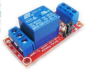
 Amazon Description: HiLetgo 2pcs 5V One Channel Relay Module Relay Switch with OPTO Isolation High Low Level Trigger
The nice thing about the Relay Module is that it can be latched either High or Low, so the RODOT switching ground can be used to latch the relay and then provide a positive voltage to the HMC349 antenna switch.
All modules are powered by 5V. There are other modules available that use higher voltages. But I wanted to be able to use a 5V power source for everything.
I learned a quick lesson on the first layout I did. I had directly connected the antenna cables to the HMC349 module. A quick accidental side yank on one of the antenna cables and the SMA connector tore off the board. A replacement board and some quick wiring and I had a workable antenna switch that with the press of the car fob button, either antenna could be selected.
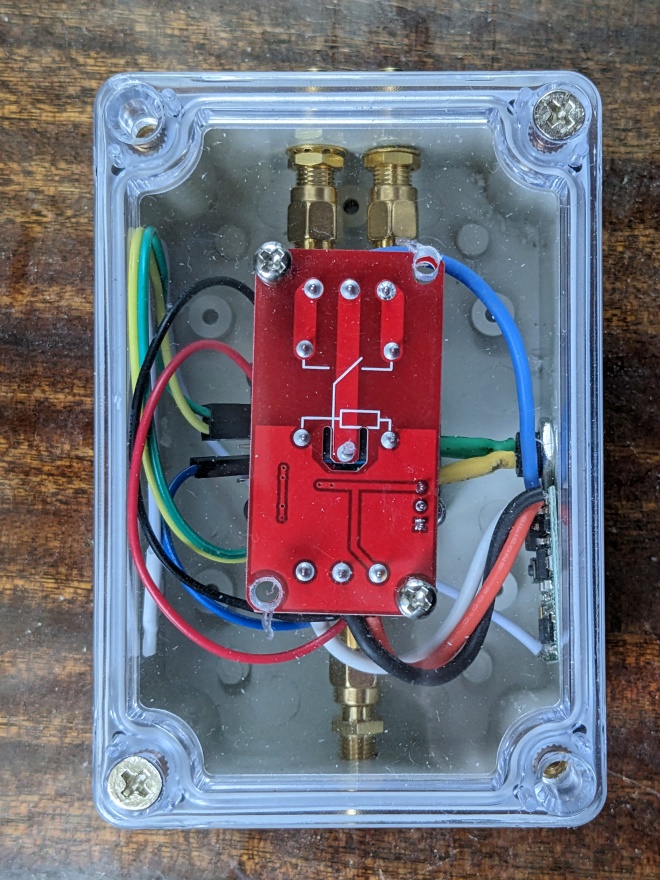
I found a nice small plastic box that allowed for the HMC349 module to be suspended between SMA bulkhead connectors. By using bulkhead connectors, there is no strain placed on the HMC349 connectors. The relay module was attached to the box lid. The modules are mounted using brass standoffs. The finished box is about 3”x4”x 2” high. Either battery or a 5V wall module can be used to power it.

 Overall, I’m quite pleased with the results. I find that sometimes switching antennas (and their orientation) can make a big improvement in the signals. Other times, there’s very little difference.
Remote Low Noise Amplifier along with Antenna Switching
Now that the antennas can be switched, it would be nice if a Low Noise Amplifier could be switched in and out of the circuit. Something like the Lana HF Barebones LNA made by NooElec:
 For testing purposes, I first did a quick layout of just using one antenna with the ability to switch the LNA in and out. Note: I took a gamble on hooking the antenna cables directly to the HMC349 modules. Luckily, the SMA connects didn’t tear off the boards.
 Two HMC349 modules are used. The first module selects the bypass or the LNA. Likewise, the second module also selects either the bypass or LNA. Note that the second module is turned upside down so that the switches match up when activated. Two modules were used so that the LNA is totally switched out of the circuit.
One part was still bugging me – that was the need to use that external relay to account for the fact the remote module switched the common and not the hot. A little more research and a combination relay/remote module was located:
 Amazon Description: DieseRC Wireless Remote Control Switch 433Mhz 5V 12V 24V 1 Channel Radio Control Relay Receiver with 2 Transmitters keyfobs Potential-Free Contacts Relay Controller
By using this, the circuit was cleaned up a little bit.
The ultimate goal was to have a box that two antennas would be connected to and then pressing the first button on the remote, an antenna would be selected. The second button would then switch the LNA in and out of the circuit.
I found a nice plastic box that had a mounting plate in it where all the components could be mounted to.
I first laid out the components to determine spacing, etc.:
 There are two Remote Relay boards and three HMC349 SMA switch modules. At the top is a board used for providing power to all the boards.
Components get mounted to the base board using brass standoffs.
 Testing the exact spacing for the HMC349 boards and the connections to the bulkhead SMA’s:
 Final wiring (I know – it’s messy, but it works):
 Short pieces of SMA cable is used to connect the LNA to the HMC349 modules.
The antenna switch described earlier and the Antenna & LNA switch side by side:
 Switching an Antenna and Audio Between Two Radios
I’m always fascinated when someone does a test between Radio A and Radio B. An attempt is made to use similar antennas, similar audio setting and then the same radio station. This got me to thinking that wouldn’t it be nice to be able to switch an antenna between two radio and at the same time switch the audio out from the radio. Thus, only the audio from the radio connected to the antenna would be heard. This would allow for instant comparison. The finished box would have a connection for the antenna, two connections out to go to the two radios. It would also have two 1/8” audio jacks in that come from the radios and a 1/8” audio jack out. Pressing the button on the remote would switch the antenna from Radio A to Radio B and at the same time switch the audio out so that only the audio from the selected radio is heard. Pressing the button on the remote again would reverse the radios.
Two relays were used to totally isolate the audio. Only mono audio is used. One relay switches the audio ground and the other relay switches the audio. Not sure if the audio ground really needed switching or not. Just wanted to ensure that audio didn’t bleed from one radio to the other.
 One SMA for the antenna and two SMA’s to go to the two radios:
1/8” audio jacks:
 Note that the Radio/Audio switcher can be daisy chained with the LNA/Antenna switching box. This would allow for selecting Antenna A or B, with or without LNA and Radio A or B.
Still To-Do is to add LED’s so that I can visually tell which Radio and Audio is selected.
Conclusion
I’ve had a lot fun making these. It brought back a lot of memories of when I was a kid and would build things. It’s really neat that there are all sorts of small modules that can be purchased for very reasonable prices. These modules almost allow for plug and play. Just need a little bit of interfacing to make all sorts of interesting projects.
Please note: All Amazon links are affiliate links and support the SWLing Post at no cost to you.


The datasheet for the HMC349 says it is “specified from 100 MHz to 4 GHz”. Did you find losses for the SW bands frequencies? I saw there are similar modules but using HMC849 chips, which are “DC to 6GHz”, maybe they’ll be better?…
Depends on which HMC-349 datasheet you look at. The one from Hittite Microwave Corporation says DC to 4Ghz. Others say 0.1 GHZ to 4 Ghz. I would think that it would work fine on the lower frequencies. While I haven’t (and don’t have the equip) to measure losses, I haven’t noticed any great loss when using the antenna direct to the radio and having it go through the switch. I’m sure there are some losses. I may be getting more loses through all the connectors than through the switch. I have to see if any of my ham friends have the equipment to actually measure it.
73
Bill WD9EQD
Smithville, NJ
Very enjoyable post, Thanks for sharing this. More projects and technical writings please.
Thank you for providing a thoughtful work around to a sometimes difficult problem. Now if she who’s in charge of the cash flow can be convinced of the absolute necessity of this device to the safe running of the grant estate we will whip out the old soldering iron.
He who dances with Rottweilers!
I used manual switching with BNC patch panels. With multiple antennas and receivers, this was convenient. The antennas and receivers were on separate panels so isolated when all patch cords were removed. The active whip antenna had 4 outputs, all on the panel. The patch cords had the outer ring removed on the BNC connector at one end, so simple push or pull to connect or disconnect.
Thanks for taking the time to document all this, including the good pictures.
Very cool! Thanks for posting. If you get a chance to produce a block/wiring diagram with components/sourcing that would be much appreciated.
That all looks very complicated.
I used to do antenna switching using simple coaxial relays. Not too cheap but they have a good performance and very simple to switch using just a DC power wire.