Many thanks to SWLing Post contributor, Bob Colegrove, for the following guest post:
Remembering the Radio Shack TRFs
As recalled by Bob Colegrove

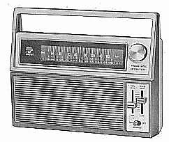
There has always been an interest in DXing on the cheap. At the same time, most of us don’t want to sacrifice any more capability than necessary. In the late 1970s and the early 1980s, Radio Shack provided an attractive answer to this conundrum for medium wave DXers. These were identified respectively by their Radio Shack stock numbers 12-655 and subsequently the 12-656A. I remember them being very popular among National Radio Club members of the time.
These radios were commonly known by their sobriquet “TRF.” Initially applied by Radio Shack itself, the term stuck. TRF stands for tuned radio frequency receiver. In the early days of radio, the term referred to the necessity for the operator to manually put an RF amplifier stage on frequency by adjusting the value of a variable capacitor or inductor. As amplifier stages became cascaded in two or three stages, this became a real problem, as each stage had to produce the correct frequency before anything could be heard. Eventually, designers hit on the idea of mechanically connecting all the RF stages together so tuning could be accomplished with a single knob.
Fast forward to the standard AM radios of a later generation. Entry level (read cheap) radios were limited to two stages consisting of a converter and an oscillator. This was standard design practice during the vacuum tube and transistor eras. Better, more sensitive radios added a third stage, an RF amplifier operating ahead of the converter stage. Obviously, this required more circuitry and, consequently, more expense.
Enter the Radio Shack TRFs. The term TRF was a throwback to the days of the tuned radio frequency radios and referred specifically to Radio Shack’s addition of an extra RF amplifier ahead of the converter stage. The TRFs were by no means the first radios to have this feature, but they were obviously marketed to folks who wanted longer than normal distance reception. Further, the radios were AM only uncompromised by FM circuitry, which would have to be integrated into the design and provide a distraction at best and a performance compromise at worst.
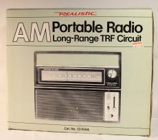
I didn’t discover these treasures until late in their production cycle. Consequently, my comments are mostly focused on the 12-656A. In later times, the -656A retailed for $34.95. On final clearance this dropped to $25, and I snapped up several for my friends and my own tinkering. The internal layout was not especially good for repair or modification, but at least was well within this enthusiast’s capability.
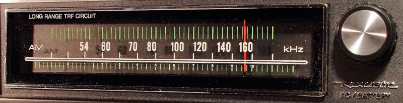
The picture below shows the dial of the -656A. The radio was designed prior to the expansion of the AM broadcast band to 1700 kHz; thus, it is only specified to cover 520 kHz through 1620 kHz. Although I don’t recall ever having tried it, the circuitry could possibly be coaxed to 1700 kHz. On one of my “hot rod” units, I replaced the silk-screened dial with a plain piece of Plexiglas backed with a hand-calibrated dial, which permitted accurate calibrations for 10-kHz channel identification. The tuning knob and dial cord mechanism work very well right out of the box.
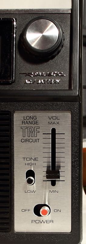
The controls are aligned along the right front side of the radio. Below the tuning knob are tone and volume controls followed by an off/on switch. The 655 is similar, except the tone switch is replaced by a slider potentiometer like the volume control. In retrospect, the off/on switch should have been recessed into the front panel, as it is easy to accidentally turn on the radio with the protrusion of the switch.
The back of the cabinet (below) features standard 1/8” phone jacks for earphones (left) and an external antenna (right). The TRFs may be powered by either four C cells or from 115-Vac mains. Rather than having a separate 6-Vdc wall wart, the ac power supply components, cord and all, are contained inside the radio. For storage, the power cord is simply wrapped up in its own compartment next to the battery compartment.

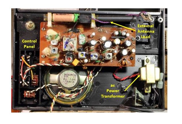
Below is a tinker’s view of the innards of a -656A. Could the box have been made smaller? Obviously, one could replace the internal ac power components with a wall wart. Perhaps the C batteries could be replaced with AAs. Problem is with the speaker. The PC board hides a large drum for the tuning mechanism. Given the smooth tuning and large dial, the tuning arrangement is not something I would compromise. So, stacking the speaker with the PC board would require a much thicker box.
The external antenna uses the standard approach of a small transfer coil wrapped around the ferrite bar for signal transfer. Just as an aside, keep in mind for any long- or medium-wave radio having an external antenna coupled to the internal ferrite bar, the ferrite bar will remain active with the external antenna attached. The external antenna is effective only to the extent that the phase and amplitude of its signal compliment or reduce that produced by the ferrite loop.
In addition to two intermediate frequency (IF) stages, the circuitry includes a 455 kHz ceramic filter in the base circuit of the first IF stage. This provides very good selectivity. Never satisfied the way things are, when I first got these radios, I duplicated a third IF stage in one of the units. The result was a nice tight bandwidth still providing good audio.
The “improvements” in the -656A seem to be focused on the reduction of production costs. I’ve already mentioned the tone switch for one. Another example is the replacement of discrete components in the -655’s audio amplifier with a whopping 0.5-watt integrated circuit in the 656A. Having no way to make a performance comparison, I will say my experience with the -656A is that it is still a very hot radio.
The TRFs filled a relatively minor marketing niche, namely DXing enthusiasts and perhaps a small number of expatriates who wanted to listen to broadcasts from their old hometowns. The format evolution of medium wave broadcasting was already well on the way toward news-talk-ethnic broadcasting, and the appeal to rock ‘n rollers or virtually any music lovers just wasn’t there. A sensitive radio had to include an FM band. So, the TRFs faded into history sometime in the early ‘80s.
Enter the long-distance “superadios,” notably General Electric’s Superadios I, II, and III in the 1990s. Radio Shack itself produced a clone-like Optimus 12-603. The “super” by that time referred more to the audio quality than the sensitivity. This later generation featured two higher-quality speakers packaged in a cabinet with somewhat better acoustics, separate base and treble controls, all driven by a higher-powered audio amplifier.
Having worked in the industry for a couple years as an assembler, I have never been convinced that inclusion of multiple band coverage does not result in some performance compromise. Radios such as the TRFs have a special appeal to me. The General Electric P780 is another well-regarded example of an AM-only, high-sensitivity, radio. Maybe you have a favorite of your own. If you’re into tinkering, and even if you’re not, a functional TRF or such radio can provide a lot of cheap entertainment.