
Many thanks to SWLing Post contributor, Dan Brown (W1DAN) for the following guest post:
A WRNO Worldwide Transmitter Site Visit
by Dan Brown W1DAN
![]()
The opportunity to visit a shortwave transmitter site does not come to me often. It did during the summer of 2009, so I jumped at the chance. Along with friend Bob K5IQ, we visited the WRNO Worldwide transmitter in New Orleans and were guests of Chief Engineer Larry Thom. He kindly showed us the transmitter site, talked of the interesting technical story of the rebirth of the WRNO Worldwide transmitter site and displayed some of his ingenious technical adaptations to create a smooth running plant.
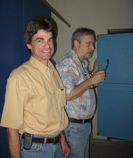
Larry smiles as Bob Is amazed at the innards of the WRNO HF transmitter!
Originally put on the air as the first commercial shortwave station by local New Orleans radio owner Joe Costello in 1982, and purchased by Dr. Robert Mawire of Good News Outreach in 2001, the now non-profit religious station is fed from Fort Worth Texas studios. The transmitter, still in the New Orleans suburb of Marrero, primarily operates at 7505KHz and can be heard evenings from 1200 to 1400UTC (8PM to 10PM EST).
The plant’s main feature is an Electronic Corporation (Elcor) SW50/3S fifty kilowatt transmitter (see Figure 1). Built in Costa Rica, this transmitter feeds a TCI 516-3 log periodic antenna that was a mainstay of the Joe Costello rock and roll days of WRNO Worldwide. The transmitter is plate modulated and uses time-tested circuitry such as vacuum tubes, relay control and crystal oscillators as compared to solid-state modulators and microprocessor control. The system sends effectively a 3 megawatt signal around the world.
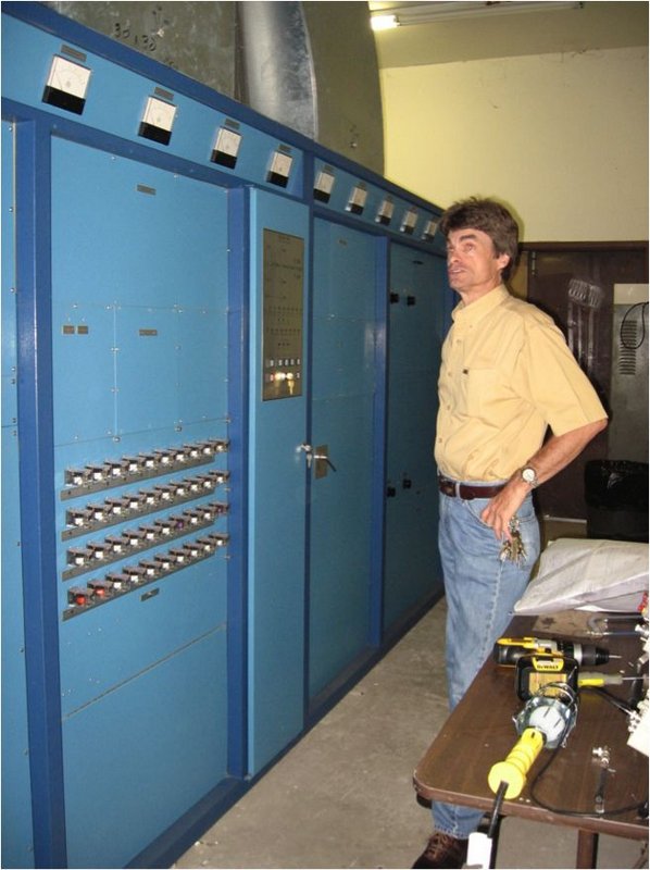
Figure 1. Larry describes the Elcor transmitter. In the foreground is the control cabinet with the control relays out front for easy access.
Interestingly, Larry incorporates baking thermometers to measure the exhaust air temperature. Cheap and efficient! In order to get the transmitter to work properly two interesting adaptations were required. The first was the transformation of the output impedance from 50 ohms to 75 ohms. This was done using a custom Elcor transformer as shown in Figure 2.
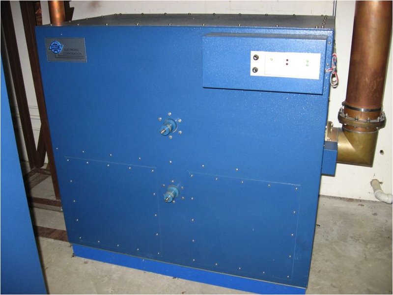
Figure 2. Elcor custom RF transformer
This impedance transformer feeds a TCI high power BALUN (BALanced to UNbalanced transformer, but here run in reverse), as the TCI antenna requires a balanced feed. The BALUN is a commercial TCI unit and is shown in Figure 3.
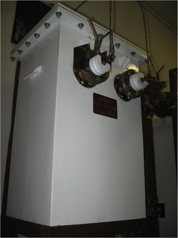
Figure 3. TCI BALUN takes unbalanced RF from transmitter and feeds the 300 ohm balanced TCI Antenna. How big is your BALUN?
Another interesting adaptation became necessary, as the transmitter would often trip the main breaker when it was placed on the air. This problem was due to the high inrush current that would occur when the high voltage power supply was energized. Larry went to Grainger supply and bought high power heating elements and time delay relay. He inserted this in the primary three-phase feed to the power supply. Now, when the supply is switched on, the heating element provides a series resistance (and heats up for a moment) to absorb the inrush. After a short time, the relay would jump the element out to allow full current to feed to power supply (see figure 4).
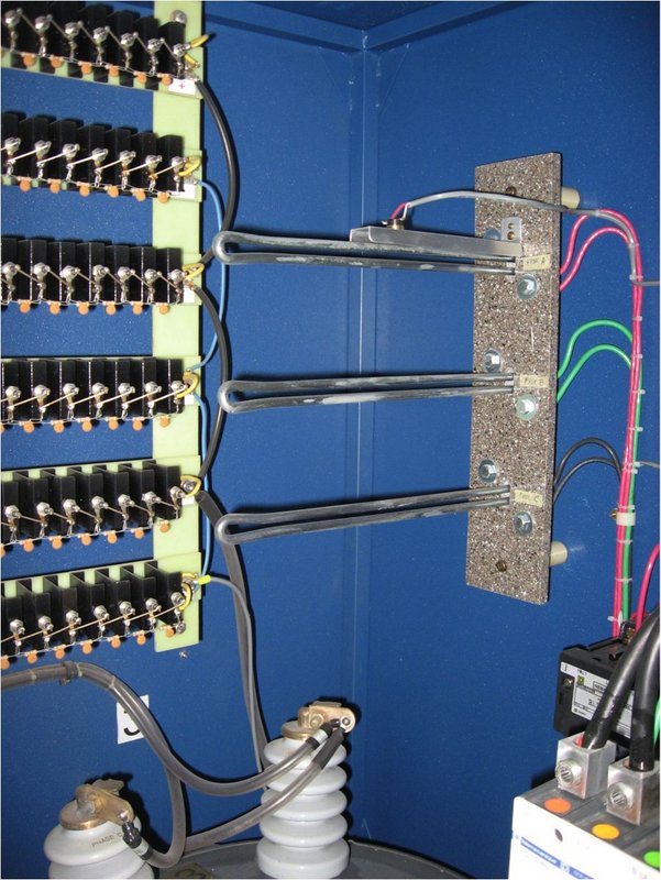
Figure 4. Heating elements on the upper right inside wall of the power supply limit inrush current.
Another small problem with the transmitter was the drift of the master oscillator. Larry had Elcor build a synthesized oscillator for the transmitter to reduce the drift (figure 5).
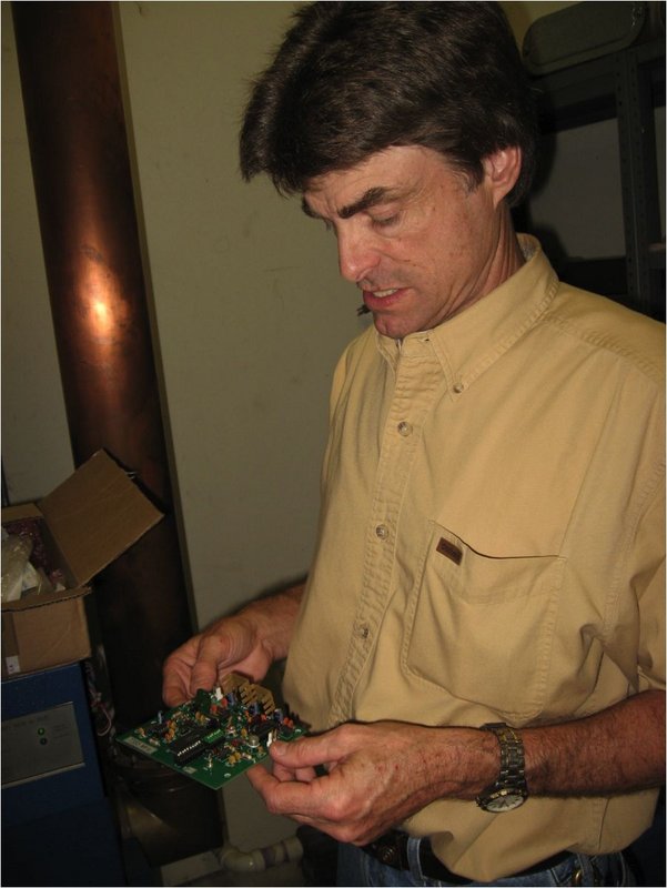
Figure 5. Larry with new synthesized reference oscillator module
WWL-AM has their 50Kw transmitter on 870KHz near the WRNO Worldwide transmitter. Due to this proximity they send a hefty signal into the WRNO antenna and thus into the transmitter. Here these two signals can mix together to form a soup of audio in the WRNO transmitter tank circuit. A notch filter was constructed to reduce WWL-870’s AM signal (Figure 6).
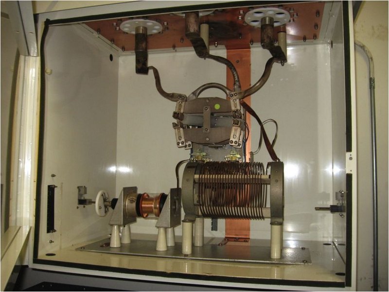
Figure 6. WWL 870KHz notch filter
During the visit, Bob and I listened to Larry’s stories and snooped around the building. We spotted a Vintage Radio Labs “Globe King” 500A that is slated as an emergency backup transmitter (Figure 7). It is rumored that this classic redesign of an older transmitter marketed in the 1990’s was a poor copy of the original 1950’s era World Radio Labs Globe King transmitter. Larry states that this transmitter is serial number 1. Only a few were built.
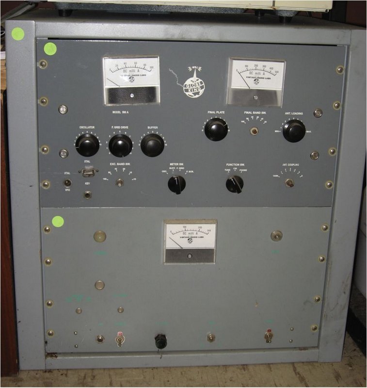
Figure 7. A Vintage Radio Labs “Globe King 500A” backup transmitter (SN1?). The crystal is for the old frequency of 7355 kHz
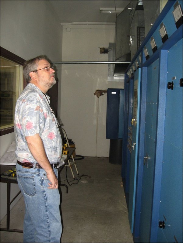
Figure 8. Bob K5IQ dreams of calling “CQ DX!” on a 50Kw rig and a 14db antenna
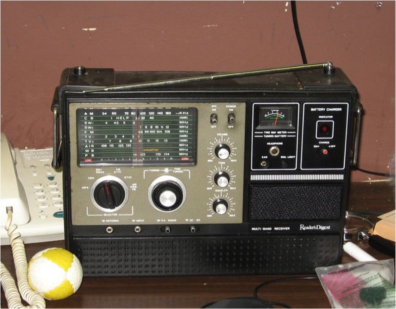
Figure 9. The Official FCC-approved Reader’s Digest reference modulation monitor!
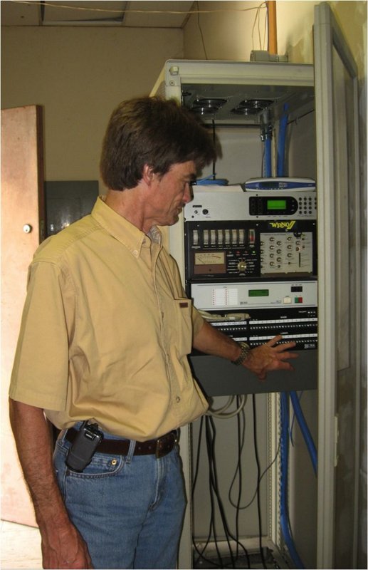
Figure 10. The audio and control rack. Audio is fed via a T1 line from Texas to the Telos ISDN decoder, then to the Optimod 9000A audio processor (an original from the Joe Costello days). The remote control is a Burk unit that allows the studio folks in Texas to control the transmitter.
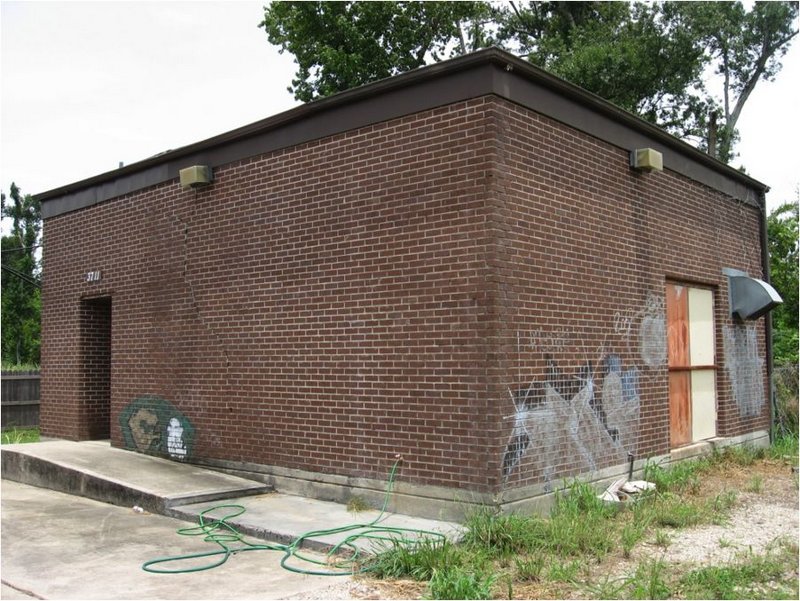
Figure 11. The Marrero, LA transmitter shack heard ‘round the world!
An article I wrote on the re-birth of WRNO Worldwide for the August 2007 Monitoring Times magazine, and the fact that I was on vacation in New Orleans prompted this visit. It is always fun to visit a transmitter site to see how things are done. Thanks to Bob K5IQ for driving!
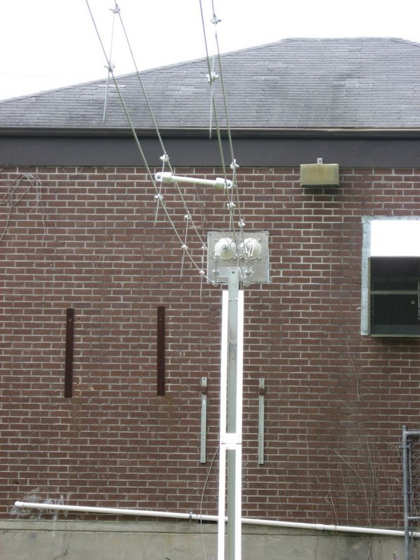
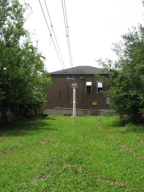
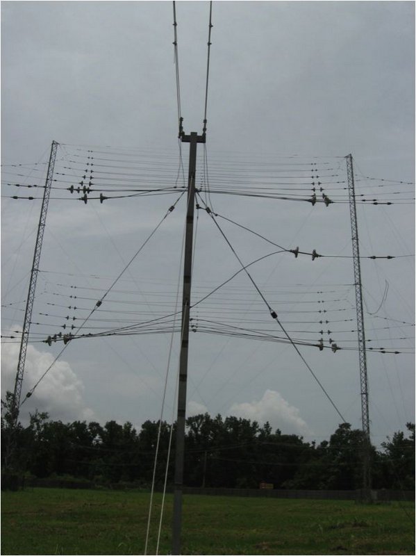
Figure 12. View from the balanced feed point of the TCI 516-3 log periodic antenna 1ith 14db gain aimed at 20 degrees
Here are a few web-links of interest:
- http://www.wrnoworldwide.com
- https://en.wikipedia.org/wiki/WRNO_(shortwave)
- http://americanradiohistory.com/Archive-Popular-Communications/80s/Popular-Communications-1989-12.pdf
Copyright
Dan Brown, W1DAN
Created 09/2009
Updated 07/2016
Wow–many thanks for sharing your tour of WRNO with us, Dan! My-oh-my how I’d love to have that 14db gain log periodic at my disposal! Great facility!
1200 to 1400UTC (8PM to 10PM EST)
Incorrect posting in your WRNO offering
Great pictures and post.
That indeed looks like at least part of the ill-fated Globe King 500D that was indeed a very poorly implemented 90s creation.
Leo Meyerson’s original Globe Kings were really nice rigs (I still have two)
This is a really interesting post Dan and Thomas. Thanks for making the visit, taking the photos and posting such an informative post, Dan. Thomas, I’ll put a link to this in my own blog, just in case a few missed it.