
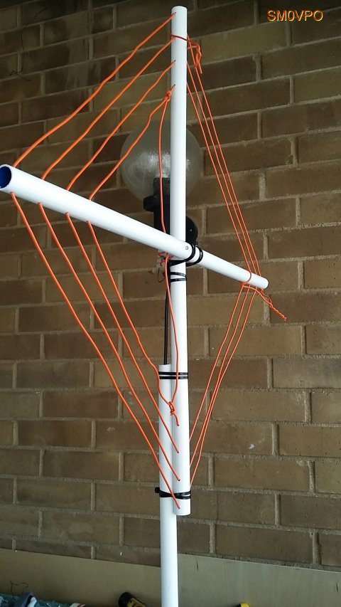
The completed 20 meter loop antenna.
A few days ago, SWLing Post contributor, Robert Gulley (AK3Q), pointed me to an excellent website by Harry Lythall (SM0VPO) which is chock-full of various homebrew radio projects. In particular, we both were impressed with Harry’s 20 Meter Loop Antenna–it’s such a simple project and requires no special order components. In fact, all of the components (save, perhaps, the antenna connector) can be purchased at a DIY store.
I reached out to Harry and he has kindly allowed me to republish this project as a guest post:
20m Loop Antenna
by Harry Lythall – SM0VPO
Introduction
I recently saw that my 80m (3.5MHz) loop (or frame) antenna has been really popular, and that there are loads of other radio amateurs who have taken my design and “ran with it” to produce variations that all have some great improvement. There have been many in-depth tests and simulations, all with exceedingly good results and reports. This is exactly what I am aiming for with my homepages – free information for all and my designs being improved upon. That way we all win 🙂
One small point all variations have in common is the need for an expensive tuning capacitor and a very restricted RF power level. Of course, you can throw money at the problem, but for me this hurts. I got to thinking that there must be a way of adjusting the design a little and finding another technique to tune the antenna, and to make the best use of the little radio transceiver I have in Sweden, given the limited space.
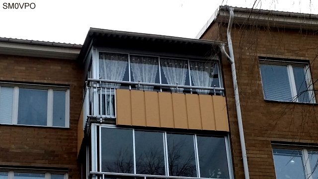
My limited space apartment.
As you can see there is not much opportunity for grand antennas. And to add to this, the equipment I have in Sweden is also limited to a single 5-Watt unit.

My limited equipment – only 5-Watts.
The Design Thoughts
Today I have no area of land to use for antennas. I have a glassed-in balcony on the 4th floor of an apartment block. I really like the 20m (14MHz) band so I will concentrate on that. I am not really interested in the CW end of the band, except perhaps 14.070MHz for the digimodes. So my requirements are:
- As efficient as possible (useable)
- Small size, also portable so I can use it for field use
- No expensive components, everything available locally
- No TVI, QRM or interference to stereos or computer sound
- Total price less than $2
The antenna I have created is based on my original 3.5MHz loop (or frame) antenna. This time I built it out of scrap components. I cadged (tiggade) some plastic conduit tubes from an electrical contractor at work. The same guy also gave me the remnants of a roll of 2.5mm C.S.A. multi-strand mains cable. That was all I needed.In my junkbox I found no tuning capacitors, but WAIT!! Why do I need to tune the antenna? Once it is tuned I should not need to tune it again, just set the centre-frequency to 14.175MHz. If I can get the Q-factor to around 100 then my useable 3dB bandwidth should be more than 150kHz. That will give me 14.10MHz to 14.25MHz.
Ok, I need a 1-off, preset tuning capacitor. Why not use a Gimmik Capacitor? Just twist two bits of wire together and cut it short to get the resonant frequency I want. So I need to get the coil wound so that there is sufficient cable length and self capacitance to give a resonance of about 14.5MHz without any extra capacitance what-so-ever. That means I need just a few pf. That sounds like a good plan.
Construction
The 15mm Diameter plastic tube I “aquired” were 80cm long. After much trial and error I found that exactly 3 turns, with 2.5cm spacing, gives about 14.9MHz self resonance. The wire support holes are exactly 4cm spaced, beginning 1cm from the end of each tube. The two tubes are fixed into a and X using zip-straps (tie-wraps, buntband). The feed loop is 1/2 turn.

Note the size and position of the feed loop. Also the Gimmik capacitor.
One problem I had with the original loop antenna was that of RF coming back down the cable braid. Using on old FT-101ZD it was possible to feel the RF on the microphone with your lips. The cure for this is to use a balanced feed and at least 5m of RF cable.
I robbed the ferrite ring for the balun from an old ATX computer PSU and made a triflar wound torroidal transformer. That is to say, twist together three lengths of 1mm x 7-strand insulated hookup wire together. Use this to make a 7-turn coil and connect the three coils in series, with four connections. Feed connections (numbered in the picture below) 1 and 3 are connected to to the antenna feed loop. Connect the coaxial cable braid to connection 2, and the coax centre to connection 4. My balun is self-supported on the connection leads.
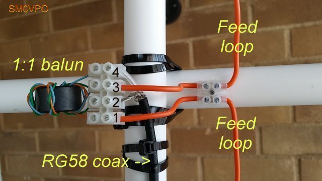
The 1:1 Balun I used.
The coaxial feed cable was found to affect the resonance slightly, so I fed that through an extra bit of tube to make it stay in one place. It works fine.
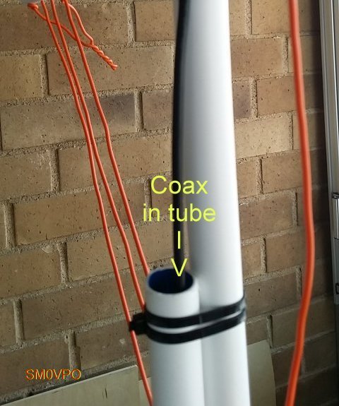
Feeder cable secured in the support tube.
Testing
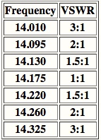
Testing is very easy. I used my GDO-2 to check the middle-turn of the loop for a dip. Twist the two tails together to form the Gimmik capacitor and adjust the length of the twist until the centre-frequency is 14.175MHz. With the GDO you can get it within about 100kHz to 200kHz, but then you can check the VSWR using your HF radio. You can also sweep the band for maximum noise and get a very close approximation.

The Gimmick capacitor.
The centre frequency of my 20m Loop antenna is 14.175MHz, and the VSWR is better than 1.05:1 (I can hardly see any movement on my meter). The Q-factor is somewhere approaching 100. The useable bandwidth is just a little narrower than I would have wished, but the antenna certainly works well and meets all the other criteria. But the slightly less useable bandwidth criterion is at the expense of better performance, and it still allows me to use 14.070MHz, although it is a little quieter down there.
The completed antenna.
Conclusion
No-matter how you play with the figures, the best indoor antenna cannot replace a full-size dipole antenna. But the indoor antenna can give some extra features, such as just reaching out your arm and trimming a little, which you cannot do with a long-wire antenna up a tree out in the garden, especially when it is raining.
This antenna gets me on the air on 14MHz, and it has a useable frequency range. The VSWR is almost perfect at the centre-frequency, and this time I don’t burn my lips on the microphone (not that I am likely to do so with just 5-Watts of power). The design uses no expensive components, in fact the only item I bought was the block-connector for the balun. That cost me US$1.50 for a pair of 12-contact screw-terminals. The construction is ridiculously simple and easy to build.
On the air I can hear traffic on 14.070 digimodes, and from 14.130 to 14.220MHz I have a near-perfect VSWR aqnd good clear reception of SSB. I can also rotate the antenna to cut out rubbish, and most of all, using the Gimmik capacitor I don’t need to re-tune it: it seems temperatore-stable. The weight is less than 500g and when I poke it out of the balcony window the reception improves, the VSWR does not change, and I can make myself heard among the big boys.
I hope that you have some fun building and using this antenna. If you have any ideas for further improving it then please use my forum.
Don’t forget to visit my messageboard if you have any questions about this or any other project. I always look forward to receiving feedback, positive or negative.
Very best regards from Harry Lythall
SM0VPO (QRA = JO89WO), Märsta, Sweden.
EA/SM0VPO (QRA = IM86BS), Nerja, Spain.
Many thanks, Harry, for sharing this excellent project on the SWLing Post!
Post Readers: be sure to check out Harry’s website which is loaded with radio projects of all stripes. You’ll easily spend a few hours digging through his tutorials and downloads. Harry also maintains an alternate mirror server located here.
Side note: I’m impressed with the fact that the main SM0VPO website is actually hosted on a bedside Raspberry Pi computer (running the Linux-based Lighttp server). Very cool!
Check out other homebrew mag loop antenna projects on the SWLing Post by clicking here.
Thanks to Harry for such a great idea! I built my own multiband portable version using a variable capacitor, you can see it in my QRZ page (https://www.qrz.com/db/VA3ITI). Something interesting is that a spiral loop has quite a bit of parasitic capacitance, which may limit your upper frequency. Fewer turns with more separation help, but not as much as you’d imagine.
Hi
Got any detail drwings: Demenions ect.
I live ina small flat and would like a HF antenna ect. Something to build like your one.
Thanks
2E0BSR
Hello Harry.
Thanks very much for your antenna project, it seems to me very smart, and there is high probability that I will try it. Especially that I have very similar location limitations as you have (practically no way to install full size HF antenna like a dipol or a delta). The only thing that is my concern is your voltage balun. Do you believe it would be replaced or paired /supported with current one, even made as coax air-coil? I have personally very little experience in the balun area, but according to the 1980’s article by R. W. Lewallen “Baluns: What they do and how they do it”, the current baluns work better, namely they really make the system balanced, not only give voltage balancing at the antenna feed point, like voltage ones do.
Thanks again for a nice project, especially that it uses Gimmik Capacitor – that is some kind of revelation for me – what a simple and cleaver approach 🙂
Best regards,
Norbert.
I have tried to build this will no luck yet.
I have nothing to measure it, only trying to receive and I can’t even find anything resembling a noise maximum.
It would be nice to have a better picture of this balun, as I suspect that mine is just not that. My cable seem to be much thicker and not as well braided, perhaps I should re-do, but I wonder if my ferriite ring is smaller to make it all more crowded. I just wish you showed the balun up close with at least one more angle!
Also I’m not sure my feed loop is correct.
Many variables here to get wrong.
I noticed that the mast and antenna are joined with cable ties which is fine. I have found however that adding a third piece of the same or similar piece of tubing in a triangular arrangement along with whatever clamping method one chooses including but not limited to the cable ties, the third piece of tubing adds a lot of extra lateral stability to the mast/antenna joint.
Nice antenna project!
Interesting comments about the Gimmick capacitor.
I found it no problem at all to just reach out and give it a “tweek” when i needed to tune it up and down the band a bit. In effect I had coverage of the whole 14.000 to 14.350Mhz band.
I have just finished work on a decent (and cheap 🙂 10KV tuning capacitor that can be adjusted to give a near perfect VSWR on any frequency, although the usable bandwidth is about 75kHz without re-tuning.
Very best regards from Harry Lythall – SM0VPO (EA/SM0VPO)
Hi
The Captcha page to contact you no longer works. Please check yourself you will see that they have shut down the service.
I was going to ask if you could provide some form of search facility for your site. As you are using WordPress, it should be fairly easy to include.
Thanks
Steve
Thanks, Steve! I took out the captcha and encoded the address with HTML character entities. That may work for a while.
There is a search function on each page in the right column. I realize, over time, however as I’ve adapted that sidebar it’s gotten pushed down. I’ll re-arrange!
Cheers,
Thomas
A gimmick capacitor is not easy to replicate. To do that you need to define what the wire size is, what the insulation material is, what the insulation thickness is… And then there is the issue of Q.
The greater the Q factor, the more efficient the loop will be for transmitting purposes. That’s why people pay a premium for good capacitors and large wire in a loop.
A decent variable capacitor with good Q isn’t that expensive and it will have a significant return on the investment.
The point of using a gimmick capacitor in a cheap and cheerful single (partial) band design like this is that it’s zero cost, easy to make, and adjustable/trimmable enough for the desired frequency with nothing more than a rig with output protection & SWR metering. It doesn’t have to be “replicated”, just adjusted to suit.
In fact, in the case of a electrically small tuned loops (particularly fixed-tuned ones), the trick often becomes to get _poor_ enough Q just to get sufficient bandwidth. Case in point: this loop. SM0VPO estimates overall Q to be ~100, which if you’re only focussing on Q doesn’t look that particularly great – but usable bandwidth is only about +- 80kHz of centre; less than 1/2 the 20M band.
And remember, this is an electrically small loop. Efficiency is terrible to start with 😉
If it was a tunable loop rather than a fixed-tune loop, then yeah, the extra few bucks for a proper tuning cap would be well spent. But there’s plenty of designs for those around…