
 Many thanks to SWLing Post contributor, Marty Kraft, who asked that I share the following question with our community:
I’m still working on a receive-only passive hula loop magnetic antenna for my Tecsun PL-660.
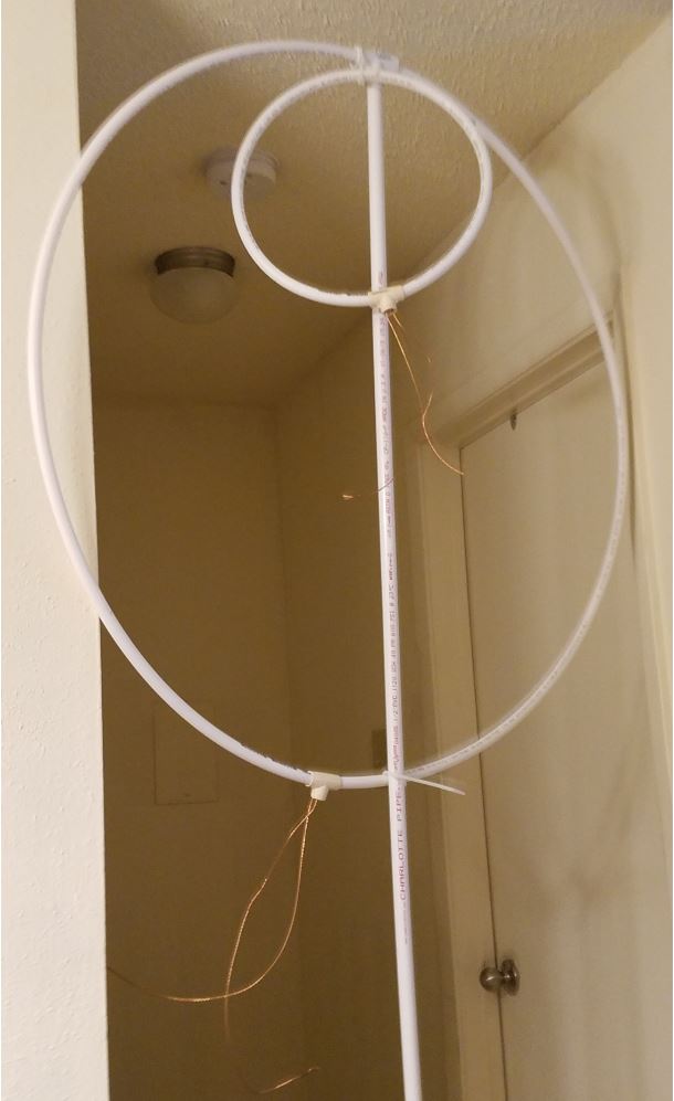
After viewing thousands of YouTube videos (LOL), I built the PVC-pipe structure [you can see in the photo below].
But I need some tech help to finish…
The antenna is 90 inches tall; large loop diameter is 40 inches; and small loop diameter is 17 inches. The wiring is 14 gauge braided.
I plan to put the antenna outside on the porch. Then I’ll run coax from the small loop to the receiver inside and use a 365 pF air variable capacitor to tune the large loop.
My first question is, what’s the best coax to use for the 10-ft run from the small loop to the radio inside? Second, will that 365 pF cap tune the entire 3-30 MHz range?
It’s hot here in Louisiana, so I’d really like to tune the capacitor from inside my apartment, also using coax to connect the cap to the large loop. Will that work? Or does the cap have to connect directly to the large loop?
Any other tips or suggestions? Thanks for the help!
Post Readers: If you have any helpful advice for Marty, please comment!
As in most receiving antennas, a lot of things work that you would think never would. As for the coax, I use Rg59 with F connectors, plenty of this type being used with dishes & TV antennas. I get new rolls from installers. Try it with no coax at the antenna, then try it the way you suggested. remember the signal as you tune & write down frequency & S meter reading from both ways. May surprise what will or won’t work.
+1 to what the 3 earlier comments below have written.
To add my my 50c worth:
* It’s tricky/impossible to get 3-30MHz coverage in a passive tuned loop (and brings up all sorts of design issues with active loops). It /can/ be done, after a fashion – but there’s tradeoffs involved, and without a bit of hands-on experience & loop theory under your belt you’ll likely be disappointed in the outcome. 2 or 3MHz to 17MHz is a more practical and achievable goal for a 1M dia. passive SW loop – you can tune them lower than that, down into the LF band, but you’ll lose higher frequencies; conversely, you can build a smaller loop and gain higher frequencies but lose lower frequencies.
* Whatever coax you choose, make sure it’s proper copper core, not CCS or CCA. That stuff can be remarkably lossy at HF frequencies. For short-ish runs like that (up to about 10M/30′), recently I’ve been using RG-178 or RG-223 quite happily.
* Seconding the recommendation of the loopantennas group on groups.io, with the proviso that it’s common to refer to all types of loops – electrically small, electrically large, resonant, transmitting, receiving, etc – simply as a ‘loop antenna regardless of theory of operation or purpose, and the information isn’t directly transferable between each. You’ll need to learn to differentiate and interpret/apply the knowledge relevant to each type with little prompting.
* Read Chris Trask’s papers (available on his website or the loopantenna groups’ file archives), particularly his varactor-tuned loops. While some of the transformer-winding details are a little unclear, and AM-style varicaps can be hard to get these days (try eBay, and look for substitute part #’s), for my money they’re the best-performing simple-to-build loops around.
* [potential argument starter!] Despite the many claims to the contrary, loops are no substitute for getting your antenna even slightly outside. Any antenna – and loops are no exception – will perform 10x better even out on the verandah than it will in your radio room.
Marty,
lQQks gQQd nice build
re your capacitor question:
1) Mount the cap directly across the gap on the large loop then remote tune from shack with dc motor, I have parts list and image >>n3aaz_qrp_1 at juno dot com<<
2) 365 uF may be too much for 30 meters and up, some 365 uF variables come ganged in two sections and can be wired single section or parallel
3) you can always solder a high quality fixed value cap in series with 365 to lower the total capacitance
4) the cap is the 'weak link' and will arc and spark so caution here even at QRP TX levels several hundred Volts will develop across the capacitor
Reason for remote tuning, single loop antenna have a very high Q as such a very, very narrow band with and must be re-uned often
For best results the Area (A = pi R ^2) ratio of big loop to small should be five to one
Sent to my (N3AAZ) blog at WSPRNET.ORG …
Queen Anne's County ARC (K3QAC) show N tell 2018/03/06:
My homebrew mag loop sets QAC/ARC 40m WSPR record!
K3QAC to DP0GVN (wow good ears at South Pole)
FM19xb to IB59uh
Aprox 13,399 klicks times (0.63) = approx 8,441.4 miles
At two Watts = 4,220.7 miles per Watt
72 73
John
N3AAZ
FM19
ps this loop was located inside our brick library building meeting room in front of 15 or so members, you could literally hear air sacked out of the room when we saw the WSPR NET reports
First of all, passive loops like the one you’re trying to build are mainly used for transmission, while when it comes to reception the activeloops are more widely used, that said and getting back to your loop
The first thing I noticed is that the smaller loop is placed at the top, that’s the reverse of the usual configuration where the coupling loop is placed at the bottom (see http://www.kr1st.com/swlloop.htm) also, the two loops must lay on the same plane (refer to the image at the previous link) and the capacitor MUST sit AT the antenna, not at a remote location since otherwise, stray capacitance will hit you hardly and the antenna just… won’t work.
If you’re going for such an antenna, you’ll need to place the tuning capacitor inside a weatherproof box sitting straight AT the antenna and find a way to remotely adjust it; a way to achieve such a purpose is the one described here http://sm0vpo.altervista.org/antennas/servo.htm in this case the capacitor will be rotated using a cheap “RC Servo” motor which may be controlled (and powered) using a separate cable
A different approach could be using an “untuned” loop like the one described here http://www.kk5jy.net/rx-loop/ it will only require a transformer (see link in the article) which can be easily built using a FairRite #73 binocular core and some wire and which will allow to match the coax impedance to the loop one
Alternatively you may consider building an active loop antenna, there are several designs around, but the most used ones are the following
https://pa0fri.home.xs4all.nl/Ant/Active%20antenna/Active%20receiving%20%20loop%20antenna%20eng.htm
http://www.techlib.com/electronics/antennas.html
the first one is uses a wideband preamplifier, while the second one used a tuned preamplifier; personally I prefer the latter (remote control box version) since the ability to tune the preamp allows to reduce/cut-off undesired, off-band signals, but then it’s up to you
As for the coax cable, if you’re going for a passive antenna, my suggestion is to pick some good quality, low-loss coax, otherwise, with active loops you may even use some lenght of cheap 75 Ohm CATV cable; sincerely, willing to avoid to spend too much for the cable and still have some decent one, I’d pick some lenght of decent RG58, 50 Ohm coax (or RG59 if you want 75 Ohm), but again, that’s just me
Hope to have been of some help
Just in case, given that the antenna will be only used for reception and that you already have the PVC piping loop, I warmly suggest you to consider the idea of building the Wenzel active loop antenna, that is, the one described here http://www.techlib.com/electronics/antennas.html
In your case, you will want to build the “remote controlbox” version of the antenna, that is the one which uses a small remote box containing a potentiometer and a switch and used to tune the loop to the desired frequency range
The electronics (preamplifier) are relatively simple and can be assembled even using a prototype board, and the components are quite cheap and widely available online (mouser and other sites have them)
The only precaution I suggest (from own experience) is to feed the preamp power and control (the cable going from the controlbox to the antenna preamp) using a run of network twisted pair cable (e.g. a “CAT5”) such a cable has the internal wires wrapped in “pairs”, just use one wire from each pair for the desired connection (power, tuning) and connect the other one to ground, this will avoid that the control cable may pick up stray signals and inject them into the preamp
Other than that, given that the power you’ll feed to the preamp (through the cable) is clean enough (you may use a battery or a good, filtered power supply), the antenna will perform really well in the 3 to 30MHz range (and somewhat outside that range) and won’t cost you an arm and a leg 🙂
Marty,
First off, there’s a very active loop antenna group on Groups.io. Suggest you join them and tap into some further advice.
I am not an EE, but I’ve been building passive, resonant loops for over 35 years, everything from 150 kHz thru 23 MHz. It looks like you are trying to make a transformer-type antenna where the large loop is resonated with a capacitor, and fed to the radio via the smaller secondary coil and coax or twisted pair.
The secondary coil really needs to be located coaxially with the larger coil, that is, in the center. Think of the magnetic field generated by the larger coil and capacitor as being shaped like a doughnut with an infinitely small hole. The smaller loop must be centered on that field in order to pick it up correctly.
No, unfortunately, the capacitor must be located in series with the large coil at the coil terminals. It will not resonate through the coax due to the low characteristic impedance and distance. Some loop builders use varicaps or varactors, which can be incorporated in control circuits to remotely change the capacitor values.
A 40-inch diameter primary coil will probably have to be limited to one turn in order to get you coverage up to 12 to 15 MHz. With more turns you will very quickly reach the self-resonant point of the coil, beyond which it cannot be tuned to resonate. That pretty well limits what you can do with this type of loop on the upper shortwave frequencies.
A 365 pf capacitor is way too much to be effective. Sensitivity falls off as the L/C ratio decreases. That is, things deteriorate as you add capacitance. You want to use as much inductance (coil size) as possible).
You will probably have to have several turns (8 or 12) in the small pickup coil and use a rotary switch to select the correct impedance for the band you are listening to. The field impedance coming off of the larger loop is going to change with frequency as you move from band to band. You have to compensate for that; otherwise, performance will be very poor on some frequencies.
Bottom Line: You’re going to want to reach the controls, that is the switch on the secondary coil and capacitor on the primary coil when you change bands or move approximately 100 kHz from your current setting.
Right now, I use three separate loops for shortwave covering 1.8 to 5 (7-turn primary), 3.5 to 15 (3-turn primary), and 14 to 23 (2-turn primary) kHz. These are all built on 2-foot wooden cruciforms. I operate them indoors in close proximity to the PL-660 and other radios.
Good luck. Don’t be hesitant to watch more videos and experiment.
Hello,
Please read this thread,it has the links and info I used to build
several very successful Hula Hoop Longwave loops.
The one turn “pick up” loop goes inside the hula hoop…sure,
this is primitive,”quick and dirty”, but it works great:
http://www.matthewsworkbench.com/my-disappointing-longwave-dxing/
You can add cap. across the variable to lower the frequency…the easiest way
is to put a female RCA plug across the variable and use RCA male plugins
for lower frequencies.
As for the pickup loop,another female RCA works fine…I use a plain old
RCA-both-ends audio jumper,it matters little at these frequencies.
To spec out the caps,use a portable and “trial and error” the thing using
loose coupling between the loop and the portable’s ferrite bar antenna.
Again,not elegant but it works great.