Many thanks to Oscar (EA3IBC) who shares this simple hack.
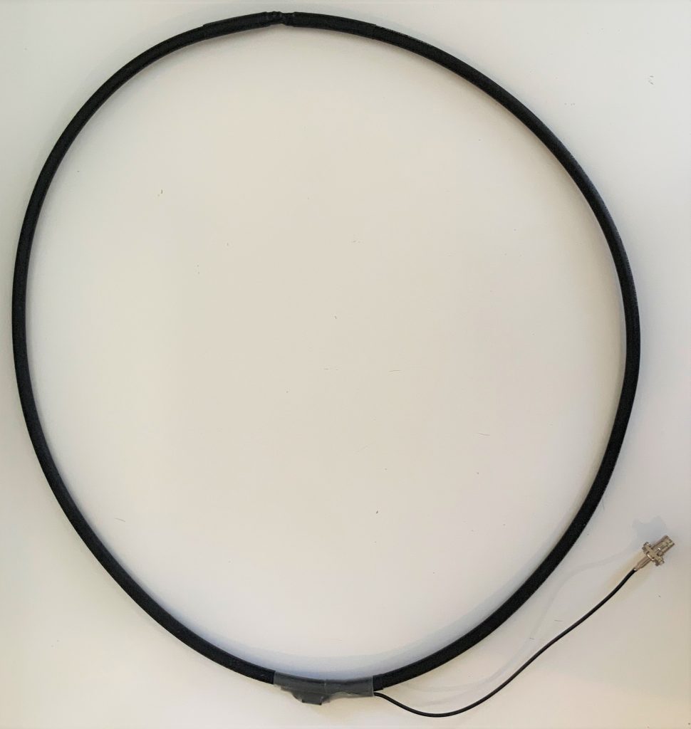
I’ve gotten quite a few emails from Post readers telling me that the only thing holding them back from building a NCPL antenna is the BN-73-302 binocular ferrite core needed for the 1:1 Balun. While so much of the world is sheltering at home due to Covid-19, it’s less convenient to purchase one just for this purpose.
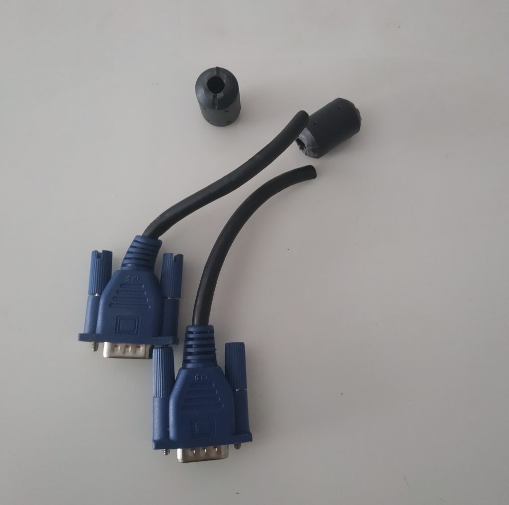
But almost everyone has an old VGA or USB cable with ferrite cores they can cannibalize for this very purpose. Oscar shared this super-simple hack on Twitter:
1. Cut the cable and remove the ferrite cores
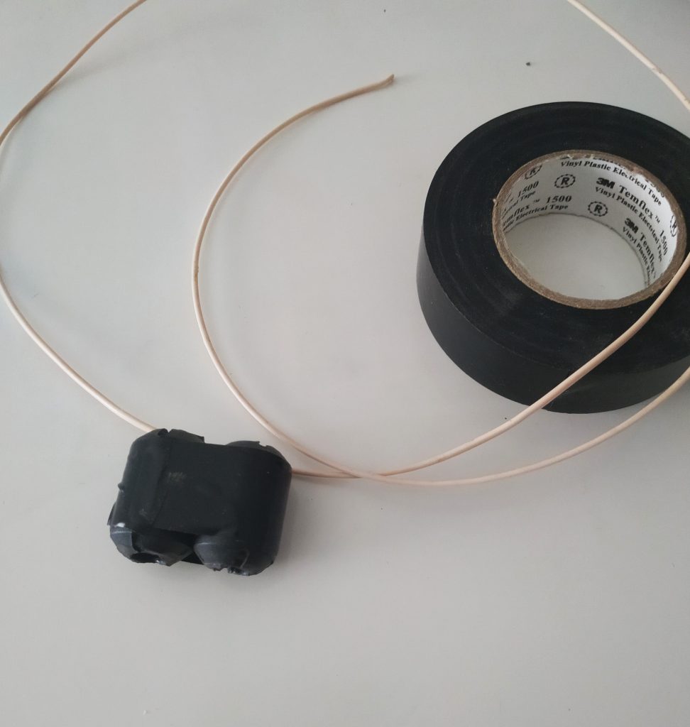
2. Tape the two cores together
3. And wind four turns on both sides
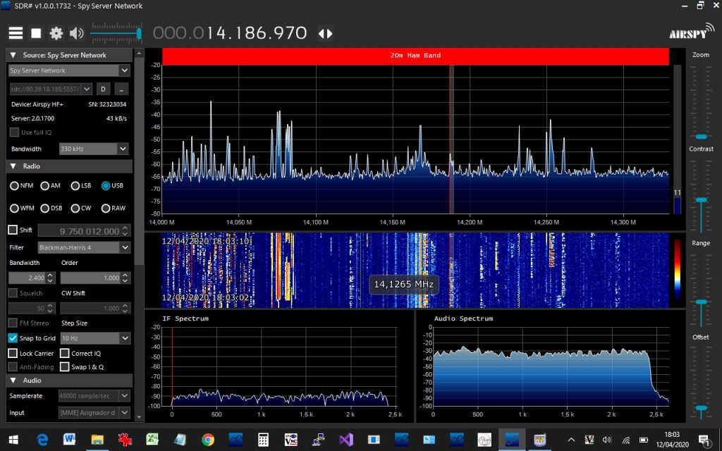
Admittedly, this 1:1 balun might not have the same properties as the BN-73-302 from our tutorial, but it seems to be working for Oscar. Check out this screenshot he shared from SDR# while hooked up to his NCPL antenna:
Readers, you can follow Oscar on Twitter by clicking here.

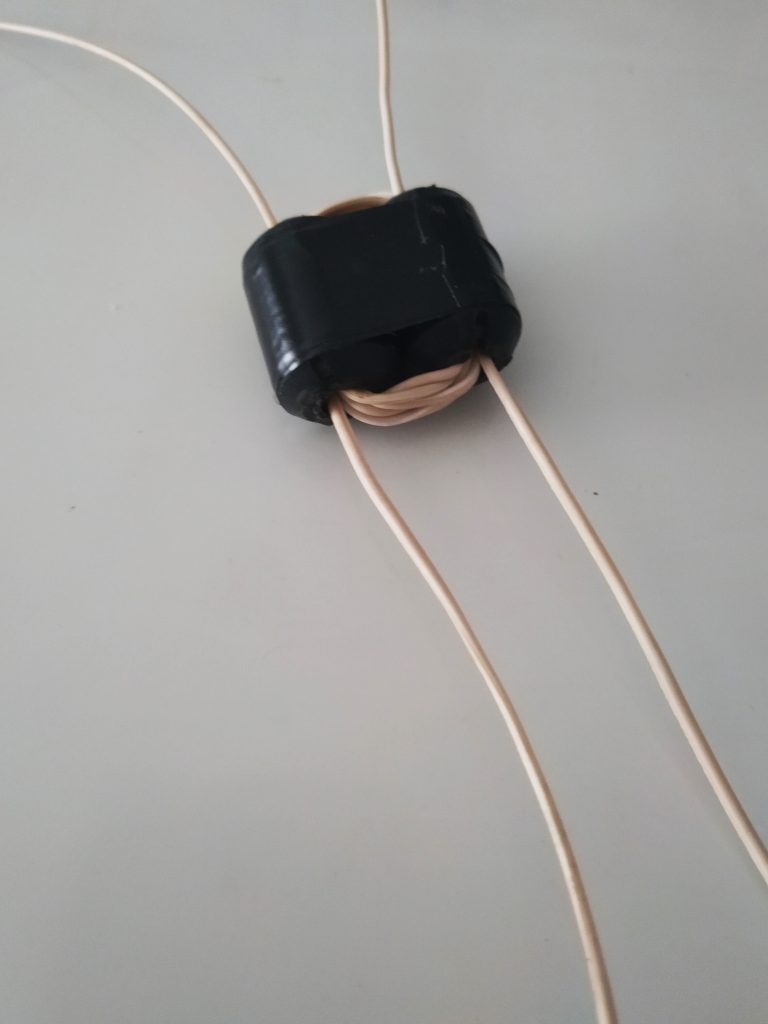
It’s incredible how well this works. I built one out of two different ferrite cores (due to breaking one in the process), and also used some heavily isolated wire and although performance could probably be improved even further, it does it’s job rather well.
I was grabbed by the YouLoop concept and recently built a couple of my own, teamed up with an Airspy HF+ Discovery.
I’ve had great success with VGA ferrites, although I removed the outer plastic covering from mine. Having the ferrites in direct contact with each other also will allow for the greatest coupling between them and will give better performance.
I also used some magnet wire I removed from a junked solenoid coil, again in an effort to achieve the greatest effect.
I’m amazed how well this works!
Hello to all,
Interesting article on home built NCPL antenna. I have the You Spy Loop that I ordered a while back thinking it would work with my Icom R75, but supposedly only works with SDR receivers. Wonder if it would work with the Icom IC 705?
Thanks,
Jerry
Attention: I just cut several VGA HS cables and I realized that for the most part it did not actually contain ferrite in the plastic protrusion above each sub-d 25 connector.
be careful when you recover so you think you are recovering the ferrites of this cable which is not good. if you can cut with a simple cutter blade in two the thing is that it is not fries but that and only a rubber outgrowth and therefore a bad VGA cable. I think a lot of Chinese copy themselves but melt what I would call bad clown while making us believe they are completely normal. many will see it as fire not realizing what we are doing there. so be careful because otherwise you risk like me using what you believe to be ferrites and that it will make you not have a good performance or functioning in the realization of the antenna.
Wait – there’s people out there who don’t have handfuls of binocular and toroid cores of various mixes lying around in their parts box?
And they say I’m the strange one… 😉
If one doesn’t have the binocular core, the transformer may be wound over a toroid and if one doesn’t have the correct wire, either, just use red/black speaker wire, wind the desired number of loops, spread them evenly around the toroid and lock them with some tape, separate the red/ black wires at both ends and connect them, notice that depending from the permeability of the ferrite you may need to wind more loops, as long as the ratio remains the same for both windings
Just to be (hopefully) more clear, in this case having a 1:1 balun the number of winding is the same for primary and secondary, so it’s just a matter of winding some more loops if the ferrite parameters aren’t the desired ones (to a certain limit btw I’m just trying to keep things simple) in other cases just use the square root 🙂 not kidding, for example willing to wind a 9:1 balun, we start by calculating the square root of 9, that is 3, that will give us the turns ratio so we may wind 6 turns + 2 turns (6/2=3) or if the ferrite hasn’t the right parameters we may increase the number of turns to e.g 12 and 4 and tge ratio will remain the same
HTH
To be even more clear, the winding around a toroid may be like this one
http://vk5ajl.com/projects/img/balcur.jpg
but in our case (1:1 transformer balun), the connection will be different from what indicated in the image, that is, the two red wires will go to the antenna and the two black ones to the feeding coax (or the reverse, the colors just indicate the two separate windings), just notice how the wire is wound so that the loops spread around the whole toroid
I have to admit to being confused by the winding of the balun through the binocular ferrite (which I do have) .. If I’m reading the original diagram correctly, and admittedly I’m useless at reading them, the two windings are completely separate? One winding connected to the loop, the other connected to the feed back to the RX, having done some reading, the only connection between the two windings is inductive coupling? Is this correct? Or have I got it wrong?
As I see it, you are right. Just the inactive coupling is doing the job.
That’s a good tip. I’d always assumed they were moulded on in a permanent kind of way.
Then again, the hoarder in me thinks; one day I’ll need a VGA cable to save the world, so why destroy a perfectly good one?
Mark
Thank you for this tip! I just found two VGA cables in the trash yesterday. There were some other cables with ferrite cores around them but i left them, not knowing they would be of use.
Omg, I feel you on that one.
Like one day there might be one last server that is the hope for restoring humanity, but you need a VGA cable and a RS-232…