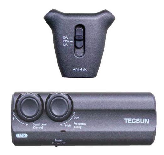
Anon-Co just announced that Tecsun has released their new portable, active loop antenna – the AN-48x (27.99 plus shipping) – and it is available for purchase. Copied below is their announcement:
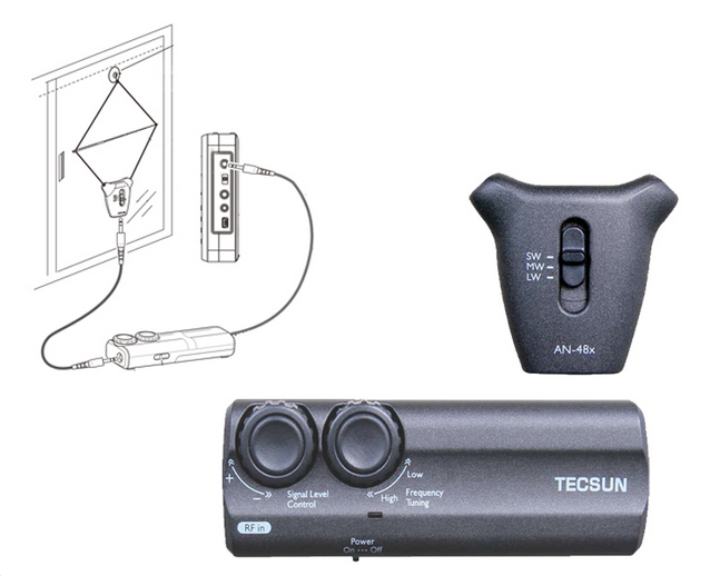
Tecsun has launched its latest antenna which is now available at Anon-Co! This active loop antenna has a portable design and aims to enhance AM (LW, MW, SW) frequencies. The antenna comes with three types of connector cable and a ferrite coupler for connecting to different types of radios.
Personally, I like my TG34 (DE31MS equivalent). Though I have *no* experience with this model – as it is new – this is the type of antenna users either love or hate. My TG34 and the equivalents will amplify everything, including noise, but it has helped me make inaudible or barely audible signals audible. It’s inexpensive, portable, easy to deploy and store (great for travel) – but it’s really geared towards the SWL hobbyist who can’t invest in, or erect, something bigger and/or more expensive.
The biggest advantage that I can see with this new model: the antenna has three types of connections including BNC & RCA sockets.
Click here for more information: Tecsun AN-48x
Guest post by Troy Riedel