 Many thanks to SWLing Post contributor, Frank (ON6UU), who shares the following guest post which expands upon his previous DB4020 article:
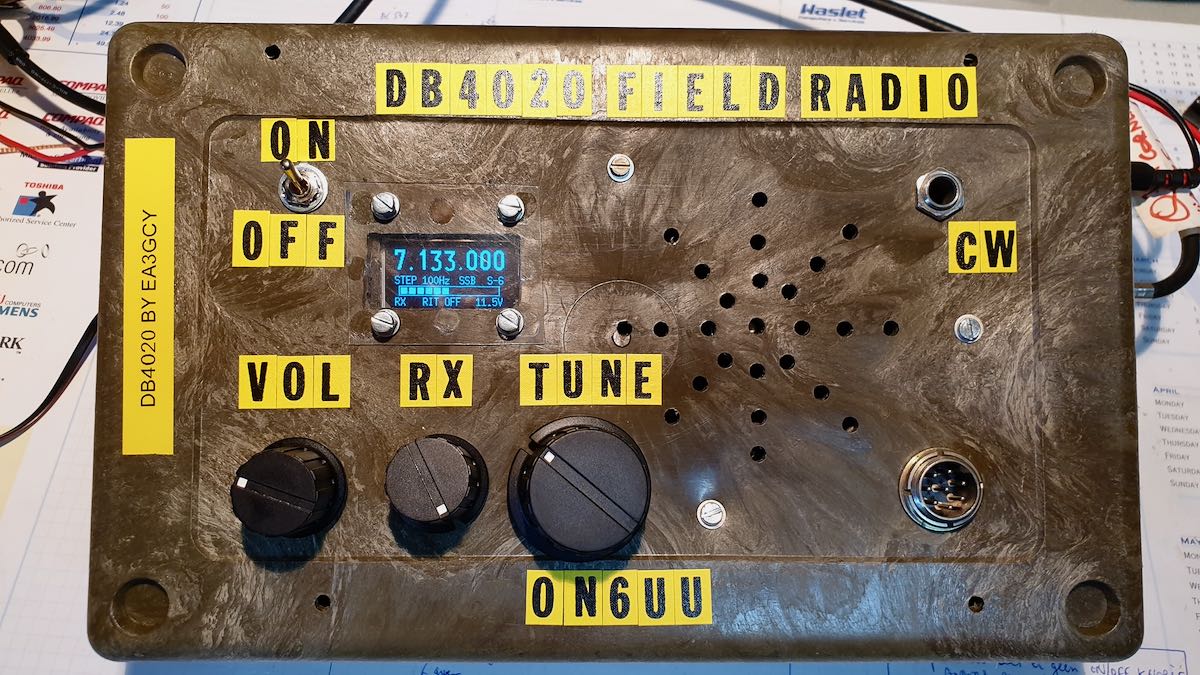
The EA3GCY DB4020 transceiver now has CW mode
by Frank Lagaet (ON6UU)
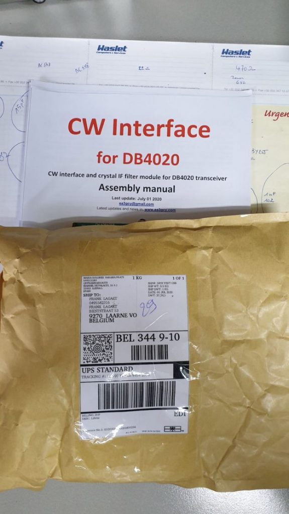
After telling you all about the DB4020 SSB build I’m here with the CW part of the kit, let’s say this is part 2. At a certain moment Javier let me know the CW interface kit was ready for shipment and some week later it was delivered to my QTH.
Again, a well packed kit arrived in a brown envelope, components and boards well packed in bubblewrap. I found even a board I did not expect which can hold a push button, a switch and the connector for your morse key. Javier thinks of everything it seems!
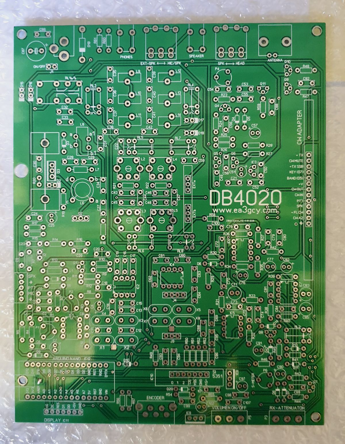
Unpacking the bubblewrap gave me this result, all components in 2 bags. In the bigger bag another 2 bags with 2 printboards, one for the CW interface, one for the CW filter. Great !! Checking the material bill resulted in all components there, another thumbs up.

I started, of course, immediately building it because I wanted CW in the transceiver as soon as possible. I don’t do much in SSB mode anymore and I already started missing CW on the DB4020, so I started my KX3 to listen to while I was populating the boards. I never thought CW was going to have this impact on me! …. ..
I started building the CW interface, again starting with all small items. I soon saw that the 2 relays which need to be soldered in were ideal to protect all components when the board is upside down, so I soldered them in very quickly. I then soldered in all other components ending with the elco’s.
Next phase was the CW filter. This board is small and came together in a blink of an eye, no problems there, the long legs of the 3 and 4 pin headers went in last.
The following day, I made all wire connections and soldered a 13pin connector, leaving one pin out since I want to have the option to choose the width of the CW signal I’m listening to. By cutting the FL CW + pin and adding an additional switch, I have now 500Hz or 2400Hz. Great option, for very little effort and simple. Another thumbs up here.
Now it was simply a matter of inserting the sub boards in the main board and all should be working. And it did! Hurray! The 500Hz filter works perfectly, filtering away all above or below stations nearby my operating frequency.
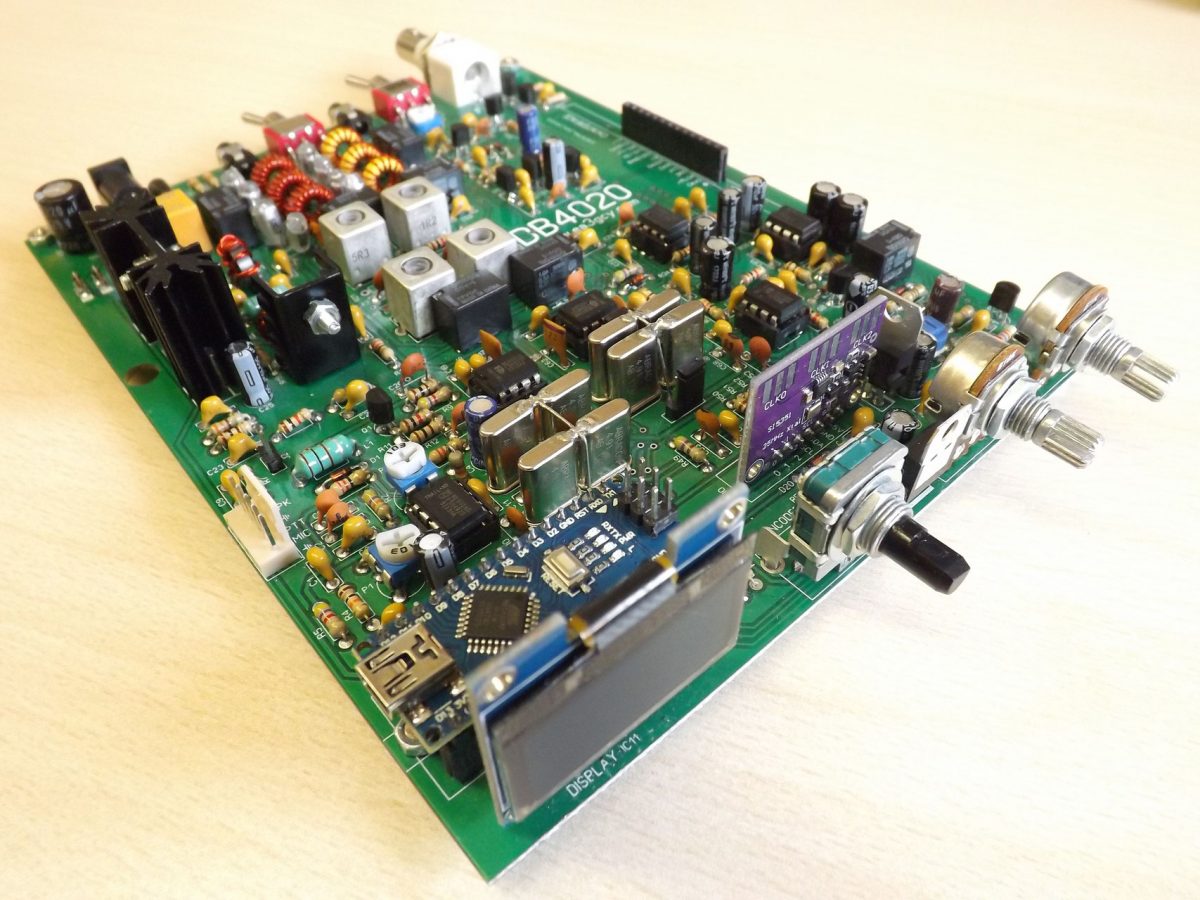
This is the result of the soldering work, 2 small boards which need to be inserted in the main board:
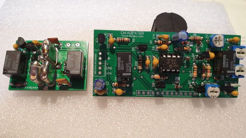
The CW interface still needs the 13pin header of which I cut one pin and mounted a switch to have the 2400Hz width.
The IC you see in the middle of the CW interface is the KB2 keyer which gives you several functions like 4 memories and beacon mode. The 4 potmeters are used to set the level on 40 and 20 meters, to set the delay between TX and RX switchover and to set side tone monitor level. The keyer also provides functions as keyer mode A or B, straight key function and can be set for speeds between 1 and 50WPM. WPM speed can be set in 2 different ways. Handy!
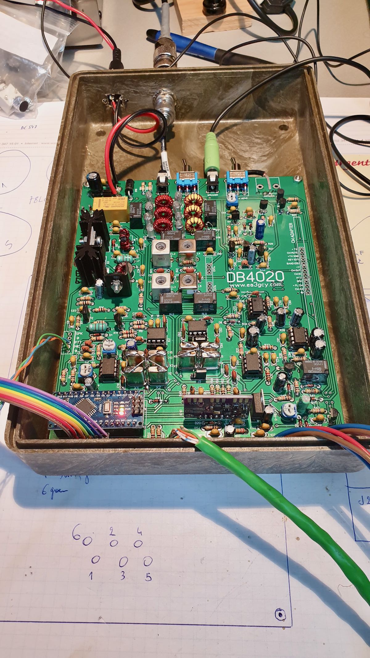
Here a picture of the CW filter inserted on the main DB4020 board.
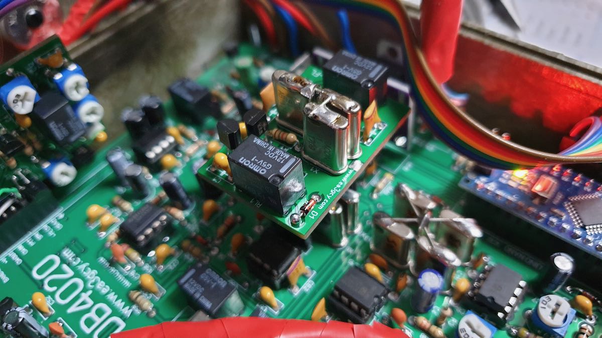
The CW interface is inserted at the side of the main board, notice the 2 wires which go to the switch to allow switch-over between 500 and 2400Hz.
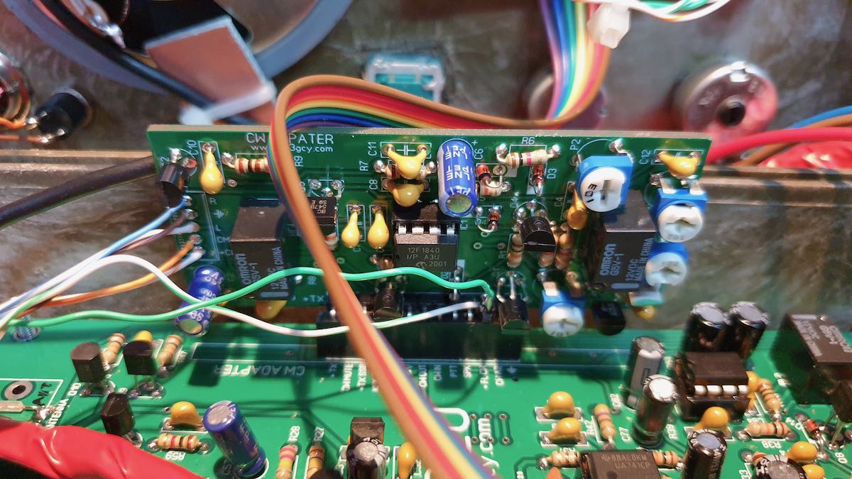
(Wiring still needs to be cleaned up in this picture.)
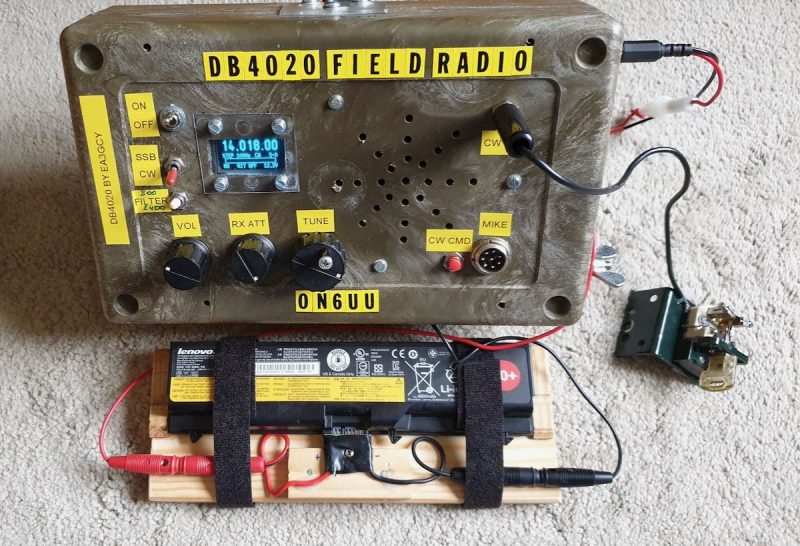
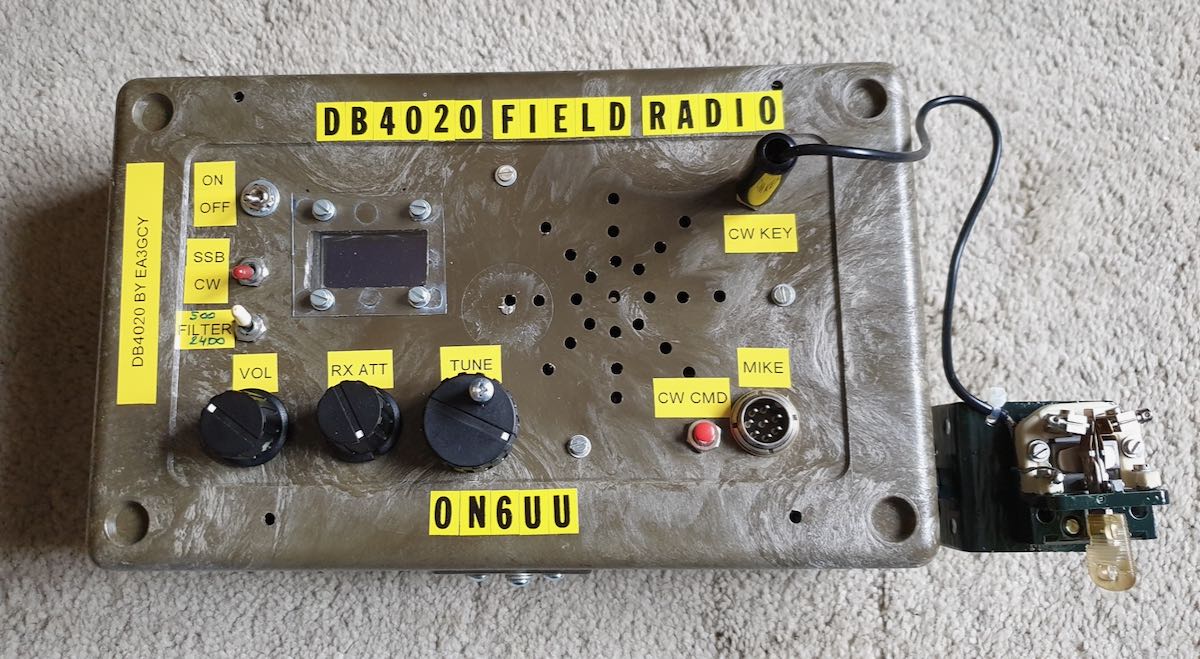
Finally, the result: a good working multimode QRP transceiver with 2 bands. It should be possible to make close to medium range with it as well as DX, even with QRP power.
And while I was building I also made a new key for this radio, it is made out of a relay and cost nearly nothing, looks good doesn’t it ? hihi.
Homebrew key
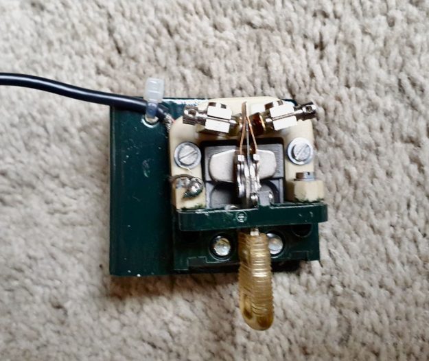
The key, when in practiced hands (fingers hi), can do 50 WPM without a problem. My friend HA3HK does without blinking an eye at 40WPM with this kind of key and tells me that he can go faster if needed. Me? I’m going it a bit slower.
Battery pack
As this radio is only using little power (0.4A in RX, 1 to 2A in TX depending the power you set it) I thought, let’s make a battery pack for the radio.
The first plan was installing it in the box. I did not do that because the batterypack is also powerful enough to feed my KX2 and other QRP transceivers. Since I can use it with all of them, a loose battery works out better for me.
I started with an old laptop which had a broken screen and some other malfunctions, but still had a good battery, although I needed the battery connector of course. A piece of wood to mount the connector on was my next goal. And since I still have another laptop using the same batteries, I can charge the battery without problems. Simple, but good and it weighs much less than a gel cell battery.
The battery provides me with 12.5V and some 5Ah. Enough to last for hours on RX and for sure good enough to activate 2 SOTA sites in one day. It doesn’t look great but works great– that is what matters and to test it was more then good. Next will be getting the battery pack in a nice box. Better to re-use stuff than throwing it away I’m thinking.
I need to do something about the cover of the OLED display, there is still some work there to make it look nicer.
Some video can be seen on YouTube :
Finallym I’d like to thank you all for reading my articles about the DB4020. I had big fun soldering, tinkering with the box, making the key, and batteryholder/batterypack. My Hungarian friend HA3HK told me it looks a bit like a spy radio. …. ..
I also include one more time the link where you’ll find this kit :
https://www.qrphamradiokits.com/
73 TU ee
Frank
ON6UU
Thank you so much, Frank. No doubt, you had a lot of fun putting this excellent little kit together.
Implementing a filter switch was a fantastic idea and, obviously, not terribly difficult to do.
Based on the videos, the DB4020 has a low noise floor and very good receiver characteristics. I’m impressed that the CW portion of the radios has so many features as well, such as a memory keyer and beacon mode.
I also love how you reused that 5Ah laptop battery! I think that could almost give you a full day of SOTA activations at those consumption levels!
Thanks again for sharing this with us, Frank! We look forward to your future articles!