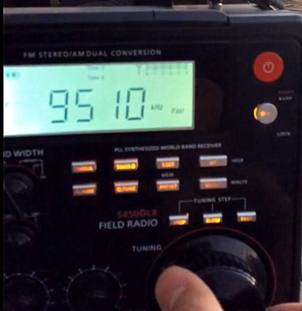
Yesterday, Tony (K3DY), shared a video (via Twitter) demonstrating his new home brew loop antenna and amplifier.
This is actually a great demonstration of how even a relatively simple, inexpensive loop antenna can improve reception in locations with heavy radio interference. Tony includes the following notes with his video:
“Testing a new receiving loop antenna that I built today. It uses a pre amplifier based on deferential setup of two 2N5109 transistors. Loop is made out of coaxial cable, only the shield is connected to the circuit.
Quick demo on 31 meters, lots of stations at sunset time. No time for further testing but I observed a pronounced directivity below 7 MHz. 75 meters is so quiet that it makes me forget I live in a townhouse. As a comparison, my noise level on 75 meters is at S8 on an end fed [antenna].
https://www.youtube.com/watch?v=bq_gKNQSVeA
I will use this loop primarily for SWLing purposes but I may use it as a separate receiving antenna with my amateur radio equipment.
A lot of fun, loops are fascinating and efficient!
Indeed, Tony! And perhaps the icing on the cake is that loop antennas are so portable, low-profile and easy to deploy. They’re ideal for those living in restricted areas and with picky home owners’ associations.
Inspired by my buddy Vlado (N3CZ), I’ve actually been collecting the pieces to build my own mag loop antenna this winter. I doubt the parts for my loop will exceed ten dollars as I plan to use the shield of some heavy coax for the primary loop and a little PVC for support (much like Tony’s loop).
Tony’s video is inspiring me to go a step further and also build a simple amplifier. Any suggestions or schematics for doing so are most welcome!


Here is my experimental design from the year 2003:
http://www.iki.fi/uusitalo/doc/Regen-SW-Loop.html
It provided considerable directivity, effective preselection and high amplification when using the regenerative amplifier circuit. However, the regenerative circuit had some major drawbacks: frequency instability and too abrupt start of self induced oscillation when adjusting regeneration by using the variable resistor RV.
Currently, I think I would make at least the following changes to the circuit:
1. I would connect the cold end of the variable capacitor CV to ground to reduce hand effect on frequency.
2. I would connect the cold end of the coil L1 to ground via a new capacitor C1 instead of connecting L1 directly to CV. C1 should be sufficiently large to avoid it affecting the tuning frequency.
3. I would move the resistor R1 connection from transistor base, which loads the tuning circuit, to the cold end of L1 to avoid loading.
4. I would use a higher gain transistor to further reduce tuning circuit loading and recalculate R1 accordingly.
Then this all should be tested in practice to know, whether these improvements are gained in reality and not only in my imagination.
One might alternatively replace the regenerative circuit with a different one, for example this one: http://www.ke3ij.com/am-univ.htm
Thanks for sharing these notes! I’ll look into this!
Cheers,
Thomas
Thomas, by amplifier, do you mean a LNA ?
Hello Medhi,
To be precise, it is an impedance-transforming amplifier. The size of the passive element (the coax loop) on my version is 10 feet long which gives about 3 feet in diameter.
The impedance increases dramatically at 14 MHz with these dimensions so it would be preferable to make a half sized version if one wants to listen to the higher bands.
Since I’m connecting the loop to my “Home Depot” junction box with SO239 mount, I will be able to experiment with different lengths. Low band DXing season is approaching so I will probably be fine with the current sized loop.
73
Tony, K3DY
Thanks Tony.
Can you guide me on improving my reception with my radio? (I’m a beginner)
I have an inverted-vee antenna which I use with my SDR, but that would overload my portable radio’s input.
So, I need something like your setup.
I do have a LNA4HF and I live in a crowded noisy environment.
I have tested active loop antennas, but they amplify noise too, so they’re not useful for me.
I’m thinking of building a magnetic loop. Can I use my LNA4HF?
Thanks
Mehdi
Hello Mehdi,
first you should determine where the most noise comes from. The power supply is a prime candidate. Then you need to determine where your antenna current may run along. So do not try to “end feed” your antenna as this can hardly ever done. A balun is always a good idea.
If your normal antenna overloads your radio try some selection in front of your receiver. If nothing else helps insert an attenuator.
Tony made the same discovery as London Shortwave some time ago: “End-fed” antennas are not end-fed. Those antennas are only a part of the real antenna system as antenna is where unsymmetric currents flow.
A loop antenna is especially benificial in densely populated areas and for indoor reception as they use the magnetic component of the electromagnetic field. Most electric noise is electrostatic by nature.
BTW: Most antennas that are much shorter than the wavelength are more or less capacitors against their surroundings and therefore electrostatic by nature.