
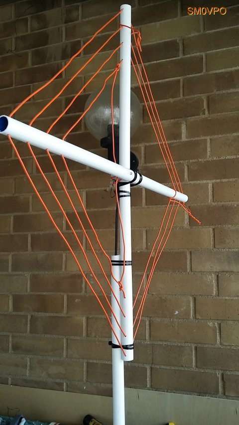
The completed antenna.
Many thanks to SWLing Post contributor,Harry Lythall (SM0VPO), who shares the following update to his excellent homebrew 20 meter magnetic loop antenna post:
3D Printed 10KV Tuning Capacitor
by Harry Lythall (SM0VPO)
Introduction
You may have seen my 20m (14MHz) loop, or frame, antenna, and the ease of construction with just a bit of wire and a bit of plastic tube. The tuning arrangement is a little primitive, using just a “gimmick capacitor”, comprising two bits of wire twisted together.

The original “Gimmick” capacitor that burns.
This arrangement works very well for QRP, where the average RF power is about 5 Watts or less. If you exceed this power level, then the twisted-wire capacitor tends to warm up and the tuning drifts a little. But if you use more than about 10 Watts of continuous RF power, then things start to burn. Cheap insulated wire also smokes. This is because the impedance at the ends of the coil is so high that you can get many 100s of volts and the insulation, normally intended for house wiring, breaks down.
In this page I will show you how to build a super-cheap tuning capacitor that will tolerate up to 10,000 Volts of RF and allow you to use up to about 100 Watts of RF into my 14MHz (20m) antenna. The capacitor is also tunable so that you can adjust it by hand (when the RF is removed, of course :-). The tuning range is about 8pf to well over 30pf when really compressed. The normal range for the antenna is about 12pf to 15pf.
Construction
My prototype does not look very pretty, and it is not supported on anything other than the connection wires from the antenna. Very few components are used:
- two plastic foam pan scrubbers or one thick plastic bath sponge
- two pieces of metal 4cm x 6cm. Copper-clad board works fine
- one plastic nut and bolt – see text
- one heavy-duty 3-pole block connector with centre-pole removed
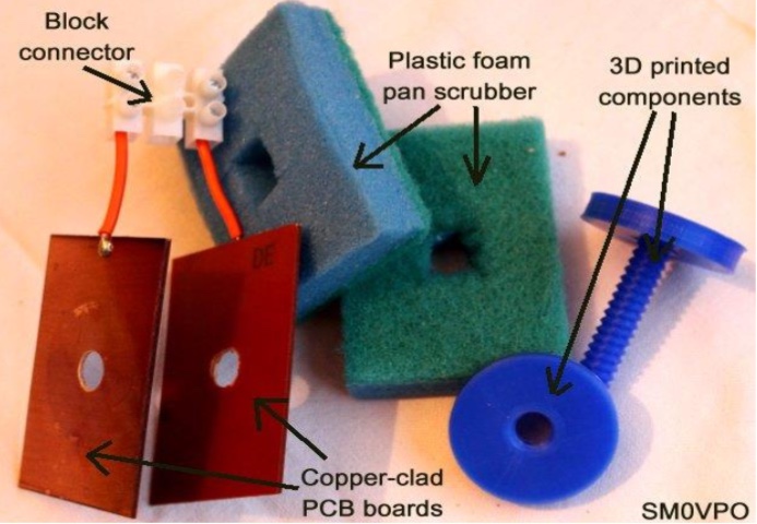
Components for the 10KV tuning capacitor
The plastic nut and bolt need to be about 6cm long and totally non-conductive. If you want to make my bolt, then do NOT use black plastic because some black plastics use carbon as a colouring agent. You can use a nylon bolt, as used to secure IKEA toilet seats, but you will also need a washer to spread the stress, otherwise the copper-clad board tends to bend under the stress with time. I chose copper-clad board because it is easy to solder – no need for drilling or connection bolts. I made my plastic compression tuning bolt using my 3D printer. I have included the project files for you to download.
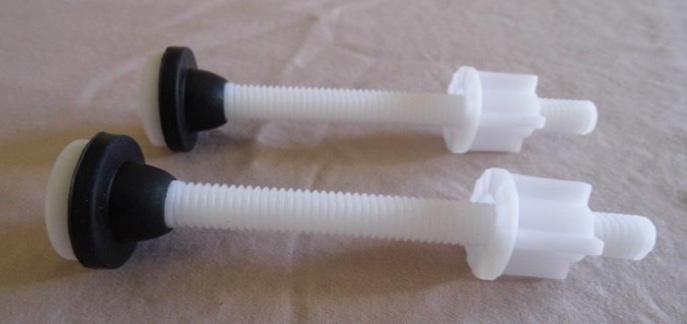
Ikea toilet-seat bolt
Note that the connector for the wires needs to be well spaced between the metal inserts, in order to tolerate up to 10KV, so I used a 3-pole connector and took out the centre pole. At 100-Watts continuous there is a very slight warming after a few minutes, but no sign of smoke, sparks or corona. 🙂

The connector with the centre-pole removed.
I tried a few different types of plastic dielectric and all worked well, providing they are 100% dry. The best ones those I stole from the kitchen cupboard (when Maj-Lis was not watching). I think it costs about $1.50 for a packet of 10 pieces. Perhaps I should have used a nicer colour? A pretty pink? Heart-shaped? No! maybe that would be going a bit too to far ;-). Here is my finished capacitor using my 3D printed tuning screw.
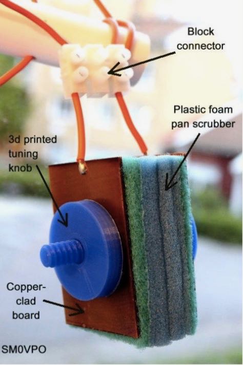
The assembled 10KV capacitor.
3D Files
Once more, this project is ridiculously easy to make with a 3D printer. The hardest part was to get the pitch of the threads right, then clone/connect the pieces to get a longer thread. They were printed with the bolt vertical, so the slope under each thread is a steeper angle than the upper slope. This makes the printout a lot easier to print. If the angle is too steep, then it may extrude PLA into mid-air. My nut and bolt heads are about 3cm Diameter, and the 10mm thread for the nut was cut using boolean subtraction. I then enlarged the nut by about 3% so it still fits but there is a little slack so that it does not bind. I may have overdone it a little, but not much.
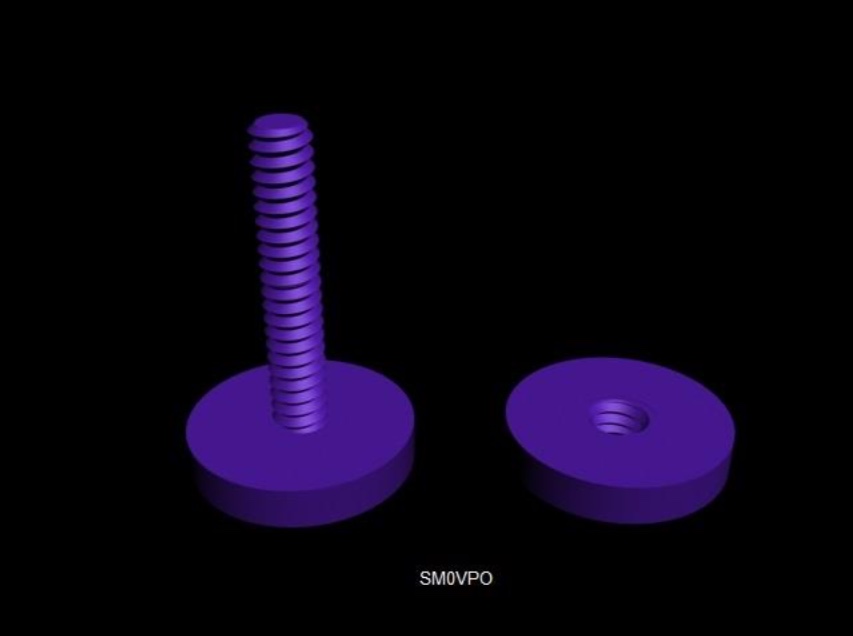
Project rendered in 3D Studio Max
Here are the files:
3D studio MAX file – 3d-cap-01.max
ASCII STL file – 3d-cap-01.stl
ASCII OBJ file – 3d-cap-01.obj
the GCODE file for my Wanhao (Prusa) Duplicator i3 – 3d-cap-01.gcode
Just right-click on the file and select “save as”. Some web browsers try to open ASCII files instead of saving them. I usually export STL files, but on this occasion, I tried comparing OBJ files since CURA slicer will accept both. Although I use a WANHAO replica of the PRUSA Duplicator i3 printer, the GCODE files are rather generic and will probably work on most printers.
My printer settings in this GCODE are:
- Nozzle temperature = 200°C
- Bed temperature = 60°C
- Support structure = brim
- Layer height = 0.1mm
- Print speed = 60mm/s
- Fill density = 40%
- Shell thickness = 1.2mm
The printer temperature is 200°C, which is 5°C hotter than recommended for PLA filament. I find that I get a better print at 200°C as it sticks to the bed a lot easier. When printing this screw thread, it may be advisable to start at 200°C and then turn down the nozzle temperature to 195°C after a few layers have been printed.
I hope that you find this project interesting. It is a bit small, but it gets me active on 14MHz from my car with this portable antenna. I have a new car and I don’t want to start throwing long aluminium tubes in it that scratch the interior to bits.
Don’t forget to visit my messageboard if you have any questions about this or any other project. I always look forward to receiving feedback, positive or negative ?
Very best regards from Harry Lythall
SM0VPO (QRA = JO89WO), Märsta, Sweden.
EA/SM0VPO (QRA = IM86BS), Nerja, Spain.
Thank you so much for sharing this, Harry! I love both the frugality and ingenuity in this unique capacitor design!
Post Readers: be sure to check out Harry’s website which is loaded with radio projects of all stripes. You’ll easily spend a few hours digging through his tutorials and downloads. Harry also maintains an alternate mirror server located here.
Shades of the old mica tuning cap. It would be interesting to note the dielectric constant of the sponges. The dirty little secret of mica is the dielectric constant rises in compression so capacitance increasing without decreasing distance.(solids don’t compress). The sponge density (assuming the sponge material has a higher dielectric constant than air) would work the same way. The only concern is if the sponge gets wet ( its design purpose) leakage current rises and “D” (dissipation) rises making a lossy cap. Keep it dry out of the rain.
Did not know this was possible! I will have to try it.
Thanks for posting!