
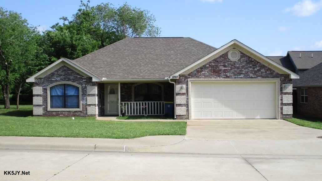
Can you spot the antenna in this photo?
Many thanks to Matt Roberts (KK5JY) who has kindly given me permission to re-post the following article he recently published on his website KK5JY.net. Many thanks to SWLing Post contributor, Grayhat, for the tip!
Note: The Porch Loop project below is a re-configured Small Receiving Loop (SRL) antenna. For SRL construction details, check out Matt’s primer.
The Porch Loop
by Matt Roberts (KK5JY)
The small receiving loop, or SRL, is a versatile, effective, and very space-efficient receive-optimized antenna for the HF bands. They are easy to build, and can be made very inexpensively. Most typical designs use symmetric shapes, like circles, diamonds, octagons, etc., and are mounted on some kind of mast. This makes it easy(-ier) to install the antenna clear of nearby metal and electronics. It also makes the antenna rotatable, so that the nulls can be pointed at RFI sources.
These aren’t the only options for the SRL, however. These little loops can be made to fit in just about any available space. In fact:
- They are effective at any reasonable installation height, including very close to the ground. The installation height doesn’t change the pattern shape, only the pattern strength.
- They can be made nearly any shape. The shape does not have to be symmetric about any axis or combination of axes.
- They can be fed at just about any point on the loop. A typical feed location is bottom-center, but off-center feeding has negligible effect on the pattern shape.
- The wire can be bent out-of-plane; in other words, the loop doesn’t have to be “flat.”
There are a couple of requirements for obtaining predictable performance, however. First, the antenna does need to be an electrical loop. That is, it is a single wire connected between the conductors of the feedline, forming a complete circuit. Also, the circumference of the loop wire should be electrically small (i.e., significantly less than ? / 4) on the bands where it is to be used.
Figure 1. The antenna location (click to enlarge)
As a personal challenge, I recently installed such a loop on my front porch. Everything about this installation defies conventional wisdom — it was installed very close to the ground, it was an irregular shape, it was fed off-center, and the wire was wound in and around an irregular support structure, rather having all the wire in a single plane.
And the resulting antenna still performed very well.
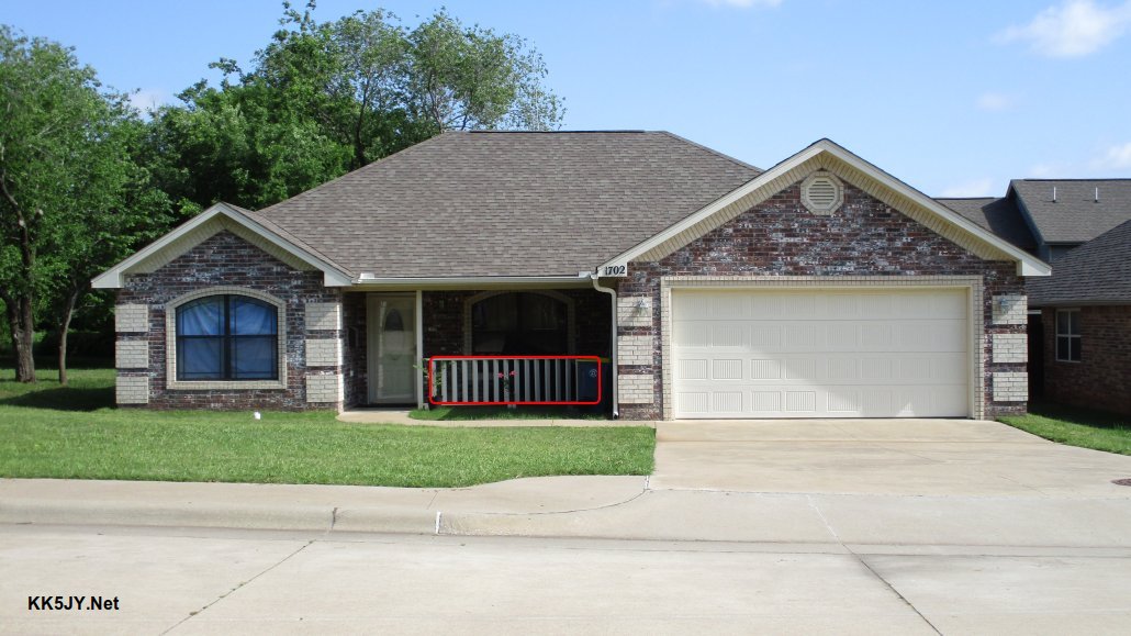
Figure 2: Antenna Location Outlined in Red (click to enlarge)
The loop is essentially the same device as the one in the original SRL article. See that article for more construction details. This version is simply stretched and twisted to make it fit the space and supports available. The wire was woven around the boards in the porch’s deck rail, and fed off to one side, so that the transformer housing could be “hidden” behind the trash cans.
Figure 3: Feedpoint Transformer (click to enlarge)
The wire was insulated with an off-white THHN, which made it blend in with the color of the trim of the house.
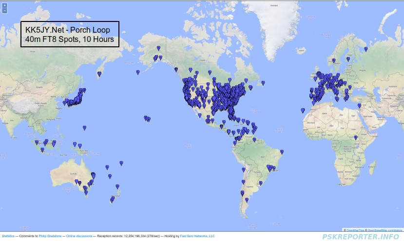
Figure 4: 40m Reception 10h Overnight (click to enlarge)
Even with its suboptimal installation details, the overnight 40m DX spots were numerous and well-distributed, as seen in Figure 4. There were DX spots at nearly 10,000 miles, there were NVIS spots, and there were countless at all distances in between. So the antenna was just as effective as its more ideally shaped brethren, despite it’s unconventional installation details.
Other ideas for possible locations of such a device could include:
- In an attic. The antenna could be nailed to a vertical panel, or strung like a spider’s web inside the frame of a truss or other open area.
- Under a tree. Taking another idea from the spiders, the antenna could be hung and pulled into shape using light guys or tree branches.
- On a wooden fence. If you have a wooden fence, the antenna could be installed against the fence panels. This option could allow a wide range of circumference lengths.
- Attached to an interior wall of an apartment. The shape could be chosen to keep the loop clear of in-wall wiring, to help preserve its performance.
The original mast-mounted SRL antennas still have some advantages. Perhaps the biggest advantage is that they can be easily rotated to null out a nearby strong noise source. That said, if you are looking for an antenna with better receive performance than a large resonant vertical, the SRL can be stretched and squeezed into service just about anywhere.
Many thanks for sharing this project, Matt! So many of our readers live in situations where they are forced to use stealthy and compromised antennas. What I love about your porch loop is that even though it breaks several loop antennas “rules,” it’s still amazingly effective.
I encourage SWLing Post readers to check out Matt’s website as he has written articles covering a number of interesting radio and antenna projects.
Can’t reply for Matt, but my guess is that using the 9:1 he got wider bandwidth, at least it seems so by reading what he wrote about the “SRL” (small receiving loop) from which this latest loop was derived, or probably he used the 9:1 since he had it at hand
Good work. 🙂
BTW, quick thought on the overall design. I get the ground isolation aspect for the transformer, but otherwise, is there a particular reason for the 9:1 impedance transformation?
Fractional sub-wavelength loops tend to be low impedance, especially as frequency and size decreases. While most any decent modern receiver probably has more than enough gain to deal with even rather low impedance antennas, it seems somewhat counter-intuitive to drop the ohms of an already low impedance antenna even further; depending upon the desired frequency range of course.
I would think an 1:1 isolation transformer might be preferable for general HF reception, or if targeting say 160m or lower with a comparatively small loop, perhaps flip the existing 9:1 design to an 1:9 transformer. YMMV.
As to the impedance of loops I think it’s more frequency dependent is it not? As for the ratio, I think you’re right on the 1:! isolation transformer idea. I’ve tried higher ratio transformers with small loops and not much changed in their characteristics beyond the highest frequency of reception for me. Type 73 material in my experience tends to favor the low end of the HF bands as well so maybe try a type 43 core? Probably BN-43-302 since it won’t have as much inductance so you can get away with more windings for better coupling.
Correct about frequency. A 2:1 or even 4:1 would be more ideal for loops larger than one wavelength.
As frequency drops, through, loops far smaller than one wavelength tend to go very low in impedance. That is one the reasons why vacuum variables are often used for very small transmitting loops.
I am like you. I think an 1:4 or 1:9 might be more appropriate if targeting very low frequencies as loop size becomes very small compared to wavelength. Maybe even 1:49 or higher if going to down to mediumwave or longwave with a small loop.
I also agree about ferrite mix. Some ferrites behave quite different outside their intended operating frequencies.
Then again a transformer depending upon design also can add shunt resistance at low operating frequencies, so that might be why a basic 9:1 can suffice for these types of low impedance receiving antennas. There also is the idea of the associated increased losses along the mismatched feedline allowing for wider frequency response at the terminating ~50-ohm receiver.
Take the Comet CHA-250B wideband vertical for example. It is “usable” for transmitting to below 80m despite being just 23’5″ long. Apparently it uses shunt resistance through a lossy 6:1 unun paired with a resistive load across the secondary. G8JNJ has a similar antenna wideband HF vertical using a 5:1 transformer constructed of a double stack of ferrites similar to type 33. Like the CHA-250B design idea, his antenna works via “optimized” losses to improve the wideband impedance matching of a 6.5m vertical.